AnNajah National University Faculty of Engineering Civil Engineering


 Ø Slab weight = 9665. 5 KN Ø Columns")

: The max. load that we found in this")


, I=")


")
")
")


 =")
: Loads: Materials: Wall load=18")

- Slides: 46
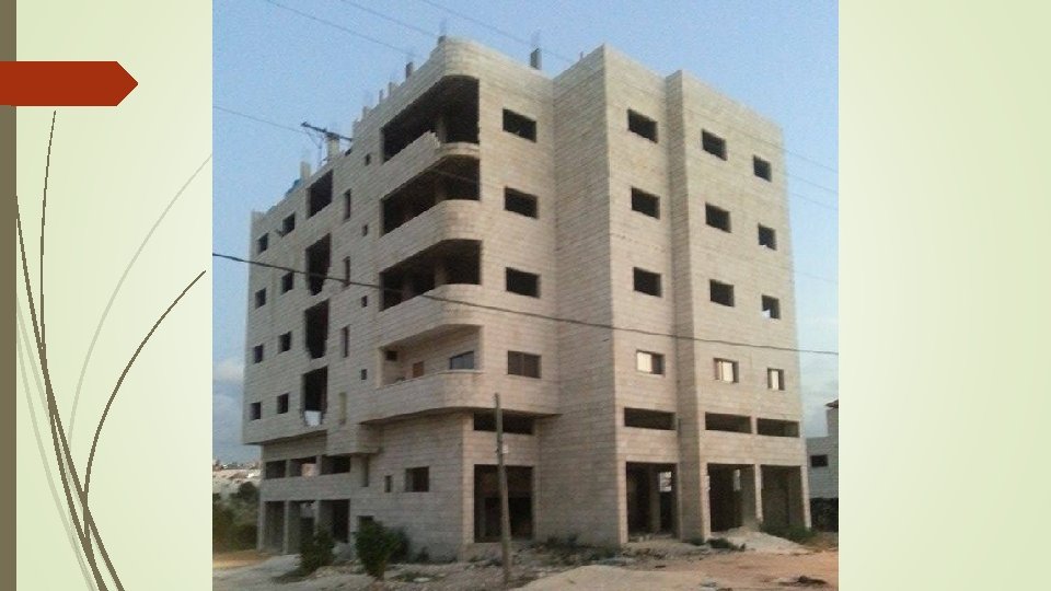
An-Najah National University Faculty of Engineering Civil Engineering Department Graduation Project II Structural Design of AL-Rehana Building Prepared By: Basel Hassan Majd Barham Mo’tasem Saidi Saleh Se’bas Supervisor : Dr. Munther Diab
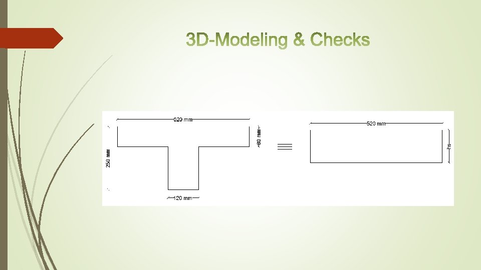
Presentation Outline q Introduction. q Preliminary Design. q 3 D- Modeling & Checks. Ø Slabs. q Design of columns (static). q Dynamic analysis : Ø Dynamic analysis for seismic loading Ø Analysis and design of slabs (dynamic) Ø Analysis and design of beams (dynamic) Ø Analysis and design of columns (dynamic) Ø Design of footing q Special structural elements Ø Stairs Ø Tie beams
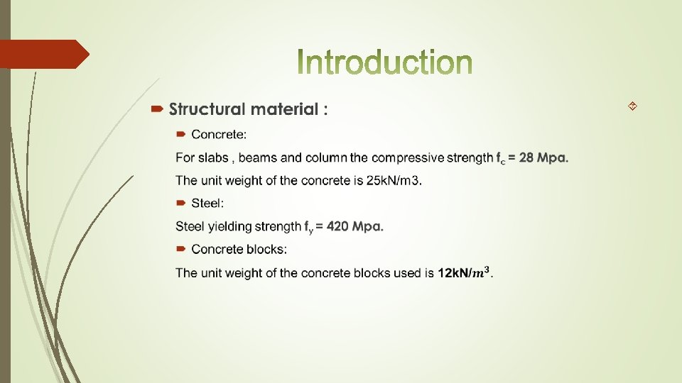
Non. Structural material :
Loads Dead loads: Static & constant loads, including the weight of structural elements (own weight) super imposed dead loads = 3. 5 KN/m 2 Live loads: Non permanent loads on the structure like weight of people, furniture, water tank & the building content. = 3. 5 KN/m 2 Perimeter Wall: The weight of the perimeter wall 18 k. N/m.
Codes The most commonly used code in the modern world that used mainly in Palestine is ACI 318 -08 which is used in this project. Load combination: U 1 = 1. 4(D. L) U 2 = 1. 2(D. L )+ 1. 6(L. L) Sap 2000 programm , will be used in analysis of the structure.
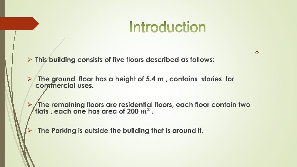
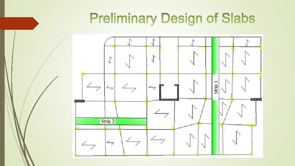
In this project two slab systems are used which are: * One way solid slab. * One way ribbed slab plan:
strip 1 Ribbed Slab Solid Slab
strip 1 Solid Slab Ribbed Slab
Ribbed Slab Solid Slab
Solid Slab Ribbed Slab
Modifier values for different structural elements. Structural element modifier Column &shear walls 0. 70 Slabs 0. 25 Beams 0. 35
Modifier calculations for ribbed slab
Compatibility: The structure works as one unit is verified.
Solid Slab Equilibrium: (5% acceptable) Ø Slab weight = 9665. 5 KN Ø Columns weight = 2145 KN Ø Beams weight = 4462. 72 KN Ø Shear wall weight = 911. 63 KN Ø External Walls = 7785 KN v Total dead load(by hand) = 24969. 9 KN Total dead load (from SAP) =25107. 737 KN Difference %=[(25107. 737 -24969. 9)/ 25107. 737] *100%=0. 55% <5% so it is Ok
We will take the columns that have the same dimension and design them together, so there are two groups of columns which there are 20*55 & 30*55 Pu=0. 8 Ф[0. 85 f'c(Ag-As)+Fy*As]= Ф=0. 65 for tied columns. f'c=28 Mpa As=ρ*Ag Assume ρ=0. 01 (economical percentage of steel) Fy=420 Mpa
Sample Calculation The group of (20*55): The max. load that we found in this group is 1254. 30 KN 1254. 30*10^3 = 0. 8*0. 65 [0. 85*28 ((550*200)-As)+ 420*As] As = 521. 64 mm 2 use 6 Ф 12 For stirrups: use Ф 8 mm stirrup: And a spacing S between the stirrups is the minimum of: 16 *db =224 mm 48 *ds =384 mm use Ф 8 mm /200 mm.
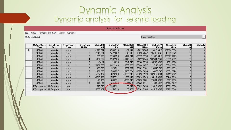
1. Introduction The main methods of dynamic analysis are the response spectrum analysis and the time- history analysis. UBC 97 code and response spectrum analysis are used in this project for seismic loads. Manual computations from UBC 97 code are use with appropriate factors Ca, Cv, R, I, and Z.
2. Seismic Loads Main factors according to UBC 97 code: Z= seismic zone factor, for Tulkarem city (Zone 2 A); Z= 0. 15
2. Seismic Loads Ø I= importance factor. From Table 16 K (UBC 97), I= 1 Ø R= numerical coefficient representative of the inherent over strength and global ductility capacity of lateral- force- resisting systems. R = 6. 5 (Dual systems concrete shear walls with IMRF) according to Table 16 N in the UBC 97 Ø Soil is rock so soil profile type SD from Table 16 -J (UBC 97) Ø Ca=acceleration seismic coefficient, from Table 16 -Q (UBC 97) Ca=0. 22 Ø Cv= velocity seismic coefficient, from Table 16 -R (UBC 97) Cv=0. 32
Ø Definition of response spectrum function:
Ø For modal mass participation ratio
3. Total base shear V check Total base shear can be calculated manually by this equation:
4. Period T Check: The following equation is used to check T: T= Ct (hn)3/4 where: hn is the height of structure in meters = 4 floor *3. 25 m + 5. 4 m = 18. 4 m Ct is a constant = 0. 03 , but we devide on 0. 3048 to convert for foot. Then T= 0. 645 seconds. T model 0. 622 sec is nearly equal relative to 0. 645 sec.
When we applied 1 KN/m 2 on the structure another more accurate equation is used to check T result:
Ø Check For Shear force contour
The maximum shear force at distance d/2 from face of support = 34. 6 KN. ØVc= 0. 75 × 1/6 (√ 28 × 170× 1000) /1000 ØVc =112. 4 KN Vu =34. 6 KN ØVc=112>Vu=34. 6 �no need for shear reinforcement.
M 22 contours diagram
Ø Design of flexure
Ø Third basement Beams Dimensions
Critical beam in group B 1 (300*500)
Critical beam in group B 2 (300*400)
Critical beam in group B 3 (300*300)
This pictures show the differents in inflection points , moments and shear between static and dynamic : Static Dynamic
Single Footing Design: F’c =28 Mpa, Fy=420 Mpa qall=300 k. N/m 2 Taking footing F 1 Column #6 to be calculated: Column dimensions (55*30) cm
Footings Dimension & Reinforcement
1. Stairs Design F’c = 28 Mpa Fy =420 Mpa. SID Load = 3 k. N/m 2. Live load = 4 k. N/m 2. # of running = 4. 2/ 0. 28 = 15 # of rising =2. 75/0. 17 = 16 # of steps for one flight = 15 steps
Thickness of the stairs : Assume simply supported slab: hmin = 0. 85*(L/20) = 0. 85*(4. 2/20) = 0. 18 m …… Take h=20 cm with cover 3 cm
2. Tie Beam design: Tie Beam at X-direction (exterior beam): Loads: Materials: Wall load=18 KN/m. f’c=28 Mpa. Ultimate load from ground slab=1. 2(0. 1*25+3. 5) + 1. 6(3. 5)=12. 8 KN/m 2 fy=420 Mpa. Beam Dimensions: Width=250 mm. Depth=500 mm. Flexure Design: -For Mu=58. 52 KN. m ρ=0. 00314<0. 0033 As=0. 0033*250*450 = 371 mm 2 Use ( 3φ14 ) Since ρ for maximum moment < ρmin moments use ρmin for all