Angular measurement 1 Line of sight the join


 rad 1 g = (π /200) rad Full angle Right")


 8")

 V – alidade")


 • measured values are on the display")


- Slides: 30
Angular measurement 1
Line of sight – the join of the points S and P Horizontal direction – the intersection between the vertical plane i where is line of sight and the horizontal plane Horizontal angle ω – the angle between the vertical planes 1 and 2 (in the horizontal plane ) Zenith angle zi – the angle in the vertical plane i measured between the vertical and the line of sight 2
Units 1° = (π/180) rad 1 g = (π /200) rad Full angle Right angle 2 π π /2 360° 90° 400 gon = 400 g 100 gon = 100 g Sexagesimal x centesimal measure 3
Theodolites = instruments for angular measurements Classification with respect to a construction: • optical-mechanical theodolites • electronic theodolites – a distance meter is usually built-in (so-called total stations) 4
Classification with respect to accuracy: • one-minute theodolites – the least division of the scale is 1 or 2 minutes (sexagesimal or centesimal) • one-second theodolites – the least division of the scale is 1 or 2 seconds (sexagesimal or centesimal) 5
Optical-mechanical theodolite – parts Tripod Limbus Alidade 6
Optical-mechanical theodolite 7
Scales for reading of angles (one-minute theodolite) 8
Preparation of a theodolite for a measurement • levelling the alidade axis V of the instrument is vertical • centering the axis V goes through the survey station procedure of the instrument centering and levelling – see practical classes 9
Axes of theodolite Z – collimation axis (axis of the sight) V – alidade axis H – horizontal axis (telescope rotary axis ) L – level axis (axis of the alidade level) 10
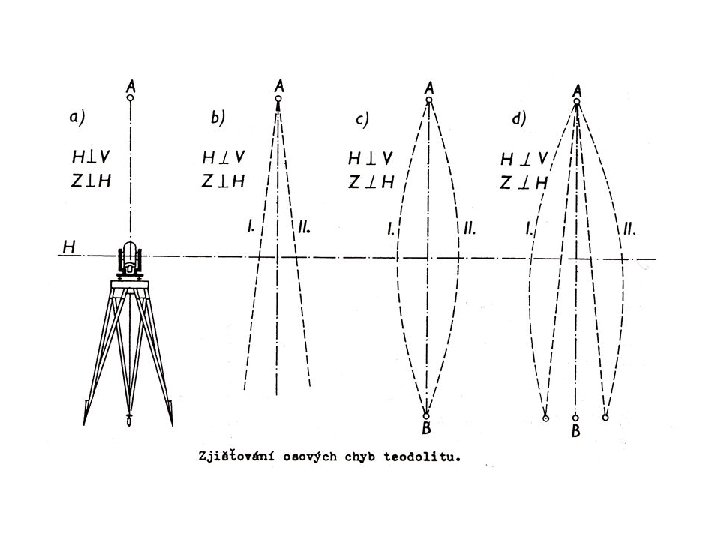
Requirements for the axes 1. L V 2. Z H 3. H V Fulfilment of these requirements has to be tested an adjustment of the instrument has to be performed if it is necessary. 11
ad 1. if this requirement is not fulfilled, the alidade level has to be adjusted ad 2. if it is not realized collimation error measurement of horizontal angles in both positions of the telescope is used to avoid this error ad 3. if it is not realized error in incline measurement of horizontal angles in both positions of the telescope is used to avoid this error 12
Errors in the construction of a theodolite • an excentricity of the alidade – the axis V does not go through the centre of the horizontal circle. • an irregular dividing of the horizontal circle This error is not important at modern instruments. 14
Errors caused by standing of the instrument or the target • • wrong levelling of the instrument wrong centering of the target unstable tripod of the instrument It is not possible to avoid these errors by procedure of the measurement. 15
Errors caused by the observer • pointing error It depends on features of the telescope and the target, on the atmospheric conditions and on abilities of the observer. • reading error It depends on the least division of the reading scale and on the visual acuity of the observer. 16
Pointing 17
Measurement of a horizontal angle in one set 18
Procedure face left position 1. P 1 2. P 2 change the position of the telescope face right position 3. P 2 4. P 1 19
20
Measurement of directions set in one set with repeated pointing at the first point 21
Measurement of zenith angles A horizontal angle is the difference between two directions which are read on the horizontal circle (the difference between the left and the right target). A zenith angle is read on the vertical circle after pointing at a target (the direction to the zenith is given vertical). 22
The vertical circle rotates with tilting of the telescope and indexes of the reading scale are (or should be) in horizontal position during a measurement of the zenith angle. The correct position of the indexes is ensured by • collimation (index) level – older types of theodolites, • compensator – it works automatically (modern instruments). 23
The mentioned requirements for axes of theodolite have to be fulfilled during a measurement of zenith angles too. In addition to these requirements, a reading on the vertical circle should be 100 gon if the line of sight is horizontal. There is so-called index error if this requirement is not fulfilled. It is possible to avoid this error by measurement in both positions of the telescope and by calculation of a correction. 24
Measurement of a zenith angle in both positions of the telescope 25
If there is no index error, then z 1 + z 2 = 400 g If there is an index error, then z 1 + z 2 = 400 g + 2 i and the corrected zenith angle z = z 1 – i 26
27
Electronic theodolites • battery-powered (internal or external) • measured values are on the display (digital form) • some instruments have a built-in compensator of the alidade axis position • the correction of the index error can be introduced to measured values automatically • therefore it is often possible to measure only in the face left position of the telescope 28
• measured values can be recorded to the memory of the instrument • there are function buttons for setting of an arbitrary value of the horizontal circle reading, buttons for units option etc. • descriptive or numeral information can be inserted in memory of some instruments • some of the most modern instruments are motorized and then automatic pointing of the instrument is possible 29
Electronic theodolites 30