Angles and Directions Vertical angles plus or minus


 200 o 50/")
 N 45 o")
 Azimuths : (a) 200")
 Bearings : (a) N")


 = distance(H) cos α Departure (ΔX) = distance(H) cos α Latitude")


 Balance the field angles b) Compute the bearings or Azimuths c)")
- Slides: 43
Angles and Directions
Vertical angles: plus or minus vertical angle Zenith angles : directly above the observe Nadir angles : directly below the observer
HORIZONTAL ANGLES horizontal angles are usually measured with a theodolite or total station. For all closed polygons of n sides, the sum of the interior angles will be (n - 2)1800 n n n Interior angles Exterior angles Deflection angles
TRAVERSES A traverse is essentially a series of straight lines connecting points along the path of a survey. The lengths and directions of the lines are measured in the field, and the positions or co-ordinates of the points computed. These points, called traverse stations, are commonly marked with wooden pegs, stakes, nails or iron pipes.
TRAVERSING Traversing is a rapid convenient method for establishing control. The main purposes of traverses are: • 1 Property surveys to locate and establish boundaries • 2 Supplementary horizontal control for topographic mapping surveys • 3 Location and construction layout surveys for highways, railways, and other private or public works control, is a set of reference-points of known geospatial coordinates. it may consist of any known point capable of establishing accurate control of distance and direction (i. e. coordinates, elevation, bearings, etc. ).
TRAVERSING Traverse networks have many advantages, including: 1 Less reconnaissance and organization needed 2 traverse can change to any shape and thus can accommodate a great deal of different terrains; 3 Traverse networks are free of the strength of figure considerations that happen in triangular systems control, 4 Scale error does not add up as the traverse is performed
DIRECTIONS Azimuth is the direction of a line as given by an angle measured clockwise (usually) from the north end of a meridian. Bearing is the direction of a line as given by the acute angle between the line and a meridian. The bearing angle, which can be measured clockwise or counterclockwise from the north or south end of the meridian. is always accompanied by letters that locate the quadrant in which the line falls (NE, NW, SE, or SW).
TRAVERSES – OPEN TRAVERSES • Open traverses originate at a point of known position and end at a point of unknown position. • No computational checks are therefore possible to detect any errors or blunders in distances or direction. • Open traverses are very risky and should be avoided
TRAVERSES – CLOSED TRAVERSES Closed traverses start and end on points of known position. Since the beginning and end points are known, this provides a computational check on the measurements and calculations. Systematic errors and blunders can be detected in both the distance and directions. In addition to providing known positions for the start and end points, at least one known bearing or azimuth is also provided for closed traverses. More than one bearing is required to prevent the entire traverse from ‘pivoting’ about a single known point.
TRAVERSES – LOOP TRAVERSES A traverse that starts and ends on the same point is called a loop traverse. If the point is known, then it is closed loop traverse. Loop traverses are geometrically and mathematically closed, so it is therefore possible to provide a mathematical check on the sum of the internal angles of the traverse. For a closed polygon (internal angles) = (n – 2) 180 where n is the number of angles measured.
TRAVERSES – LINK TRAVERSES A traverse that starts and ends on different points is called a link traverse. Link traverses can also be either open, starting on a known point and ending on an unknown point, or closed, starting and ending on two different known points. In addition to the known points, closed link traverses also have starting and closing known bearings. Closed-links are geometrically open but mathematically closed.
CLOSED TRAVERSE
OPEN TRAVERSE
AZIMUTHS
BEARING
RELATIONSHIP BETWEEN BEARING AND AZIMUTH NE Bearing =Azimuth SE Bearing = 180 o – Azimuth SW Bearing = Azimuth – 1800 NW Bearing = 3600 - Azimuth
REVERSE DIRECTIONS Reverse Azimuths Reverse Bearings
REVERSE AZIMUTHS Differ between forward and back azimuth =1800
REVERSE BEARINGS Just reverse the direction not the angle value
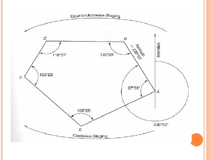
AZIMUTH COMPUTATION When computations are to proceed around the traverse in a clockwise direction, subtract the interior angle from the back azimuth of the previous course. When computations are to proceed around the traverse in a counter-clockwise direction, add the interior angle to the back azimuth of the previous course.
SKETCH FOR AZIMUTH COMPUTATION
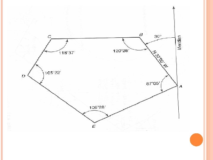
BEARING COMPUTATION Prepare a sketch showing the two traverse lines involved, with the meridian drawn through the angle station. On the sketch, show the interior angle, the bearing angle and the required angle.
SKETCH FOR BEARING COMPUTATION
ANGLE ADJUSTMENTS- CLOSED TRAVERSE
Ex 1 : A closed five sided field traverse has the following interior angles: A= 125 o 25/ 00//, B= 133 o 17/ 00//, C= 80 o 40/ 30//, D= 88 o 10/ 30//, Find the angle at E.
Ex 2 : Convert the following Azimuths to Bearings : (a) 200 o 50/ (b) 133 o 52/ (c) 130 o 13/ (d) 271 o 49/
Ex 3 : Convert the following Bearings to Azimuths : (a) N 45 o 45/ E (b) N 12 o 08/ W (c) S 13 o 11/ E (d) S 77 o 08/ W
Ex 4 : Convert the following Azimuths to reverse (back) Azimuths : (a) 200 o 50/ (b) 133 o 52/ (c) 130 o 13/ (d) 271 o 49/
Ex 5 : Convert the following Bearings to reverse (back) Bearings : (a) N 45 o 45/ E (b) N 12 o 08/ W (c) S 13 o 11/ E (d) S 77 o 08/ W
Ex 6 : Closed traverse ABCD has the following bearings: AB= N 60 o 50/ E BC= S 42 o 48/ E CD= S 7 o 33/ W DA= N 66 o 03/ W Compute the interior angles and provide a geometric check for your work
Interior Angles A= 63 o 47/ 00// B= 140 o 28/ 50// C= 101 o 30/ 20// D= 72 o 48/ 10// E= 161 o 25/ 40// Figure 2
Ex 7 : If the Bearing of AB is N 490 19/ E, compute the bearings for the remaining sides proceeding in a clockwise direction.
Ex 8 : If the Azimuth of AB is 49 o 19/ , compute the azimuths for the remaining sides proceeding in a counterclockwise direction.
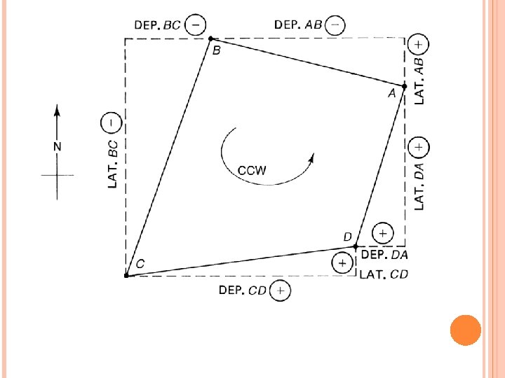
LATITUDES AND DEPARTURES
Latitude (ΔY) = distance(H) cos α Departure (ΔX) = distance(H) cos α Latitude : is the north /south rectangular components of the line(ΔN). Departure : is the east /west rectangular components of the line(ΔE).
COMPASS RULE – DISTRIBUTES THE ERRORS IN LAT/DEP. C lat AB= Σ lat AB P C dep AB = Σ dep AB P The sign of correction is opposite from that of the error
EXAMPLE 9 A five-sided closed field traverse has the following angles Determine the angular error of closure and balance the angles by applying equal corrections to each angle.
EXAMPLE 10 A four-sided closed traverse has the following angles. The lengths of the sided are as follows: AB= 636. 45 m BC= 654. 45 m CD= 382. 65 m DA= 469. 38 m The bearing of AB is S 17 o 17/ W BC is in the NE quadrant
EXAMPLE 10 a) Balance the field angles b) Compute the bearings or Azimuths c) Compute the latitudes and departures d)Determine the linear error of closure and the accuracy ratio.