Angle Exponential Modulation Dr Amit Mishra Historical Background
 Modulation Dr. Amit Mishra")
Angle (Exponential) Modulation Dr. Amit Mishra

Historical Background
 as, Note that when")
Concept of Instantaneous Frequency If we rewrite, Eq. (5. 1) as, Note that when

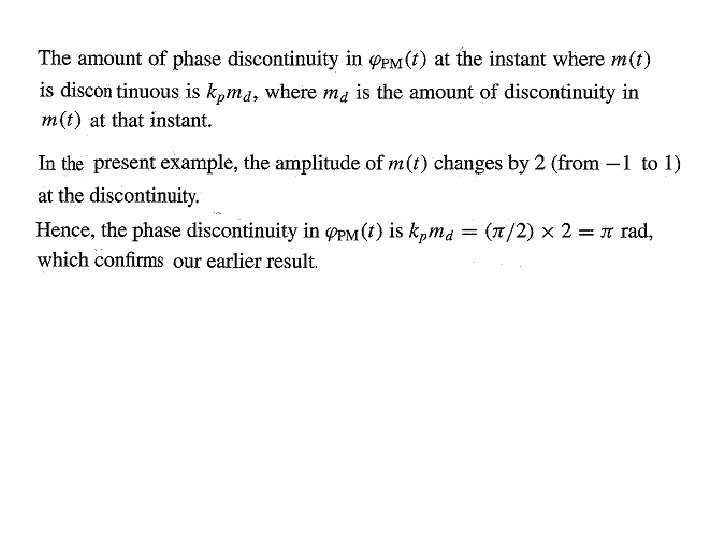
The function are known as the instantaneous phase deviation and instantaneous radian frequency deviation of is called the maximum (or peak) radian frequency deviation of the angle-modulated signal.

Phase and Frequency Modulation

We have:

We know that: Instantaneous radian frequency:

Waveforms:

Phase Modulation

Frequency Modulation

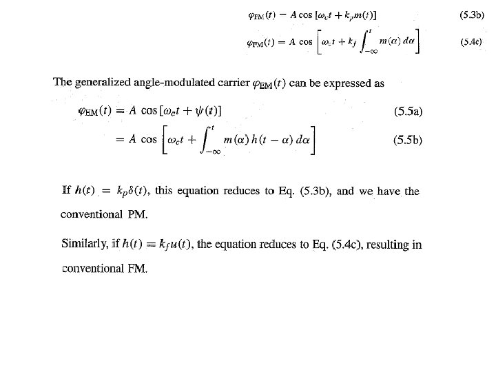
Generalized Concept of Angle Modulation Fig. 5. 2

Fig. Generalized exponential modulation

Example Fig. 5. 4

Solution Given:
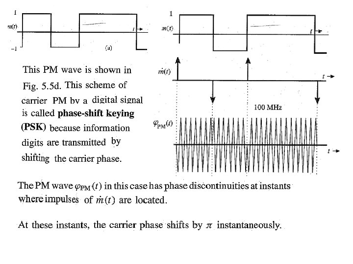
 Derivative of m(t)")
m(t) Derivative of m(t)

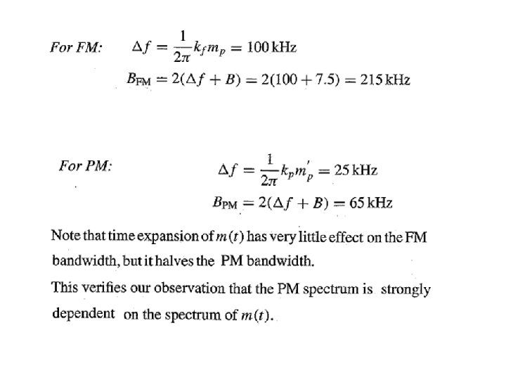
Example Fig. 5. 5

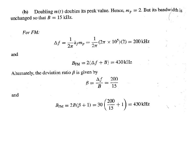
Solution For- FM Given:

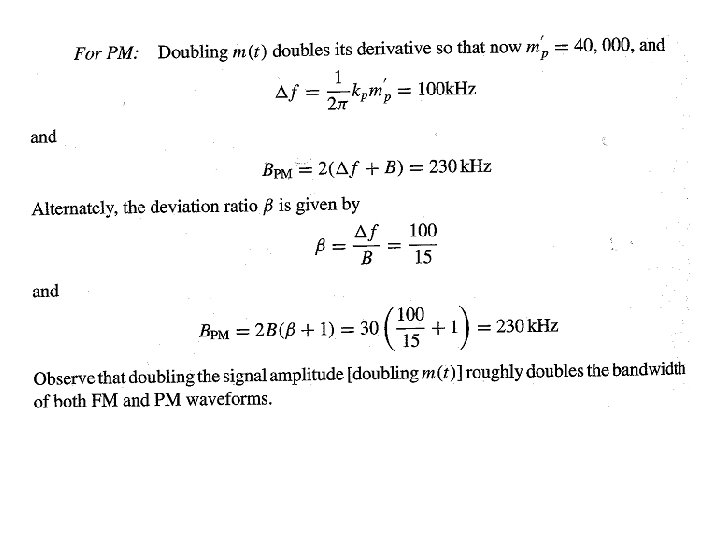
For- PM Given:

Power of an Angle-Modulated Wave

Bandwidth of Angle-Modulated Waves We have: We know that:

Narrow-Band Wide-Band Angle Modulation Angle modulation: Nonlinear

How to make FM linear:

We have: Similarly :

Narrow-Band PM generation Fig 5. 6

Narrow-Band FM generation Fig 5. 6
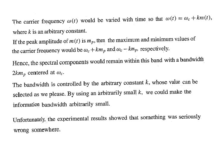
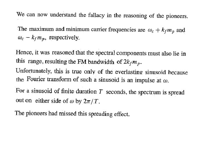
 : The Fallacy Exposed Explanation: Fig 5. 7")
Wide-band FM (WBFM) : The Fallacy Exposed Explanation: Fig 5. 7

We know this: We have

where:

In AM:
)")
Bandwidth (Wide-band FM (WBFM))

BW seems large due to approximation involved in analysis: Adjustment in BW: We have:

Carson’s rule:

Phase Modulation

Example Fig 5. 4 a

Solution: Band width is not given. How to evaluate? :

We have:

We have:

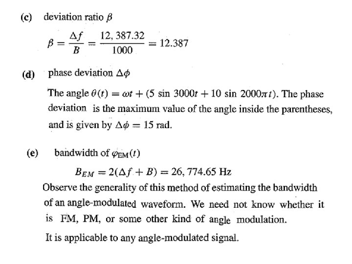
Example

Solution:

Example

Solution:

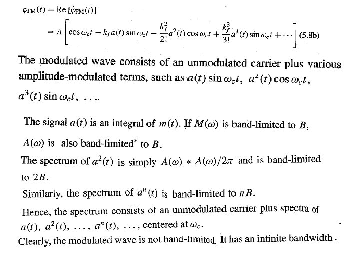
Features of Angle Modulation: Effect of Nonlinearity
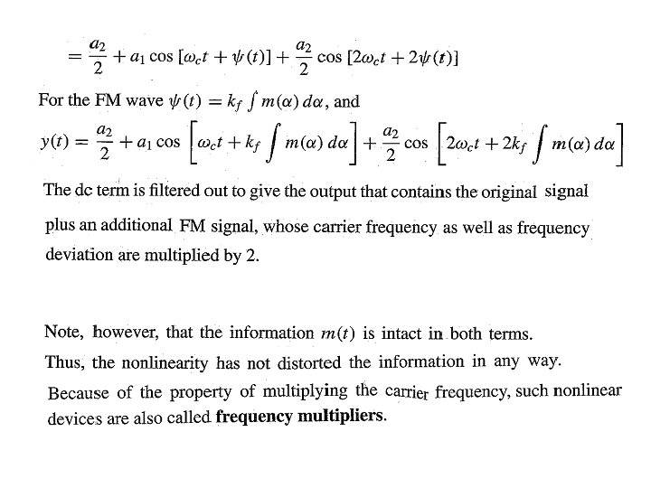

Similarly for nth order case:

Amplitude Modulation: Effect of Nonlinearity

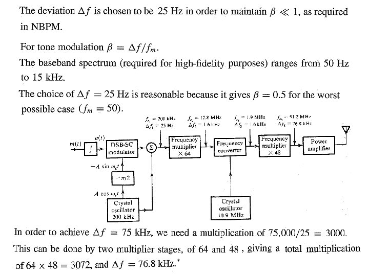
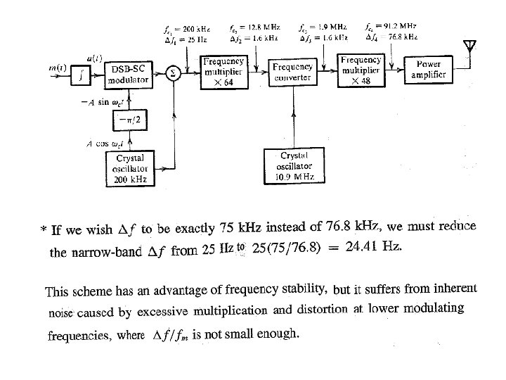
Generation of FM Waves Indirect Method of Armstrong Fig 5. 6

Fig 5. 10

Fig 5. 10 Example:

Direct Generation of FM Method-I: VCO method Method-II: Varactor method Method-I : VCO Method

VCO using Op. Amps

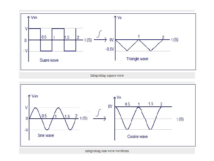
Integrator using Op. Amps

VCO using Op. Amps

Working Operation: This circuit is a voltage-controlled oscillator, which is an oscillator whose frequency is determined by a control voltage. A 10 Hz sawtooth oscillator provides the control voltage in this case; this causes the frequency to rise slowly until it hits a maximum and then falls back to the starting frequency. The first op-amp is an integrator. A voltage divider puts the + input at half the control voltage. The op-amp attempts to keep its – input at the same voltage, which requires a current flow across the 100 k to ensure that its voltage drop is half the control voltage. When the MOSFET at the bottom is on, the current from the 100 k goes through the MOSFET. Since the 49. 9 k resistor has the same voltage drop as the 100 k but half the resistance, it must have twice as much current flowing through it. The additional current comes from the capacitor, charging it, so the first op-amp must provide a steadily rising output voltage to source this current.

When the MOSFET at the bottom is off, the current from the 100 k goes through the capacitor, discharging it, so a steadily falling output voltage is needed from the first op-amp. The third scope shows the output voltage; it looks like a triangle wave. The second op-amp is a Schmitt trigger. It takes the triangle wave as input. When the input voltage rises above threshold of 3. 33 V, it outputs 5 V and the threshold voltage falls to 1. 67 V. When the input voltage falls below that, the output goes to 0 V and the threshold moves back up. The output is a square wave. It's connected to the MOSFET, causing the integrator to raise or lower its output voltage as needed.

Method-II : Varactor method
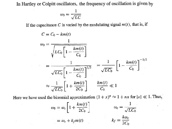

We know: Difficulty in FM generation using Direct Method

Demodulation of FM Method: Using Ideal differentiator

FM Detector using Differentiator:

Problem encountered during detection of FM: Amplitude should not vary :

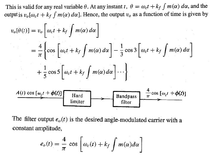
Solution: Bandpass limiter
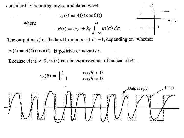

HINT: Fourier Series

Preemphasis and Deemphasis in FM Broadcasting Fig. 5. 16
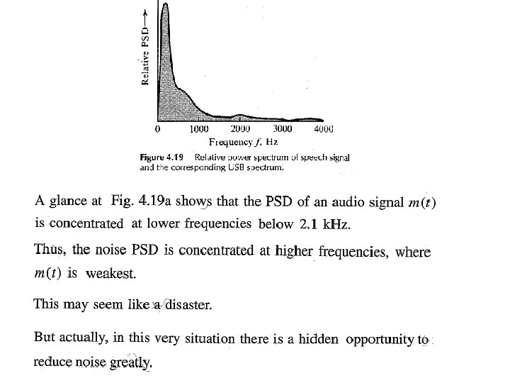

Fig. 5. 17

Preempasis and De-emphasis Filters

Reason of noise reduction

FM Receiver

Monophonic and Stereophonic broadcast
")
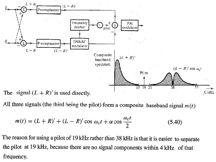
Generation of composite baseband signal and FM Transmission (for Stereophonic and monophonic broadcasting)
")
FM Receiver (for Stereophonic and monophonic broadcasting)
 Fig. 5. 10")
FM Receiver: Fig. 4. 28 AM Receiver (analogous to FM receiver) Fig. 5. 10 FM Transmitter
- Slides: 92