Analysis Phase Requirement Engineering Outline Problems with requirements

Analysis Phase / Requirement Engineering

Outline - Problems with requirements practices - Requirements engineering tasks - Inception Elicitation Elaboration Negotiation Specification Validation Requirements management

The Problems with our Requirements Practices • We have trouble understanding the requirements that we do acquire from the customer • We often record requirements in a disorganized manner • We spend far too little time verifying what we do record • We allow change to control us, rather than establishing mechanisms to control change • Most importantly, we fail to establish a solid foundation for the system or software that the user wants built (more on next slide)
 • Many software developers argue that –")
The Problems with our Requirements Practices (continued) • Many software developers argue that – Building software is so compelling that we want to jump right in (before having a clear understanding of what is needed) – Things will become clear as we build the software – Project stakeholders will be able to better understand what they need only after examining early iterations of the software – Things change so rapidly that requirements engineering is a waste of time – The bottom line is producing a working program and that all else is secondary • All of these arguments contain some truth, especially for small projects that take less than one month to complete • However, as software grows in size and complexity, these arguments begin to break down and can lead to a failed software project

A Solution: Requirements Engineering • Begins during the communication activity and continues into the modeling activity • Builds a bridge from the system requirements into software design and construction • Allows the requirements engineer to examine – – the context of the software work to be performed the specific needs that design and construction must address the priorities that guide the order in which work is to be completed the information, function, and behavior that will have a profound impact on the resultant design

Requirements Engineering Tasks • Seven distinct tasks – – – – Inception Elicitation Elaboration Negotiation Specification Validation Requirements Management • Some of these tasks may occur in parallel and all are adapted to the needs of the project • All strive to define what the customer wants • All serve to establish a solid foundation for the design and construction of the software

Inception Elicitation Elaboration Negotiation Specification Validation Requirements Management

Inception Task • During inception, the requirements engineer asks a set of questions to establish… – – A basic understanding of the problem The people who want a solution The nature of the solution that is desired The effectiveness of preliminary communication and collaboration between the customer and the developer • Through these questions, the requirements engineer needs to… – – Identify the stakeholders Recognize multiple viewpoints Work toward collaboration Break the ice and initiate the communication

The First Set of Questions These questions focus on the customer, other stakeholders, the overall goals, and the benefits • • Who is behind the request for this work? Who will use the solution? What will be the economic benefit of a successful solution? Is there another source for the solution that you need?

The Next Set of Questions These questions enable the requirements engineer to gain a better understanding of the problem and allow the customer to voice his or her perceptions about a solution • How would you characterize "good" output that would be generated by a successful solution? • What problem(s) will this solution address? • Can you show me (or describe) the business environment in which the solution will be used? • Will special performance issues or constraints affect the way the solution is approached?

The Final Set of Questions These questions focus on the effectiveness of the communication activity itself • Are you the right person to answer these questions? Are your answers "official"? • Are my questions relevant to the problem that you have? • Am I asking too many questions? • Can anyone else provide additional information? • Should I be asking you anything else?

Inception Elicitation Elaboration Negotiation Specification Validation Requirements Management

Elicitation Task • Eliciting requirements is difficult because of – Problems of scope in identifying the boundaries of the system or specifying too much technical detail rather than overall system objectives – Problems of understanding what is wanted, what the problem domain is, and what the computing environment can handle (Information that is believed to be "obvious" is often omitted) – Problems of volatility because the requirements change over time • Elicitation may be accomplished through two activities – Collaborative requirements gathering – Quality function deployment

Basic Guidelines of Collaborative Requirements Gathering • Meetings are conducted and attended by both software engineers, customers, and other interested stakeholders • Rules for preparation and participation are established • An agenda is suggested that is formal enough to cover all important points but informal enough to encourage the free flow of ideas • A "facilitator" (customer, developer, or outsider) controls the meeting • A "definition mechanism" is used such as work sheets, flip charts, wall stickers, electronic bulletin board, chat room, or some other virtual forum • The goal is to identify the problem, propose elements of the solution, negotiate different approaches, and specify a preliminary set of solution requirements

Quality Function Deployment • This is a technique that translates the needs of the customer into technical requirements for software • It emphasizes an understanding of what is valuable to the customer and then deploys these values throughout the engineering process through functions, information, and tasks • It identifies three types of requirements – Normal requirements: These requirements are the objectives and goals stated for a product or system during meetings with the customer – Expected requirements: These requirements are implicit to the product or system and may be so fundamental that the customer does not explicitly state them – Exciting requirements: These requirements are for features that go beyond the customer's expectations and prove to be very satisfying when present
 • The basic idea of QFD is to construct relationship matrices")
QFD process (1) • The basic idea of QFD is to construct relationship matrices between customer needs, technical requirements, priorities and (if needed) competitor assessment. • To achieve this the following process is prescribed: 1. 2. 3. 4. 5. 6. Identify stakeholder’s attributes or requirements Identify technical features of the requirements Relate the requirements to the technical features Conduct an evaluation of competing products Evaluate technical features and specify a target value for each feature Prioritize technical features for development effort.
 2 How’s Competitive weighting Importance weighting What’s 3 Relationship matrix Target")
QFD process (2) 2 How’s Competitive weighting Importance weighting What’s 3 Relationship matrix Target values 1 Competitive eval. Importance weighting 6 5 4

http: //wiki. ece. cmu. edu/ddl/index. php/Automatic_can_opener_redesign

Benefits of QFD • • Improves user involvement Improves management support and involvement Shortens the development lifecycle Improves project development Supports team involvement Structures communication processes Provides a preventive tool for improving quality Avoids loss of information

Summary • Problems with requirement engineering • Requirement engineering process • Inception • Elicitation

Elicitation Work Products • • The work products will vary depending on the system, but should include one or more of the following items A statement of need and feasibility A bounded statement of scope for the system or product A list of customers, users, and other stakeholders who participated in requirements elicitation A description of the system's technical environment A list of requirements (organized by function) and the domain constraints that apply to each A set of preliminary usage scenarios (in the form of use cases) that provide insight into the use of the system or product under different operating conditions Any prototypes developed to better define requirements

Inception Elicitation Elaboration Negotiation Specification Validation Requirements Management

Goals of Analysis Modeling • • • Provides the first technical representation of a system Is easy to understand maintain Deals with the problem of size by partitioning the system Uses graphics whenever possible Differentiates between essential information versus implementation information • Helps in the tracking and evaluation of interfaces • Provides tools other than narrative text to describe software logic and policy

Analysis Rules of Thumb • The analysis model should focus on requirements that are visible within the problem or business domain – The level of abstraction should be relatively high • Each element of the analysis model should add to an overall understanding of software requirements and provide insight into the following – Information domain, function, and behavior of the system • The model should delay the consideration of infrastructure and other non-functional models until the design phase – First complete the analysis of the problem domain • The model should minimize coupling throughout the system – Reduce the level of interconnectedness among functions and classes • The model should provide value to all stakeholders • The model should be kept as simple as can be

Analysis Modeling Approaches • Structured analysis – Considers data and the processes that transform the data as separate entities – Data is modeled in terms of only attributes and relationships (but no operations) – Processes are modeled to show the 1) input data, 2) the transformation that occurs on that data, and 3) the resulting output data • Object-oriented analysis – Focuses on the definition of classes and the manner in which they collaborate with one another to fulfill customer requirements

Elements of the Analysis Model Object-oriented Analysis Structured Analysis Scenario-based modeling Flow-oriented modeling Use case text Use case diagrams Activity diagrams Swim lane diagrams Class-based modeling Class diagrams Analysis packages CRC models Collaboration diagrams Data structure diagrams Data flow diagrams Control-flow diagrams Processing narratives Behavioral modeling State diagrams Sequence diagrams

Elements of the Analysis Model • Scenario-based elements – Describe the system from the user's point of view using scenarios that are depicted in use cases and activity diagrams • Class-based elements – Identify the domain classes for the objects manipulated by the actors, the attributes of these classes, and how they interact with one another; they utilize class diagrams to do this • Behavioral elements – Use state diagrams to represent the state of the system, the events that cause the system to change state, and the actions that are taken as a result of a particular event; can also be applied to each class in the system • Flow-oriented elements – Use data flow diagrams to show the input data that comes into a system, what functions are applied to that data to do transformations, and what resulting output data are produced

Scenario-Based Modeling

Developing Use Cases • Step One – Define the set of actors that will be involved in the story – Actors are people, devices, or other systems that use the system or product within the context of the function and behavior that is to be described – Actors are anything that communicate with the system or product and that are external to the system itself • Step Two – Develop use cases, where each one answers a set of questions (More on next slide)
,")
Questions Commonly Answered by a Use Case • • Who is the primary actor(s), the secondary actor(s)? What are the actor’s goals? What preconditions should exist before the scenario begins? What main tasks or functions are performed by the actor? What exceptions might be considered as the scenario is described? What variations in the actor’s interaction are possible? What system information will the actor acquire, produce, or change? Will the actor have to inform the system about changes in the external environment? • What information does the actor desire from the system? • Does the actor wish to be informed about unexpected changes?

Use-case Diagram Use-case diagram for surveillance function

Alternative Actions • Can the actor take some other action at this point? • Is it possible that the actor will encounter some error condition at this point? • Is it possible that the actor will encounter behavior invoked by some event outside the actor’s control?

Activity diagram for Access camera surveillance—display camera views function

Swimlane diagram

Flow-Oriented Modeling

Guidelines • Depict the system as single bubble in level 0. • Carefully note primary input and output. • Refine by isolating candidate processes and their associated data objects and data stores. • Label all elements with meaningful names. • Maintain information conformity between levels. • Refine one bubble at a time.

Data Flow Diagram Context-level DFD for Safe. Home security function
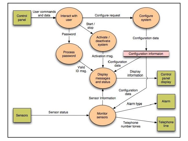

Level 2 DFD that refines the monitor sensors process

Control Flow Diagram State diagram for Safe. Home security function

Processing narrative • The Safe. Home security function enables the homeowner to configure the security system when it is installed, monitors all sensors connected to the security system, and interacts with the homeowner through the Internet, a PC, or a control panel. • During installation, the Safe. Home PC is used to program and configure the system. Each sensor is assigned a number and type, a master password is programmed for arming and disarming the system, and telephone number(s) are input for dialing when a sensor event occurs. • When a sensor event is recognized, the software invokes an audible alarm attached to the system. After a delay time that is specified by the homeowner during system configuration activities, the software dials a telephone number of a monitoring service, provides information about the location, reporting the nature of the event that has been detected. The telephone number will be redialed every 20 seconds until a telephone connection is obtained. • The homeowner receives security information via a control panel, the PC, or a browser, collectively called an interface. The interface displays prompting messages and system status information on the control panel, the PC, or the browser window. Homeowner interaction takes the following form…

Class-based Modeling
 2) 3) 4) 5) 6) 7) Perform a grammatical parse")
Identifying Analysis Classes 1) 2) 3) 4) 5) 6) 7) Perform a grammatical parse of the problem statement or use cases Classes are determined by underlining each noun or noun clause A class required to implement a solution is part of the solution space A class necessary only to describe a solution is part of the problem space A class should NOT have an imperative procedural name (i. e. , a verb) List the potential class names in a table and "classify" each class according to some taxonomy and class selection characteristics A potential class should satisfy nearly all (or all) of the selection characteristics to be considered a legitimate problem domain class Potential classes General classification (More on next slide) Selection Characteristic s

Grammatical Parse • The Safe. Home security function enables the homeowner to configure the security system when it is installed, monitors all sensors connected to the security system, and interacts with the homeowner through the Internet, a PC, or a control panel. • During installation, the Safe. Home PC is used to program and configure the system. Each sensor is assigned a number and type, a master password is programmed for arming and disarming the system, and telephone number(s) are input for dialing when a sensor event occurs. • When a sensor event is recognized, the software invokes an audible alarm attached to the system. After a delay time that is specified by the homeowner during system configuration activities, the software dials a telephone number of a monitoring service, provides information about the location, reporting the nature of the event that has been detected. The telephone number will be redialed every 20 seconds until a telephone connection is obtained. • The homeowner receives security information via a control panel, the PC, or a browser, collectively called an interface. The interface displays prompting messages and system status information on the control panel, the PC, or the browser window. Homeowner interaction takes the following form…

Grammatical Parse • The Safe. Home security function enables the homeowner to configure the security system when it is installed, monitors all sensors connected to the security system, and interacts with the homeowner through the Internet, a PC, or a control panel. • During installation, the Safe. Home PC is used to program and configure the system. Each sensor is assigned a number and type, a master password is programmed for arming and disarming the system, and telephone number(s) are input for dialing when a sensor event occurs. • When a sensor event is recognized, the software invokes an audible alarm attached to the system. After a delay time that is specified by the homeowner during system configuration activities, the software dials a telephone number of a monitoring service, provides information about the location, reporting the nature of the event that has been detected. The telephone number will be redialed every 20 seconds until a telephone connection is obtained. • The homeowner receives security information via a control panel, the PC, or a browser, collectively called an interface. The interface displays prompting messages and system status information on the control panel, the PC, or the browser window. Homeowner interaction takes the following form…
 • General classifications for a potential class – – –")
Identifying Analysis Classes (continued) • General classifications for a potential class – – – – External entity (e. g. , another system, a device, a person) Thing (e. g. , report, screen display) Occurrence or event (e. g. , movement, completion) Role (e. g. , manager, engineer, salesperson) Organizational unit (e. g. , division, group, team) Place (e. g. , manufacturing floor, loading dock) Structure (e. g. , sensor, vehicle, computer) (More on next slide)

Class Selection Criteria 1. 2. 3. 4. 5. 6. Retained information Needed services Multiple attributes Common operations Essential requirements

Identifying Classes Potential class Classification Accept / Reject homeowner role; external entity reject: 1, 2 fail sensor external entity accept control panel external entity accept installation occurrence reject (security) system thing accept number, type not objects, attributes reject: 3 fails master password thing reject: 3 fails telephone number thing reject: 3 fails sensor event occurrence accept audible alarm external entity accept: 1 fails monitoring service organizational unit; ee reject: 1, 2 fail

Defining Attributes of a Class • Attributes of a class are those nouns from the grammatical parse that reasonably belong to a class • Attributes hold the values that describe the current properties or state of a class • An attribute may also appear initially as a potential class that is later rejected because of the class selection criteria • In identifying attributes, the following question should be answered – What data items (composite and/or elementary) will fully define a specific class in the context of the problem at hand? • Usually an item is not an attribute if more than one of them is to be associated with a class

Defining Operations of a Class • Operations define the behavior of an object • Four categories of operations – Operations that manipulate data in some way to change the state of an object (e. g. , add, delete, modify) – Operations that perform a computation – Operations that inquire about the state of an object – Operations that monitor an object for the occurrence of a controlling event • An operation has knowledge about the state of a class and the nature of its associations • The action performed by an operation is based on the current values of the attributes of a class • Using a grammatical parse again, circle the verbs; then select the verbs that relate to the problem domain classes that were previously identified

Identifying operations • The Safe. Home security function enables the homeowner to configure the security system when it is installed, monitors all sensors connected to the security system, and interacts with the homeowner through the Internet, a PC, or a control panel. • During installation, the Safe. Home PC is used to program and configure the system. Each sensor is assigned a number and type, a master password is programmed for arming and disarming the system, and telephone number(s) are input for dialing when a sensor event occurs. • When a sensor event is recognized, the software invokes an audible alarm attached to the system. After a delay time that is specified by the homeowner during system configuration activities, the software dials a telephone number of a monitoring service, provides information about the location, reporting the nature of the event that has been detected. The telephone number will be redialed every 20 seconds until a telephone connection is obtained. • The homeowner receives security information via a control panel, the PC, or a browser, collectively called an interface. The interface displays prompting messages and system status information on the control panel, the PC, or the browser window. Homeowner interaction takes the following form…

Identifying operations • The Safe. Home security function enables the homeowner to configure the security system when it is installed, monitors all sensors connected to the security system, and interacts with the homeowner through the Internet, a PC, or a control panel. • During installation, the Safe. Home PC is used to program and configure the system. Each sensor is assigned a number and type, a master password is programmed for arming and disarming the system, and telephone number(s) are input for dialing when a sensor event occurs. • When a sensor event is recognized, the software invokes an audible alarm attached to the system. After a delay time that is specified by the homeowner during system configuration activities, the software dials a telephone number of a monitoring service, provides information about the location, reporting the nature of the event that has been detected. The telephone number will be redialed every 20 seconds until a telephone connection is obtained. • The homeowner receives security information via a control panel, the PC, or a browser, collectively called an interface. The interface displays prompting messages and system status information on the control panel, the PC, or the browser window. Homeowner interaction takes the following form…

Class Diagram Class diagram for the system class

Class Diagram Class diagram for Floor. Plan

CRC Modeling A CRC model index card for Floor. Plan class

Class Responsibilities • Distribute system intelligence across classes. • State each responsibility as generally as possible. • Put information and the behavior related to it in the same class. • Localize information about one thing rather than distributing it across multiple classes. • Share responsibilities among related classes, when appropriate.

Class Collaborations • Relationships between classes: – is-part-of — used when classes are part of an aggregate class. – has-knowledge-of — used when one class must acquire information from another class. – depends-on — used in all other cases.

Class Diagrams Top: Multiplicity Bottom: Dependencies

Example Class Box Class Name Component Attributes + component. ID - telephone. Number - component. Status - delay. Time - master. Password - number. Of. Tries Operations + program() + display() + reset() + query() - modify() + call()
 • Association – Represented by a solid line")
Association, Generalization and Dependency (Ref: Fowler) • Association – Represented by a solid line between two classes directed from the source class to the target class – Used for representing (i. e. , pointing to) object types for attributes – May also be a part-of relationship (i. e. , aggregation), which is represented by a diamond-arrow • Generalization – Portrays inheritance between a super class and a subclass – Is represented by a line with a triangle at the target end • Dependency – A dependency exists between two elements if changes to the definition of one element (i. e. , the source or supplier) may cause changes to the other element (i. e. , the client) – Examples • One class calls a method of another class • One class utilizes another class as a parameter of a method

Behavioral Modeling
 2) Identify events found within the use cases and")
Creating a Behavioral Model 1) 2) Identify events found within the use cases and implied by the attributes in the class diagrams Build a state diagram for each class, and if useful, for the whole software system

Identifying Events in Use Cases • An event occurs whenever an actor and the system exchange information • An event is NOT the information that is exchanged, but rather the fact that information has been exchanged • Some events have an explicit impact on the flow of control, while others do not – An example is the reading of a data item from the user versus comparing the data item to some possible value

Building a State Diagram • A state is represented by a rounded rectangle • A transition (i. e. , event) is represented by a labeled arrow leading from one state to another – Syntax: trigger-signature [guard]/activity • The active state of an object indicates the current overall status of the object as is goes through transformation or processing – A state name represents one of the possible active states of an object • The passive state of an object is the current value of all of an object's attributes – A guard in a transition may contain the checking of the passive state of an object

Identifying Events • A use-case is examined for points of information exchange. • The homeowner uses the keypad to key in a four-digit password. The password is compared with the valid password stored in the system. If the password in incorrect, the control panel will beep once and reset itself for additional input. If the password is correct, the control panel awaits further action.

State Diagram State diagram for the Control. Panel class
 for the Safe. Home security function")
Sequence Diagram Sequence diagram (partial) for the Safe. Home security function

Inception Elicitation Elaboration Negotiation Specification Validation Requirements Management

Negotiation Task • During negotiation, the software engineer reconciles the conflicts between what the customer wants and what can be achieved given limited business resources • Requirements are ranked (i. e. , prioritized) by the customers, users, and other stakeholders • Risks associated with each requirement are identified analyzed • Rough guesses of development effort are made and used to assess the impact of each requirement on project cost and delivery time • Using an iterative approach, requirements are eliminated, combined and/or modified so that each party achieves some measure of satisfaction

The Art of Negotiation • • Recognize that it is not competition Map out a strategy Listen actively Focus on the other party’s interests Don’t let it get personal Be creative Be ready to commit

Inception Elicitation Elaboration Negotiation Specification Validation Requirements Management

Specification Task • A specification is the final work product produced by the requirements engineer • It is normally in the form of a software requirements specification • It serves as the foundation for subsequent software engineering activities • It describes the function and performance of a computer-based system and the constraints that will govern its development • It formalizes the informational, functional, and behavioral requirements of the proposed software in both a graphical and textual format

Typical Contents of a Software Requirements Specification • Requirements – – – Required states and modes Software requirements grouped by capabilities (i. e. , functions, objects) Software external interface requirements Software internal data requirements Other software requirements (safety, security, privacy, environment, hardware, software, communications, quality, personnel, training, logistics, etc. ) – Design and implementation constraints • Qualification provisions to ensure each requirement has been met – Demonstration, test, analysis, inspection, etc. • Requirements traceability – Trace back to the system or subsystem where each requirement applies
 template TABLE OF CONTENTS 1. 0 Introduction 1. 1 Purpose")
Software Requirements Specification (SRS) template TABLE OF CONTENTS 1. 0 Introduction 1. 1 Purpose 1. 2 Scope 1. 3 Definitions, Acronyms, and Abbreviations 1. 4 References 1. 5 Overview 2. 0 General Description 2. 1 Product Perspective 2. 2 Product Functions 2. 3 User Characteristics 2. 4 General Constraints 2. 5 Assumptions and Dependencies

SRS template • 3. 0 Specific Requirements – 3. 1 Functional Requirements • 3. 1. 1 Unit Registration 3. 1. 2 Retrieving and Displaying Unit Information 3. 1. 3 Report Generation 3. 1. 4 Data Entry – 3. 2 Design Constraints – 3. 3 Non-Functional Requirements • 3. 3. 1 Security • Appendix A

SRS explained • 1. 0 INTRODUCTION This document specifies all the requirements for – 1. 1 Purpose The purpose of the …is to …. The system should assist …. The intended audience for this document is … This specification describes …. . – 1. 2 Scope This document applies only to …. . . This specification is not concerned with …. .

SRS explained – 1. 3 Definitions, Acronyms, and Abbreviations SRS - Software Requirements Specifications IEEE - Institute of Electrical and Electronic Engineering – 1. 4 Reference [1] IEEE 830 -1993: IEEE Recommended Practice for Software Requirements Specifications" IEEE Standards Collection, IEEE, 1997. – 1. 5 Overview In the following sections of this specification……will be presented. In Section 2, the general product and its functions will be introduced.

SRS explained In Section 3, all detailed requirements will be specified and grouped. In Appendix ……. 2. 0 GENERAL DESCRIPTION 2. 1 Product Perspective This system allows stakeholders to…. . The system will display…. . The system will help …… The system provides information about …. 2. 2 Product Functions The system provides the following functions:

SRS explained – 2. 3 User Characteristics The users of the system are: • Level of Users’ Computer Knowledge • Level of Users’ Business Knowledge • Frequency of Use – 2. 4 General Constraints The system will support …. The system will not allow …… – 2. 5 Assumption and Dependencies This system relies on …… The system must have a satisfactory interface and ……

Section 3 of SRS • 3 SPECIFIC REQUIREMENTS – 3. 1 Functional Requirements • 3. 1. 1 Unit Registration – The unit registration requirements are concerned with functions regarding unit registration which includes students selecting, adding, dropping, and changing a unit. – – SRS-001 (3. 1. 1. 1): The system shall allow the user to register a unit. SRS-002 (3. 1. 1. 2): STS shall allow the user to delete a unit if the user has chosen to drop that unit. – SRS-003 (3. 1. 1. 3): – STS shall check if a unit has been filled by enough registered students.
: – STS shall allow the")
SRS functional egs – SRS-004 (3. 1. 1. 4): – STS shall allow the user to add his/her name to the unit waiting list if the user wants to register in a unit which has been filled already with enough registered students. – SRS-005 (3. 1. 1. 5): – STS shall automatically register the unit for the user who is the first one on the waiting list if a vacancy appears for that unit. – SRS-006 (3. 1. 1. 6): – STS shall allow the user to change practical session(s) within a unit. – SRS-007 (3. 1. 1. 7): – STS shall allow the user to change tutorial session(s) within a unit.

Functional parent reqs broken into many child-reqs. • 3. 1. 2 Retrieving and Displaying Unit Information • The retrieving and displaying requirements are concerned with how information is retrieved and presented to the user. – SRS-014 (3. 1. 2. 1): – The system shall allow users to enter the following selection criteria to retrieve unit information: by unit code, by unit number, by title of unit, by weight of unit (credit points). – OR by unit code (3. 1. 2. 1. 1) , by unit number (3. 1. 2) , by title of unit (3. 1. 2. 1. 3) , by weight of unit (credit points) (3. 1. 2. 1. 4).
 – 3. 2 Design Constraints • • • SRS-031 (3.")
Design Constraints (3. 2) – 3. 2 Design Constraints • • • SRS-031 (3. 2. 1): STS shall store and retrieve persistent data. SRS-032 (3. 2. 2): STS shall support PC and/or UNIX platforms. SRS-033 (3. 2. 3): STS shall be developed using the JAVA programming language
: STS")
Non-functional requirements – 3. 3 Non-Functional Requirements • • SRS-034 (3. 3. 1): STS shall respond to any retrieval in less than 5 seconds. SRS-035 (3. 3. 2): STS shall generate a report within 1 minute. SRS-036 (3. 3. 3): STS shall allow the user to remotely connect to the system. SRS-041 (3. 3. 8): The system will be accompanied by a comprehensive user manual.

Safety and security issues – 3. 5. 3 Security – The security requirements are concerned with security and privacy issues. SRS-029: • VSS shall provide staff ID and password verification protection to protect from unauthorised use of the system. SRS-030: • VSS shall allow the store manager to add, remove and modify staff ID and passwords as required.

Other SRS template for section 3 • 3. Specific Requirements – 3. 1 External Interface Requirements • • 3. 1. 1 User Interfaces 3. 1. 2 Hardware Interfaces 3. 1. 3 Software Interfaces 3. 1. 4 Communication Interfaces – 3. 2 Functional Requirements • 3. 2. 1 Requirement 1 – – 3. 2. 1. 1 Introduction 3. 2. 1. 2 Inputs 3. 2. 1. 3 Processing 3. 2. 1. 4 Outputs • 3. 2. 2 Requirement 2 …. .

Other SRS template for section 3 – 3. 3 Performance Requirements – 3. 4 Design Constraints • 3. 4. 1 Standards Compliance • 3. 4. 2 Hardware Limitations …… – 3. 5 Software System Attributes • • – 3. 6 3. 5. 1 Reliability 3. 5. 2 Availability 3. 5. 3 Security 3. 5. 4 Maintainability 3. 5. 5 Portability 3. 5. 6 Reusability 3. 5. 7 Usability 3. 5. 8 Other Factors …. . Other Requirements • 3. 6. 1 Database • 3. 6. 2 Operations …. .

Inception Elicitation Elaboration Negotiation Specification Validation Requirements Management

Validation Task • During validation, the work products produced as a result of requirements engineering are assessed for quality • The specification is examined to ensure that – all software requirements have been stated unambiguously – inconsistencies, omissions, and errors have been detected and corrected – the work products conform to the standards established for the process, the project, and the product • The formal technical review serves as the primary requirements validation mechanism – Members include software engineers, customers, users, and other stakeholders

Questions to ask when Validating Requirements • Is each requirement consistent with the overall objective for the system/product? • Have all requirements been specified at the proper level of abstraction? That is, do some requirements provide a level of technical detail that is inappropriate at this stage? • Is the requirement really necessary or does it represent an addon feature that may not be essential to the objective of the system? • Is each requirement bounded and unambiguous? • Does each requirement have attribution? That is, is a source (generally, a specific individual) noted for each requirement? (more on next slide)
 • Do any requirements conflict with other")
Questions to ask when Validating Requirements (continued) • Do any requirements conflict with other requirements? • Is each requirement achievable in the technical environment that will house the system or product? • Is each requirement testable, once implemented? – Approaches: Demonstration, actual test, analysis, or inspection • Does the requirements model properly reflect the information, function, and behavior of the system to be built? • Has the requirements model been “partitioned” in a way that exposes progressively more detailed information about the system?

Inception Elicitation Elaboration Negotiation Specification Validation Requirements Management

Requirements Management Task • During requirements management, the project team performs a set of activities to identify, control, and track requirements and changes to the requirements at any time as the project proceeds • Each requirement is assigned a unique identifier • The requirements are then placed into one or more traceability tables • These tables may be stored in a database that relate features, sources, dependencies, subsystems, and interfaces to the requirements • A requirements traceability table is also placed at the end of the software requirements specification

Summary Inception Elicitation Elaboration Negotiation Specification Validation Requirements Management
- Slides: 94