ANALYSIS OF STRUCTURES Aluminium truss Chapter Objectives Determine

ANALYSIS OF STRUCTURES

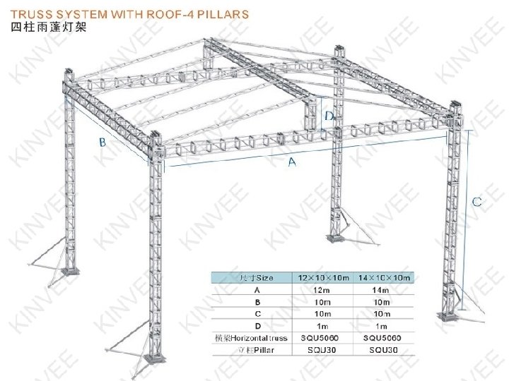
Aluminium truss

Chapter Objectives • Determine the forces in the members of a truss using the method of joints and the method of sections • Analyze forces acting on the members of frames and machines composed of pinconnected members

Chapter Outline 1. Simple Trusses 2. The Method of Joints 3. Zero-Force Members 4. The Method of Sections

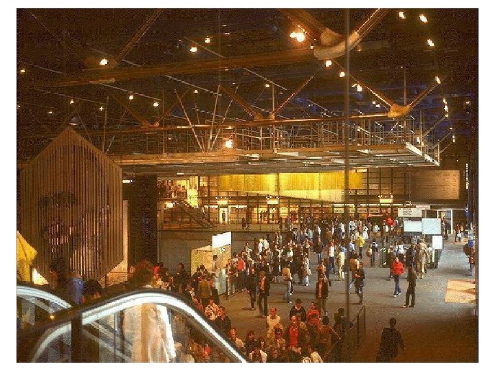
Simple Trusses • A truss composed of slender members joined together at their end points Planar Trusses • Planar trusses used to support roofs and bridges • Roof load is transmitted to the truss at joints by means of a series of purlins

Simple Trusses Planar Trusses • The analysis of the forces developed in the truss members is 2 D • Similar to roof truss, the bridge truss loading is also coplanar

Simple Trusses Assumptions for Design 1. “All loadings are applied at the joint” - Weight of the members neglected 2. “The members are joined together by smooth pins” - Assume connections provided the center lines of the joining members are concurrent

Simple Trusses • Form of a truss must be rigid to prevent collapse • The simplest form that is rigid or stable is a triangle

Method of Sections Method of Joints Trusses

• For truss, we need to know the force in each members • Forces in the members are internal forces • For external force members, equations of equilibrium can be applied • Force system acting at each joint is coplanar and concurrent • ∑Fx = 0 and ∑Fy = 0 must be satisfied for equilibrium

The Method of Joints Procedure for Analysis • Draw the FBD with at least 1 known and 2 unknown forces • Find the external reactions at the truss support • Determine the correct sense of the member • Orient the x and y axes • Apply ∑Fx = 0 and ∑Fy = 0 • Use known force to analyze the unknown forces

Example 1 Determine the force in each member of the truss and indicate whether the members are in tension or compression.

Solution • FBD of each pin shows the effect of all the connected members and external forces applied to the pin • FBD of each member shows only the effect of the end pins on the member

Example 2 Determine the force members HC, CG and DF of the truss. State if the members are in tension or compression. Use joint method of analysis

Example 3 Determine the force members GB, AB of the truss. State if the members are in tension or compression. Use joint method of analysis

Zero-Force Members • Method of joints is simplified using zeroforce members • Zero-force members is supports with no loading • In general, when 3 members form a truss joint, the 3 rd member is a zero-force member provided no external force or support reaction is applied to the joint

Example 4 Using the method of joints, determine all the zero-force members of the Fink roof truss. Assume all joints are pin connected.

Example 5 Using the method of joints, indicate all the members of the truss shown in the figure below that have zero force. A B C H G E F P D

The Method of Sections • Used to determine the loadings within a body • If a body is in equilibrium, any part of the body is in equilibrium • To find forces within members, an imaginary section is used to cut each member into 2 and expose each internal force as external

The Method of Sections • Consider the truss and section a-a as shown • Member forces are equal and opposite to those acting on the other part – Newton’s Law

The Method of Sections Procedure for Analysis Free-Body Diagram • Decide the section of the truss • Determine the truss’s external reactions • Use equilibrium equations to solve member forces at the cut session • Draw FBD of the sectioned truss which has the least number of forces acting on it • Find the sense of an unknown member force

The Method of Sections Procedure for Analysis Equations of Equilibrium • Summed moments about a point • Find the 3 rd unknown force from moment equation

Example 6 Determine the force members HC, CG and DF of the truss. State if the members are in tension or compression. Use joint method of analysis

Example 7 Determine the force members GB, AB of the truss. State if the members are in tension or compression. Use joint method of analysis

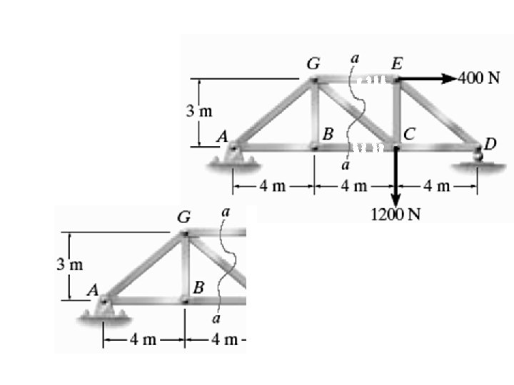
Example 8 Determine the force in members GE, GC, and BC of the truss using sectional method of analysis. Indicate whether the members are in tension or compression.

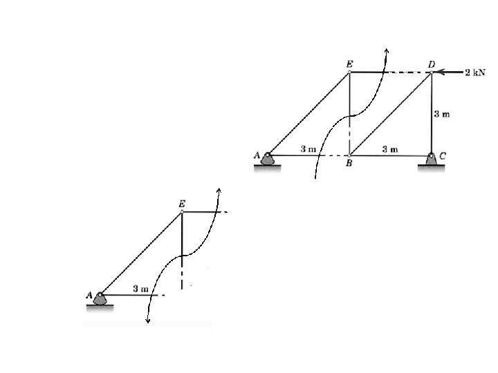
Example 9 Determine the force in members DE, EB, and AB of the truss using sectional method of analysis. Indicate whether the members are in tension or compression
 Determine the force in each member of the truss, and state if")
problem 1) Determine the force in each member of the truss, and state if the members are in tension or compression.
 Determine the force in each member of the truss and state if")
problem 2) Determine the force in each member of the truss and state if the members are in tension or compression. Set P 1 = 2 k. Nand P 2 = 1. 5 k. N.
 Determine the force in members DC, HC, and HI of the truss,")
problem 3) Determine the force in members DC, HC, and HI of the truss, and state if the members are in tension or Compression.
- Slides: 33