ANALYSIS OF STRUCTURE Determine the forces in the


 Trusses: formed from two-force members, i.")


 • • For truss, we need")
 Procedure for Analysis • Draw the")


 G H FBD")


 2.")
- Slides: 52
ANALYSIS OF STRUCTURE • Determine the forces in the members of a truss using the method of joints and the method of sections • Determine the internal forces, shear force and moment in frame • Knowledge Sincerity Excellence
Outline 1. 2. 3. 4. 5. 6. 7. Simple Trusses The Method of Joints Zero-Force Members The Method of Sections Space Trusses Frames and Machines Internal Forces in structural Member – Loading, shear force and moment Copyright © 2010 Pearson Education South Asia Pte Ltd
• For the equilibrium of structures made of several connected parts, the internal forces as well the external forces are considered. • In the interaction between connected parts, Newton’s 3 rd Law states that the forces of action and reaction between bodies in contact have the same magnitude, same line of action, and opposite sense. Copyright © 2010 Pearson Education South Asia Pte Ltd
Three categories of engineering structures are considered: a) Trusses: formed from two-force members, i. e. , straight members with end point connections b) Frames: contain at least one multi-force member, i. e. , member acted upon by 3 or more forces. c) Machines: structures containing moving parts designed to transmit and modify forces. Copyright © 2010 Pearson Education South Asia Pte Ltd
Simple Trusses • A truss composed of slender members joined together at their end points Planar Trusses • • • Planar trusses used to support roofs and bridges Roof load is transmitted/distributed to the truss at joints by means of a series of purlins thus make roof stronger. In a bridge – load is 1 st transmitted to stringers, then floor beams & finally to truss Copyright © 2010 Pearson Education South Asia Pte Ltd
Different types of trusses Copyright © 2010 Pearson Education South Asia Pte Ltd
Simple Trusses Planar Trusses • • The analysis of the forces developed in the truss members is 2 D Similar to roof truss, the bridge truss loading is also coplanar Relationship between member, m and joint, j is: m = 2 j - 3 Copyright © 2010 Pearson Education South Asia Pte Ltd
Simple Trusses Assumptions for Design 1. “All loadings are applied at the joint” - Weight of the members neglected 2. “The members are joined together by smooth pins” - Assume connections provided the center lines of the joining members are concurrent (moment = ZERO) Gusset plate Bolt or pin Copyright © 2010 Pearson Education South Asia Pte Ltd
Simple Trusses Simple Truss • • Form of a truss must be rigid to prevent collapse The simplest form that is rigid or stable is a triangle Triangular Truss Attaching 2 more members to a new joint D forming larger truss Copyright © 2010 Pearson Education South Asia Pte Ltd
Definition of a Truss – in short • A truss consists of straight members connected at joints. No member is continuous through a joint. • Most structures are made of several trusses joined together to form a space framework. Each truss carries those loads which act in its plane and may be treated as a twodimensional structure. Tend to elongate TENSION 6 - 10 • Bolted or welded connections are assumed to be pinned together. Forces acting at the member ends reduce to a single force and no couple. Only two-force members are considered. • When forces tend to pull the member apart, it is in tension. When the forces tend to Tend to shorten – COMPRESSION (member compress the member, it is in compression. thicker)
HOW TO DETERMINE ? - METHODS OF ANALYSIS To design the members and the connections (joints) of a truss, we must determine the force developed in each member when the truss is subjected to a given loading. There are 2 methods of determining forces in the members of a TRUSS: i. Method of Joints ii. Method of Sections
The Method of Joints (8 th Feb 2011) • • For truss, we need to know the force in each members Forces in the members are internal forces For external force members, equations of equilibrium can be applied Force system acting at each joint is coplanar and concurrent (ie. moment is ZERO) & only 2 equations for equilibrium: ∑Fx = 0 and ∑Fy = 0 must be satisfied for equilibrium Copyright © 2010 Pearson Education South Asia Pte Ltd
The Method of Joints (11 th Feb 2011) Procedure for Analysis • Draw the FBD with at least 1 known and 2 unknown forces • Find the external reactions at the truss support • Determine the correct sense of the member eg. Sense of direction - FBC must push on the pin (COMPRESSION) as it’s horizontal component of FBC (FBC sin 45) must balance the 500 N Like wise FBA must in TENSION as it’s vertical component of FBA must balance the vertical component of FBC (FBC cos 45) Copyright © 2010 Pearson Education South Asia Pte Ltd
The Method of Joints Procedure for Analysis …. . continue • • • Orient the x and y axes Apply ∑Fx = 0 and ∑Fy = 0 Use known force to analyze the unknown forces Copyright © 2010 Pearson Education South Asia Pte Ltd
Example 6. 1 Determine the force in each member of the truss and indicate whether the members are in tension or compression. Member in Tension Member in Compression ? ? ? Copyright © 2010 Pearson Education South Asia Pte Ltd
Solution • 2 unknown member forces at joint B and ONE known force • 1 unknown reaction force at joint C • 2 unknown member forces and 2 unknown reaction forces at point A So start at Joint B, (since we should have no more than 2 unknown forces at a joint and at least 1 known force acting there) – BY INSPECTION Copyright © 2010 Pearson Education South Asia Pte Ltd
Solution For Joint C, For Joint A, Copyright © 2010 Pearson Education South Asia Pte Ltd
Solution • FBD of each pin shows the effect of all the connected members and external forces applied to the pin • FBD of each member shows only the effect of the end pins on the member Copyright © 2010 Pearson Education South Asia Pte Ltd
The Method of Joints FBD -FREE BODY DIAGRAM
From the FBD, Taking moment @ which point ?
Zero-Force Members • Method of joints is simplified using zero-force members • Zero-force members are supports with no loading. Use to increase stability of the truss during construction and to provide support if the applied loading is changed • In general, when 3 members form a truss joint, the 3 rd member is a zero-force member provided no external force or support reaction is applied to the joint Copyright © 2010 Pearson Education South Asia Pte Ltd
To find zero-force member – inspect • If only 2 members form a truss joint and no external load or support reaction is applied to the joint, the two members must be zero-force member • If 3 members form a truss joint for which 2 of the members are collinear, the third member is a zero member provided no external force or support is applied to the joint Copyright © 2010 Pearson Education South Asia Pte Ltd
First Condition: If only 2 members form a truss joint and no external load or support reaction is applied to the joint, the two members must be zero-force member Therefore, the load P is only supported by 5 members Copyright © 2010 Pearson Education South Asia Pte Ltd
The secondition: If 3 members form a truss joint for which 2 of the members are collinear, the third member is a zero member provided no external force or support is applied to the joint Copyright © 2010 Pearson Education South Asia Pte Ltd
Therefore, the load P is only supported by 3 members Copyright © 2010 Pearson Education South Asia Pte Ltd
Determine all the zero-force member
Indentify member under Tension and Compression C C T T C C T Copyright © 2010 Pearson Education South Asia Pte Ltd
Determine all the zero-force member C C C T T T C LOOK FOR JOINT GEOMETRICS THAT HAVE 3 MEMBERS IN WHICH 2 ARE COLLINEAR T JOINT G: ∑ Fy = 0; FGC = O If we were to consider joint C (5 unknowns) instead of G, we could not conclude GC is a zero-force member. Since GC is a zero-force member, the 5 k. N load at C must be supported by members CB, CH, CF, CD Copyright © 2010 Pearson Education South Asia Pte Ltd
Determine all the zero-force member C C C T T T C LOOK FOR JOINT GEOMETRICS THAT HAVE 3 MEMBERS IN WHICH 2 ARE COLLINEAR T JOINT D: ∑ Fx = 0; FDF = O Copyright © 2010 Pearson Education South Asia Pte Ltd
Determine all the zero-force member C C C T T T C T JOINT F: ∑ Fy = 0; FFC cos ᶿ = O, Copyright © 2010 Pearson Education South Asia Pte Ltd FFC = 0
Determine all the zero-force member C C C T T T C T NOW LETS LOOK AT JOINT B BEFORE WE EXAMINE JOINT H, IF JOINT B IS ANALYSED: ∑ Fx = 0; 2 k. N - FBH = O, FBH = 2 k. N Copyright © 2010 Pearson Education South Asia Pte Ltd
Determine all the zero-force member C C C T T T C SO FAR FGC & FFC ARE ZERO-FORCE MEMBER T LOOKING AT JOINT H (FFC IS ZERO; is FHC = 0 ? ): ∑ FY = 0; FHC IS NOT ZERO THEREFORE HC IS NOT A ZERO-FORCE MEMBER – SO FORCE 5 k. N is only supported by FHC , FCB & FCD (3 out of 5 members) Copyright © 2010 Pearson Education South Asia Pte Ltd
The zero-force members are: FFC C C T T C FGC C T C Zero-force member FDF T Copyright © 2010 Pearson Education South Asia Pte Ltd
The Method of Sections • • • Used to determine the loadings within a body If a body is in equilibrium, any part of the body is in equilibrium To find forces within members, an imaginary section is used to cut each member into 2 and expose each internal force as external Copyright © 2010 Pearson Education South Asia Pte Ltd
The Method of Sections • • Consider the truss and section a-a as shown Member forces are equal and opposite to those acting on the other part – Newton’s Law Copyright © 2010 Pearson Education South Asia Pte Ltd
6. 4 The Method of Sections Procedure for Analysis Free-Body Diagram • Decide the section of the truss • Determine the truss’s external reactions • Use equilibrium equations to solve member forces at the cut session • Draw FBD of the sectioned truss which has the least number of forces acting on it • Find the sense of an unknown member force - direction Copyright © 2010 Pearson Education South Asia Pte Ltd
6. 4 The Method of Sections Procedure for Analysis Equations of Equilibrium • Summed moments about a point • Find the 3 rd unknown force from moment equation Copyright © 2010 Pearson Education South Asia Pte Ltd
Example 6. 5 Determine the force in members GE, GC, and BC of the truss. Indicate whether the members are in tension or compression. Copyright © 2010 Pearson Education South Asia Pte Ltd
Solution • Choose section a-a since it cuts through the three members It is first necessary to find the • Draw FBD of the entire truss external reaction at A and D G E FBD B C Copyright © 2010 Pearson Education South Asia Pte Ltd
Solution – To find FBC, FGE, FGC • Draw FBD for the section portion ? FBC FGE FGC CUT SECTION G B E C Copyright © 2010 Pearson Education South Asia Pte Ltd FBD
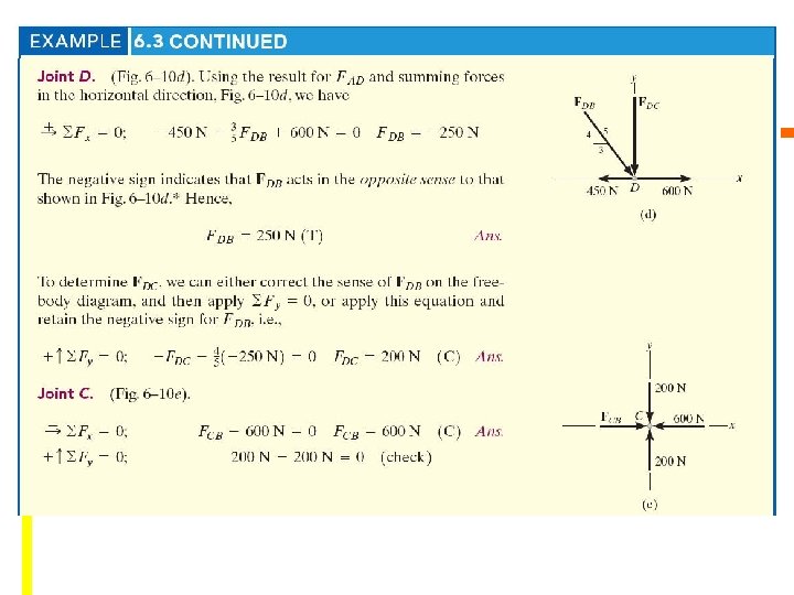
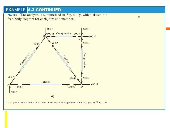
EXAMPLE 6. 6 Copyright © 2010 Pearson Education South Asia Pte Ltd
Cut section
First, we need to determine support reactions (at A & E) G H FBD Ax F A B Ay C 5 k. N D 3 k. N E Ey Take ∑ of Moment about A = 0: Ey x 16 - 3 x 12 – 5 x 8 = 0, Ey = 4. 75 k. N ∑ Fx = 0, Ax = 0 ∑ Fy = 0, Ay – 5 – 3 + Ey = 0, Knowing Ey = 4. 75 k. N, therefore Ay = 3. 75 k. N Copyright © 2010 Pearson Education South Asia Pte Ltd
G H Ax F A B Ay C 5 k. N D 3 k. N E Ey Draw FBD of the right section – as this is easier to analyze. There are three unknowns FFG, FCF and FCD Take ∑ of Moment about O = 0 as this will eliminate unknowns FFG & FCD. How to find point O? use proportional triangles: 4/(4+x) = 6/(8+x), x = 4 m ∑ about O = 0, - FCF sin 45 o x (12 m) + 3 x (8 m) – 4. 75 x (84 m) = 0, FCF = 0. 589 k. N Copyright © 2010 Pearson Education South Asia Pte Ltd
Space Trusses • • • Consists of members joined together at their ends to form 3 D structure The simplest space truss is a tetrahedron Additional members would be redundant in supporting force P Copyright © 2010 Pearson Education South Asia Pte Ltd
Space Trusses Assumptions for Design • • Members of a space truss is treated as 2 force members provided the external loading is at the joints When weight of the member is considered, apply it as a vertical force, half of its magnitude applied at each end of the member Method of Joints – 3 D • • Solve ∑Fx = 0, ∑Fy = 0, ∑Fz = 0 at each joint Force analysis has at least 1 unknown force and 3 unknown forces Copyright © 2010 Pearson Education South Asia Pte Ltd
Space Trusses Method of Sections • When imaginary section is passes through a truss it must satisfied ∑Fx = 0, ∑Fy = 0, ∑Fz = 0 ∑Mx = 0, ∑My = 0, ∑Mz = 0 • By proper selection, the unknown forces can be determined using a single equilibrium equation Copyright © 2010 Pearson Education South Asia Pte Ltd
Machines are structures designed to transmit and modify forces. Their main purpose is to transform input forces into output forces. Free-Body Diagram • Isolate each part by drawing its outlined shape – show all forces and couple moments act on the part – identify each known and unknown force and couple moment – indicate any dimension – apply equations of equilibrium – assumed sense of unknown force or moment – draw FBD Copyright © 2010 Pearson Education South Asia Pte Ltd
Machines • To find the clamping force, Q exerted on wire/pipe if a force of P N is applied • Given the magnitude of P, determine the magnitude of Q. • Create a free-body diagram of the complete machine, including the reaction that the wire exerts. • The machine is a nonrigid structure. Use one of the components as a freebody. • Taking moments about A, 6 - 51
ERT 164 TUTORIAL ANALYSIS OF STRUCTURES 1. Q F 6 -5 (pg 275) 2. Q F 6 -6 (pg 275) 3. Q 6 -8 (pg 277) 4. Q 6 -11 (pg 277) 5. Q F 6 -9 (pg 286) 6. Q 6 -37 (pg 287)