Analysis models and design models ANALYSIS DESIGN Class


 are used to describe the flow of")


- Slides: 27
Analysis models and design models ANALYSIS DESIGN Class Diagrams Use Case Diagrams Package Diagrams Detailed Class Diagrams design Sequence Diagrams Textual descriptions of UC Sequence Diagrams Database schema State Diagrams Activity Diagrams User Interface Component Diagram Deployment Diagram System security and control
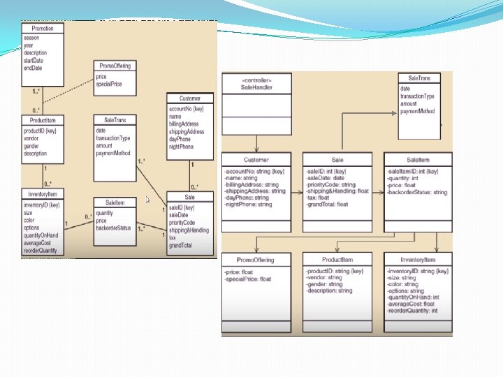
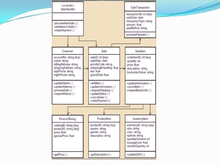
Detailed Class Diagram �Go through the use cases �Select the domain classes that are involved in each use case; Check the preconditions and postconditions for their completion. �Add a controller class to be responsible for the use case �Determine the requirements for navigational visibility �Fill in the attributes of each class with visibility and type �Note: Many times multiplicities are removed from the diagram to focus on navigation, but they can be retained
Visibility of navigation �The ability of an object to see and interact with another object �Achieved by adding to a class a variable reference to an object (object reference variable) �Appears as an arrow at the end of the association - The customer can see and interact with the Sale
Rules for navigability �One-to-many associations that indicate a superiorsubordinate relationship ensure navigation from superior to subordinates �Mandatory associations, in which objects in a class can not exist without objects in another class, usually provide navigation from the most independent to the most dependent class �When an object needs information from another object, you may need a navigation arrow
Class Methods �You can use the CRC - Class, Responsibility, Collaboration cards technique �What are the responsibilities of a class and how it collaborates with other classes to realize the use case �It is obtained through brainstorming �You can use detailed sequence diagrams - each message received by an object of a class must have a corresponding method in that class
CRC examples
Protection against change �A design principle is to separate the parts that are stable from the parties that undergo numerous changes. �Separate the forms and pages in the user interface that have a high probability of changing from the logic of the application. �The connection to the database and SQL logic that are likely to change is kept in separate classes from the application logic �Use adapter classes that can change for interaction with other systems �If you choose between two design variants, choose one that offers greater protection against change
Design of the database �It starts from the class model �The structure of the database is selected �Typically we work with relational databases, but there may be platforms that work with object-oriented databases �Designing the DB architecture (distributed, etc) �Design the schema of the database �Tables and columns in relational model �Design the referential integrity constraints �References through external keys
Designing the interfaces �After completing the use case diagrams and the first stable version of interaction and classes diagrams are developed, it is recommended to implement a prototype of the IT system. This prototype is called interface prototype because it has the role to: �Refine the relationships between actors and interface classes; �Obtain feedback from the client (client) on the visual aspect of the application.
Designing the interfaces �The first step - investigating the actors' expectation on the interface by completing specific questionnaires consisting of the following questions: �What level of training (computer science) the actor requires to achieve a certain functionality? �Does the actor have working experience in windowbased environments? �Does the actor have experience in using other automated process modeling systems? �Is it necessary to consult documents / catalogs in parallel with the use of the application? �Does the actor want to implement 'rescue / restoration' facilities?
Designing the interfaces �The goals of the prototype are: �Setting interface requirements for key application functionalities; �It demonstrates to the client (in a visual form) that the project requirements have been well understood and are achievable; �The start of the development phase of the standard interface elements.
Designing the interfaces �Screen structure maps (charts) are used to describe the flow of the application following the main ways of use. �Representation : �Square shapes for modal window representation (requires a user response to continue an activity). �Square shapes with rounded corners for the representation of non-modal windows �The crossing direction shows the window navigation path.
Windows that contain Tabs Screen structure diagram Main window Class management Search student Search teacher
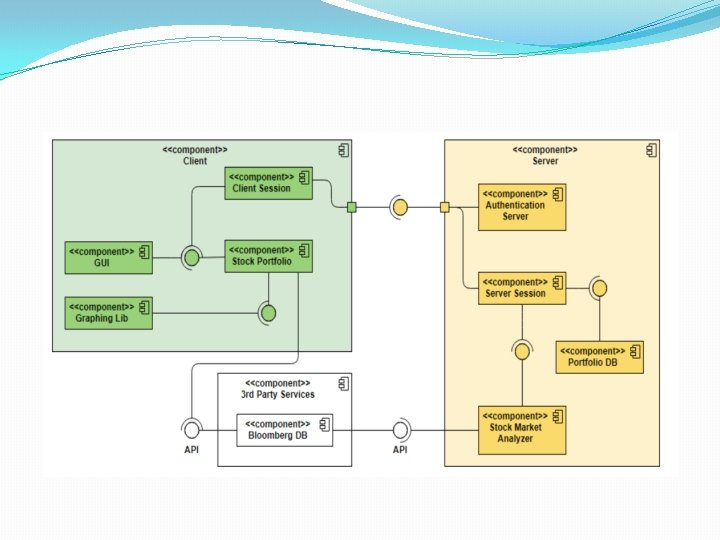
Component diagram �A component diagram shows the dependencies between different software components that make up an IT system. �These dependencies are: �Static - occur in the compilation or link-editing steps �Dynamic - occur during execution �A component is a software module (source code, binary code, dll, executable etc) with a well-defined interface.
Component diagram �Usually, the name of a component is the name of the file represented by the component. �Objects implemented by a component instance are represented graphically inside the component instance symbol. Graphical representation of components in UML
Component diagram �The component diagram is a graph of components between which there are dependency or composition relationships (components physically included in other components). �Component dependencies are graphically represented through interrupted lines between a client component and a service provider component, targeting the vendor component. �The dependency relationship means that the classes included in the client component can inherit, instantiate or use classes included in the vendor component. �There may also be relationships of dependence between components and interfaces of other components, relationships that mean that a client uses vendor component operations
Component diagram �Examples of predefined stereotypes for components: Ø <<Main Program>> Ø <<Sub. Program>> Ø <<Package>> Ø <<DLL>> Ø <<Task>> Ø <<EXE>>
Component diagram example
Deployment diagram �Deployment diagrams show the configuration of the processing elements during execution and the components, processes and objects they contain. �A deployment diagram is a graph of nodes connected through communication associations. �A node is a physical entity that is a processing resource with memory and processing capabilities (computing devices, human resources, mechanical processing resources). �A node is graphically represented by a parallelepiped. A node type has a name associated, and an instance of a node has (optionally) an instance name and a type name (instance name: type name). An association between two nodes indicates the existence of a communication path between nodes.
Deployment diagram �Deployment diagrams can be used to represent components that may belong to certain nodes by embedding the component symbol within the symbol representing the node. �There may also be dependency relationships between components.
Types of nodes �Deployment diagrams may include two type of nodes: devices and execution environments. Ø Devices are computing resources with processing capabilities and the ability to execute programs. Some examples of device nodes include PCs, laptops, and mobile phones. Ø EEN – Execution Environment Node is any computer system that resides within a device node. It could be an operating system, a JVM, or another servlet container, a Web server (Apache or. Microsoft's Internet Information Server (IIS) ).
Components hosted by nodes �Deployment diagrams can be used to represent the components that belong to a node by enlosing the component symbol inside the node symbol.
Deployment diagram example
Deployment diagram example