Analysis and Design of Steel Structure Vertical Farm
 Prepared by: Khansaa Rawajbeh")


 =Take the forest to new heights")


 The space inside the building in helps in ventilation process.")


 bar thickness q high strength q")
 SD 1. 25 LIVE GLSS 2. 5")


 = From IBC 2012 code Δallowable=")
 deflection 2 From IBC 2012 code Δallowable = ��")


:")


 weld only")


- Slides: 54
Analysis and Design of Steel Structure Vertical Farm (Green Sky) Prepared by: Khansaa Rawajbeh Riham Jawabreh Sandy Sabbarini Supervisor: Dr. Mohammad samaneh
Why we choose this idea? Agriculture Future? ? ?
050 + +
Simple Equation (Green Revolution) =Take the forest to new heights
Vertical Farm Vertical Harvesting Growing UP
Combination of : Biotechnology + Engineering + Data Science + +
What plants need to grow? water oxygen sunlight Plant growth By Carefully Controlling the environment Leads To Extend the Growing Season.
Production capacity rate 1 m 2 = 0. 5 acres
produce 20 tons of vegetables every day
water Rain water is collected and then reused it. Theses gardens use up to 2/3 less water.
Introduction: 1. 1. Project Description. Ø Location It is located at east of Nablus Wadi Al-Tuffah. It’s extended over an area 1000 meter square. It consists of two parts of structure one of them have an area of 600 meter square Ø Stories and usage 7 floors Stories 1 Ground floor 2 -7 Agricultural floors Function Area(m 2) Mainly: offices and 600 storage Agriculture 600 containers (50*80 cm) for crops growing Height(m) 4 3
6 5 4 3 2 1 How to solve the problem? Used the same area of the land 6 times , so increase the productivity not just 6 times but more
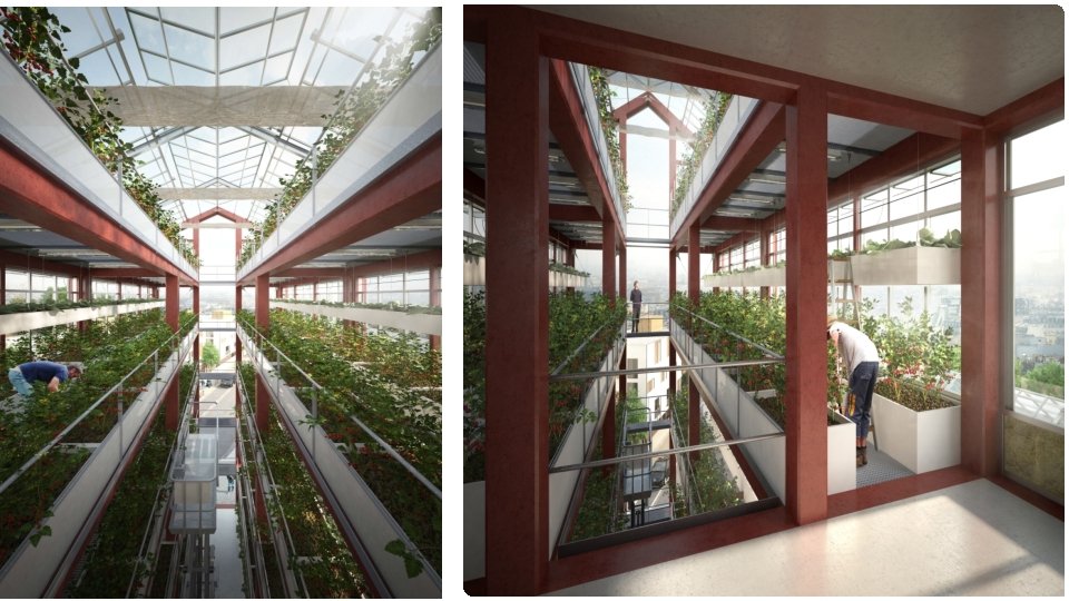
Romainville, Paris
sunlight The space inside the building helps to enter the sunlight and reach all plants.
Ventilation (oxygen) The space inside the building in helps in ventilation process.
Due to ideal growing conditions, plants mature 25% faster and produce 30% more product
Materials used: A 36 STEEL Tensile Strength, Yield 250 MPa
Polycarbonate Sheets They are transparent panels made of distinguished and strong imported materials, which are light, strong, durable and flexible compared to glass Its advantages: • -stability of the color degree • -It is characterized by high light transmittance up to 90%. • -Resistant to mechanical stress • - Lightweight material • - Easy constructed
glass Glass curtain walls are lightweight aluminum-framed facades housing glass or metal panels. gravity loads and wind resistance thickness equals 10 mm
compost soil Ø light Ø high quality of the soil Ø raising production Ø contain a lot of organic fertilizer Ø plants to grow well
steel mesh Steel Floor Grating with (6 mm) bar thickness q high strength q Light structure
Loads in SAP Type of load (KN/M) SD 1. 25 LIVE GLSS 2. 5 1
Steel Sections shown in shop drawings. : • Members Group: Section type Dimensions Columns H- beam HEA 220 I-Beam IPE 270 I-Beam IPE 180 Rafter Beam I-Beam IPE 270 Purlins XZ Bracing TUPE 2 L-Double Angle 120 Tubo 2 L 80× 60× 7× 8 YZ Bracing 2 L-Double Angle 2 L 60× 40× 60/20 1 st Floor Bracing 2 L-Double Angle 2 L 100× 50× 10/30 Main Secondary Beam
v. Verification of the model Compatibility check 1 Equilibrium check 2 3 Internal force check
2. 3. 1. Compatibility check : From the figure, it is clear that the component of the structure looks compatible with each other. 26
Verification of the model 2. 3. 2: Equilibrium check: Summarize the results For gravity loads : - Type of loads SD ( KN) Live load (KN) Snow load (KN) Calculations Manual calculations 4002 KN 6728. 5 KN 1468. 8 SAP % Difference 27 2. 26 % OK 0. 28% OK 0. 01% OK
Verification of the model 2. 3. 2: Equilibrium check: 3 28 For Lateral loads (Wind Load)
Verification of the model 2. 3. 3. Verification of Internal Forces 2. 3. 3. 1. Stress – Strain check: The check will be done on purlins by using live loads only. Purlins Length = 5 m Distributed loads on purlins = 0. 85 X 0. 7 = 0. 595 KN/m. 29
Verification of the model 2. 4: Deflection Check: : Steel deflection limit: 30
Deflection Check 1 the allowable deflection for (snow) = From IBC 2012 code Δallowable= �� /180 = 5/180 = 0. 027 m = 27. 78 mm = Max Snow deflection from SAP = 17. 66 mm < 27. 78 mm (OK) 2 31 the allowable deflection for (Wind). From IBC 2012 code Δallowable= �� /180 = 6. 8/180 = 0. 037 m = 37. 78 mm Max Wind deflection from SAP = 28. 8 mm < 37. 78 mm (OK)
Deflection Check 1 Service (D+L) deflection 2 From IBC 2012 code Δallowable = �� /120 = 5/120 = 0. 042 m = 41. 66 mm Max deflection from SAP = 6. 47 mm < 41. 66 mm (OK) 32
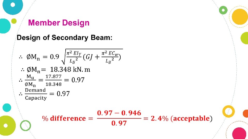
Member Design of Secondary Beam :
connections
Two Rafters Connection (Apex ):
Rafter-Column connection
Sec-Main Beam Connection:
Beam-column Connection:
Beam-Column Connection hand Checks: loads in beam are: 1 -moment 2 -shear
Assumptions: ØUse 8Ø 22 of A 325 bolts. ØUse an (E 80) weld only on all member sides of (8. 00 mm) thickness. ØUse an (12. 00 mm) steel plate of grade A 36.
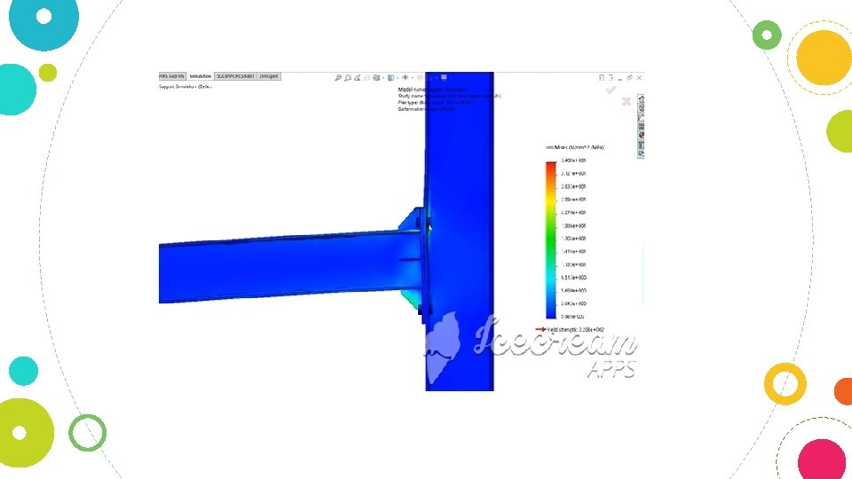
IDEA STATICA Results
Checks For the bolts: first due to moment loads:
Second due to shear loads:
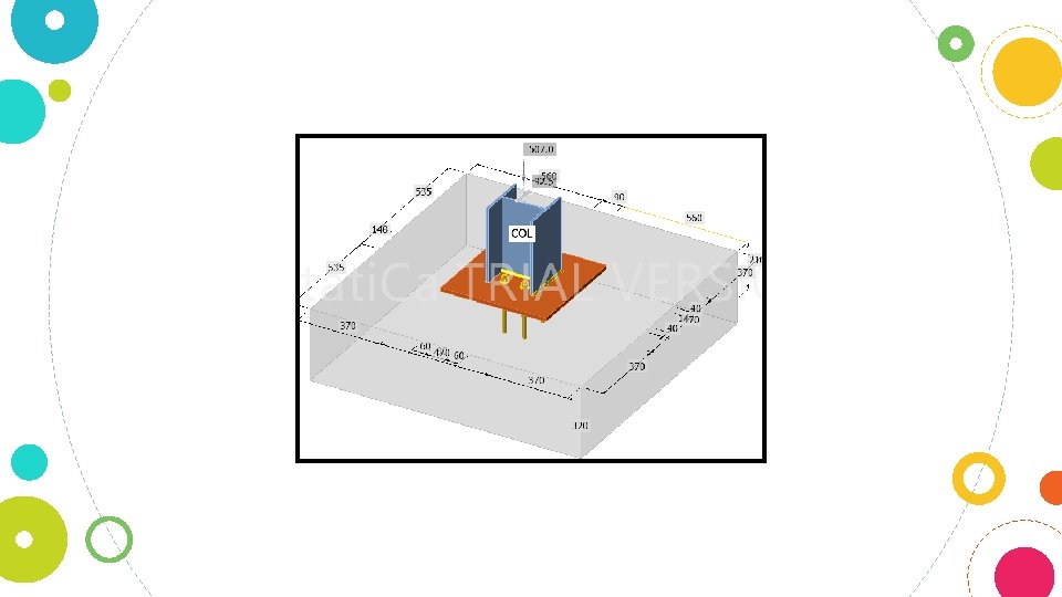
Base plate connection the following assumptions are made for this connection on IDEA Statica Use 4Ø 16 bolts. . Use a (16 mm) steel plate of grade A 36. Use an (E 60) weld only on the flange sides of (8. 00 mm) thickness. Use a vertical bolt spacing of (140. 00 mm). Use a horizontal bolt spacing of (90. 00 mm). Use a vertical distance between the plate edge and the bolt of (165. 00 mm). Use a horizontal distance between the plate edge and the bolt of (190. 00 mm). Use a horizontal distance between the section flange and the bolts of (60. 00 mm). Use plate dimensions of (470. 00 x 470. 00 mm).
Base plate Details
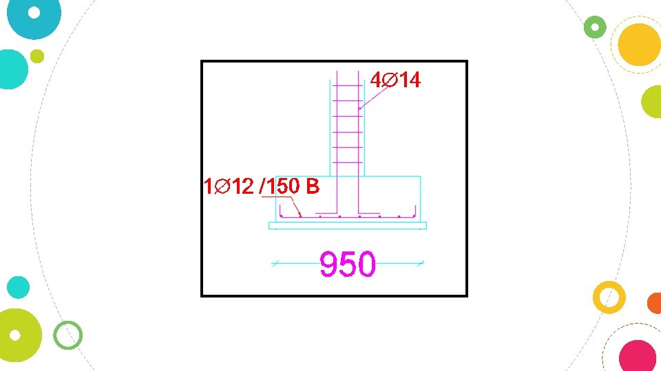
Footing Dimensions
Flexural Design of Footing