ANALYSIS AND DESIGN OF KFC RESTAURANTNABLUS BRANCH Prepared

ANALYSIS AND DESIGN OF KFC RESTAURANTNABLUS BRANCH Prepared by: Maha Horani - Nirmeen Jomaa Supervised by: Dr: Riyad Awad
 ØLoads Ø")
Contents ØProject description and the modified plans ØDesign criteria (Codes and materials) ØLoads Ø 3 -D modeling Ø 3 -D analysis and Design

PROJECT DESCRIPTION AND THE MODIFIED PLANS

Description The project is design of KFC building near Al-Academia street which is 590 m above mean sea level. It’s a building of Four floors basement , ground , first and second floor with height of 3. 25 m for the basement and 4. 25 m for the other floors. .

Original Plans: Basement plan:

Original Plans: First floor plan:

Modified Plan: All the floors will have the following plan with rotating the columns as follows and with adding the following shear walls (the reasons will be discussed later):
")
DESIGN CRITERIA (CODES AND MATERIALS)
. ØJordanian Code")
Design Criteria: Codes: ØAmerican Society of Civil Engineering code (ASCE 7 -10). ØJordanian Code – 2006. ØInternational building code 2012 (IBC 2012). ØAmerican Concrete Institute code (ACI 318 -14).

Design Criteria: Materials: ØConcrete:

Design Criteria: Materials: ØSteel: üReinforced steel: The same steel type will be used for all structural elements which is ASTM A 955 Grade 60, and this type has a tensile strength of 620 MPa and a yield strength of 420 MPa.

Design Criteria: Materials:

LOADS

Gravity Loads: § Live Load: It is a load produced by the use and occupancy of the building, From chapter 4 in ASCE 7 -10 and from Table 1. 2 the live load for residential buildings mainly dining rooms and restaurants = 4. 79 KN/m 2. Also, assuming that one m 2 can contain 4 persons with average weights of 80 Kg, weight for one person=80*10/1000=0. 8 KN, for four persons/m 2=0. 8*4=3. 2 KN/m 2, To be more conservative , the live load will be taken to be 5. 5 KN/m 2.

Gravity Loads: Dead Load and Super imposed dead : SD in the Slab= 5 KN/m 2 SD in the exterior beams=27 KN/m Unit Material Thickness weight(KN/m 3) Tiles 30 mm 26 Mortar 20 mm 23 Filling material 100 mm 18 Plastering 15 mm 23 Masonry wall Masonry stone 50 mm 27 Plain concert 150 mm 23 Blocks 100 mm 12 Plastering 15 mm 23

Gravity Loads: Snow load: it depends on the location and the altitude Ground snow : From the Jordanian code depending on the altitude above mean see level which is 590 m amsl.

Gravity Loads: § Snow load: For Flat roof: § Ce= 1. 1 , Ct=1. 3 , I=1 , Pg=0. 594 § Pf=0. 6 KN/m 2 on the roof

Lateral loads: § Seismic loads: 3 procedures to analyze seismic loads: 1 -Equivalent lateral force analysis (equivalent static) 2 -Modal response spectrum analysis 3 - Seismic response history procedure (time history)

Lateral loads: § Seismic loads: § Site class is D(the allowable bearing capacity is 120 KN/m 2) § Risk category || and importance factor=1 § The design parameters that will be used is the maximum from the mapped values and scientific research values: § For Nablus Z=0. 2 § S 1=1. 25 Z=0. 25 , Ss=2. 5 Z=0. 5 SDS = SMS = 0. 7 and SD 1 = SM 1 = 0. 475

Lateral loads: § Seismic design category D § So, its permitted to use response spectrum and time history only. § Use response spectrum.

Lateral loads: Seismic loads: The structure will be designed as building frame system: § Response modification factor: R=6 § Deflection Amplification Factor (Cd) =5 § System Over Strength Factor (Ω 0)=2. 5 § The response spectrum results should be larger than 80% ELF results.

Lateral loads: § Soil pressure in basement wall:

3 -D MODELING
 1000 mm 350")
3 -D modeling: Preliminary Dimensions: Member Width depth Slab(one way solid) 1000 mm 350 mm 400 mm Beam 1 Beam 2 500 mm 550 mm Beam 3 500 mm 600 mm Beam 4 300 mm 350 mm

3 -D modeling: Preliminary Dimensions: Member Column 1 Column 2 Width depth 500 mm 800 mm 500 mm Shear walls - 200 mm Basement wall - 300 mm ØThe columns are rotated because the load is transferring at the x direction( to have larger moment of inertia in the direction of the load) ØThe shear walls added to prevent torsion in the fundamental mode ØFundamental mode = 0. 661 sec in the y-direction.

3 -D modeling:

3 -D modeling:

3 -D ANALYSIS AND DESIGN
:")
3 -D analysis(checks):
: ɸ 12/90 mm Top bars")
3 -D Design: ØSlab Design: ØMain steel (at x-direction): ɸ 12/90 mm Top bars and ɸ 12/120 mm bottom bars ØShrinkage steel(y-direction): ɸ 12/160 mm top and bottom bars

3 -D Design:

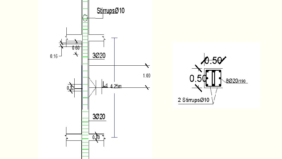
3 -D Design: ØColumns Design: Column 500× 500 for example: P=1%, As=2500 mm 2 Use 8 bars ɸ 20 mm and 2ɸ 10 stirrup /160 mm for length 600 mm from the beam column joint and 2ɸ 10/320 mm for the rest length of the column.

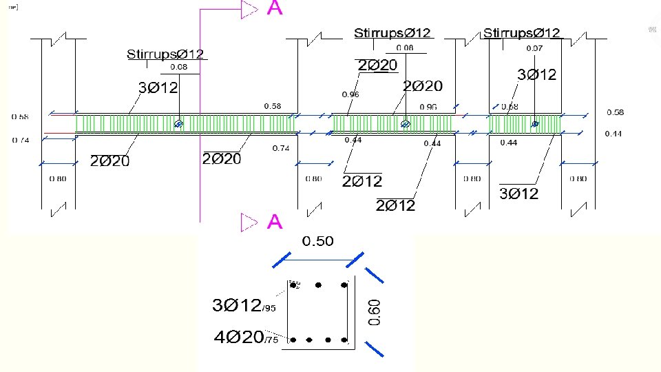
3 -D Design: ØBeams Design: For beams have section 500× 600 mm as an example Pu=0. 1 Ag F’c=840 KN> Axial at all beams , so design it as beams

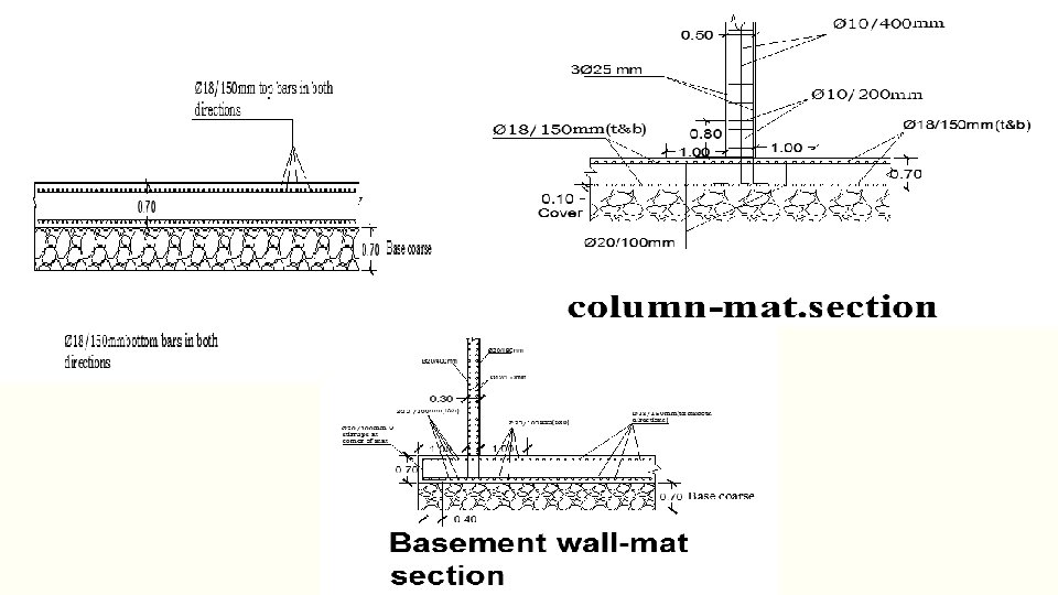
Footing Design: ØThe footing is mat foundation with thickness of 70 cm. ØUse 70 cm base coarse to increase the bearing capacity of soil ØPunching is checked for this thickness and its ok ØArea of the mat = area of the building +1 m 2 from all around the building

- Slides: 38