
An Introduction to Networking Chapter 1 Part I
- Slides: 55
An Introduction to Networking Chapter 1
Part I: Basic Networks Concepts we will see throughout the book
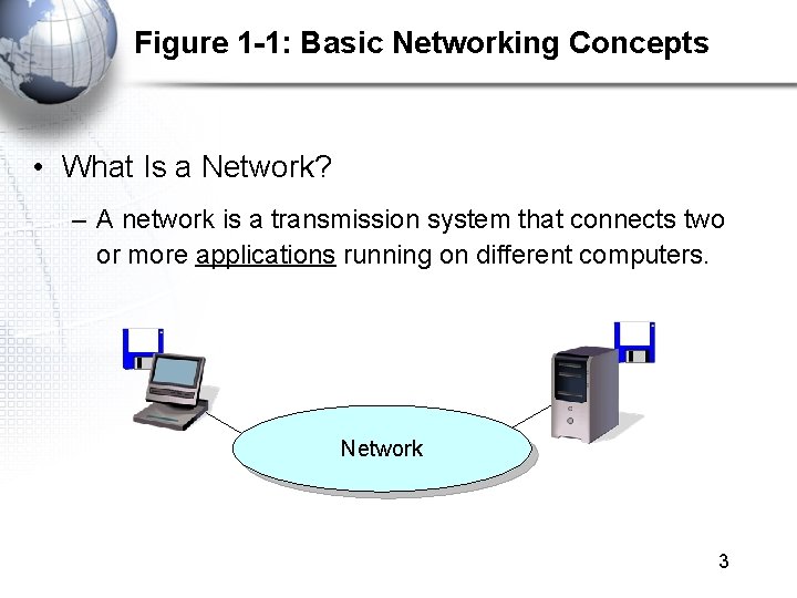
Figure 1 -1: Basic Networking Concepts • What Is a Network? – A network is a transmission system that connects two or more applications running on different computers. Network 3
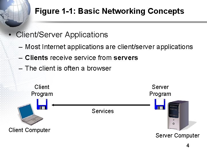
Figure 1 -1: Basic Networking Concepts • Client/Server Applications – Most Internet applications are client/server applications – Clients receive service from servers – The client is often a browser Client Program Server Program Services Client Computer Server Computer 4
Part II: The Nine Elements of a Network Although the idea of “network” is simple, you must understand the nine elements found in most networks
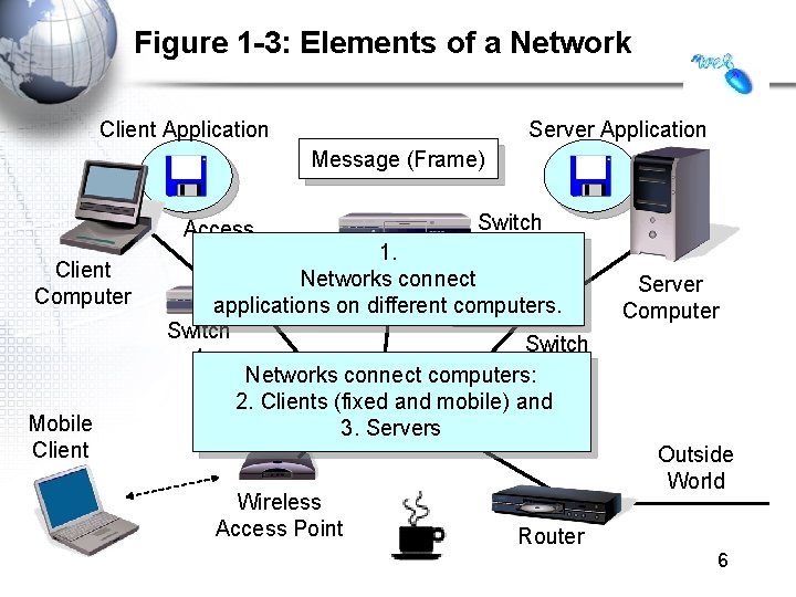
Figure 1 -3: Elements of a Network Client Application Server Application Message (Frame) Client Computer Mobile Client Access Line Switch 2 1. Networks connect applications on different computers. Switch 1 Trunk Networks connect computers: 3 2. Line Clients (fixed and mobile) and 3. Servers Wireless Access Point Server Computer Outside World Router 6
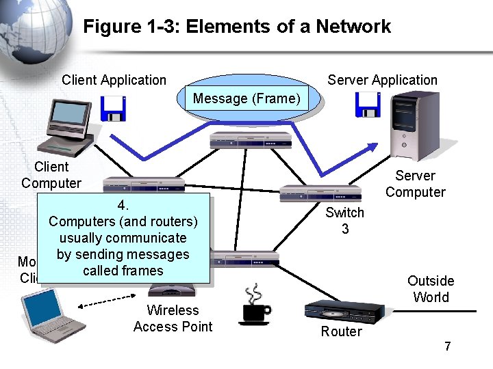
Figure 1 -3: Elements of a Network Client Application Server Application Message (Frame) Client Computer Switch 4. 1 Computers (and routers) Trunk usually communicate Line by sending messages Mobile called frames Client Wireless Access Point Server Computer Switch 3 Outside World Router 7
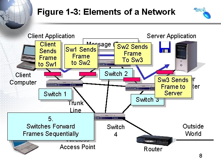
Figure 1 -3: Elements of a Network Client Application Server Application Message (Frame) Client Sw 2 Sends Sw 1 Sends Frame To Sw 3 to Sw 2 to Sw 1 Switch 2 Client Computer Switch 1 Trunk Line Mobile 5. Client Switches Forward Frames Sequentially Wireless Access Point Server Sw 3 Sends Computer Frame to Server Switch 3 Outside World Switch 4 Router 8
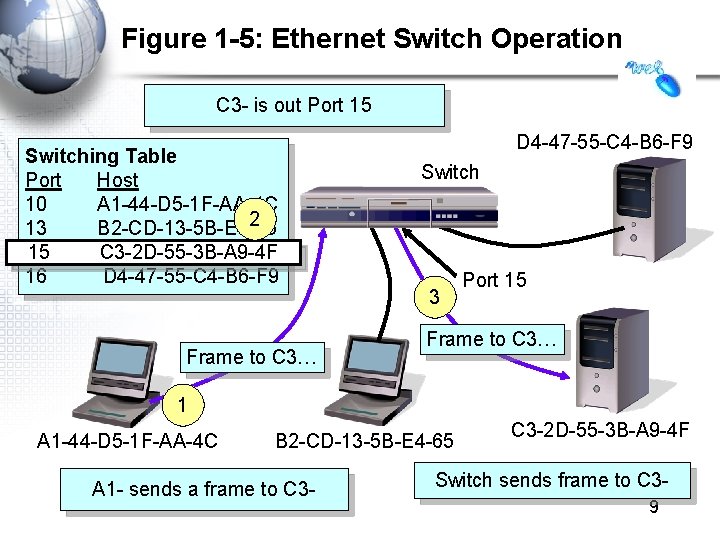
Figure 1 -5: Ethernet Switch Operation C 3 - is out Port 15 Switching Table Port Host 10 A 1 -44 -D 5 -1 F-AA-4 C 2 13 B 2 -CD-13 -5 B-E 4 -65 15 C 3 -2 D-55 -3 B-A 9 -4 F 16 D 4 -47 -55 -C 4 -B 6 -F 9 Frame to C 3… D 4 -47 -55 -C 4 -B 6 -F 9 Switch 3 Port 15 Frame to C 3… 1 A 1 -44 -D 5 -1 F-AA-4 C B 2 -CD-13 -5 B-E 4 -65 A 1 - sends a frame to C 3 -2 D-55 -3 B-A 9 -4 F Switch sends frame to C 39
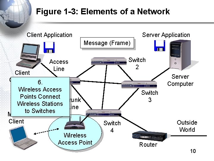
Figure 1 -3: Elements of a Network Client Application Server Application Message (Frame) Switch 2 Access Line Client Computer 6. Switch Wireless Access 1 Points Connect Trunk Wireless Stations Line to Switches Mobile Client Wireless Access Point Server Computer Switch 3 Outside World Switch 4 Router 10
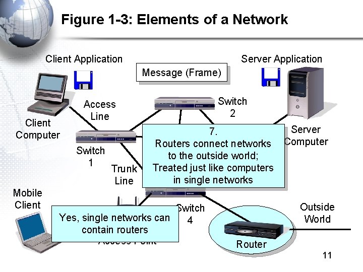
Figure 1 -3: Elements of a Network Client Application Server Application Message (Frame) Client Computer Switch 1 Mobile Client Switch 2 Access Line Trunk Line Server 7. Routers connect networks Computer to the outside world; Switch Treated just like computers 3 in single networks Switch Yes, single networks can 4 Wireless contain routers Access Point Outside World Router 11
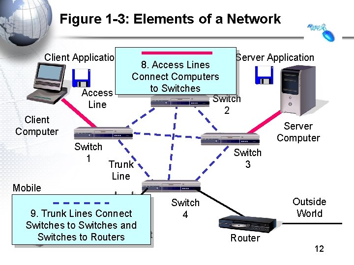
Figure 1 -3: Elements of a Network Client Application Access Line Client Computer Switch 1 Server Application 8. Access Lines Message (Frame) Connect Computers to Switches Switch 2 Server Computer Switch 3 Trunk Line Mobile Client 9. Trunk Lines Connect Wireless Switches to Switches and Access Point Switches to Routers Outside World Switch 4 Router 12
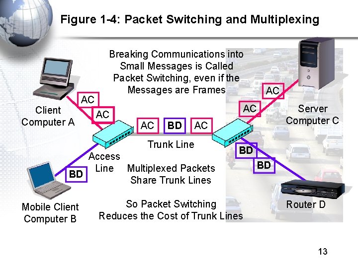
Figure 1 -4: Packet Switching and Multiplexing Client Computer A AC Breaking Communications into Small Messages is Called Packet Switching, even if the Messages are Frames AC AC AC BD AC Trunk Line Access Line Multiplexed Packets BD Share Trunk Lines Mobile Client Computer B AC Server Computer C BD So Packet Switching Reduces the Cost of Trunk Lines BD Router D 13
Part III: Transmission Speed
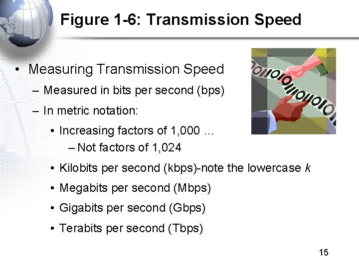
Figure 1 -6: Transmission Speed • Measuring Transmission Speed – Measured in bits per second (bps) – In metric notation: • Increasing factors of 1, 000 … – Not factors of 1, 024 • Kilobits per second (kbps)-note the lowercase k • Megabits per second (Mbps) • Gigabits per second (Gbps) • Terabits per second (Tbps) 15
Figure 1 -6: Transmission Speed • Measuring Transmission Speed – What is 23, 000 bps in metric notation? – What is 3, 000, 000 in metric notation? – What is 15, 100, 000 bps in metric notation? • Occasionally measured in bytes per second • If so, written as Bps • Usually seen in file download speeds 16
Figure 1 -6: Transmission Speed • Writing Transmission Speeds in Proper Form – The rule for writing speeds (and metric numbers in general) in proper form is that there should be 1 to 3 places before the decimal point – 23. 72 Mbps is correct (2 places before the decimal point). – 2, 300 Mbps has four places before the decimal point, so it should be rewritten as 2. 3 Gbps (1 place). – 0. 5 Mbps has zero places to the left of the decimal point. It should be written as 500 kbps (3 places). 17
Figure 1 -6: Transmission Speed • Writing Transmission Speeds in Proper Form – How to convert 1, 200 Mbps to proper form • Divide the number 1, 200 by 1000 – Move decimal point three places to the left: 1. 200 • Multiply the metric suffix Mbps by 1, 000 – Gbps • Result: – 1. 2 Gbps 18
Figure 1 -6: Transmission Speed • Writing Transmission Speeds in Proper Form – How to convert 0. 036 Mbps to proper form • Multiply the number 0. 036 by 1000 – Move decimal point three places to the right: 36 • Divide the metric suffix Mbps by 1, 000 – kbps • Result: – 36 kbps 19
Figure 1 -6: Transmission Speed • Writing Transmission Speeds in Proper Form – How should you write the following in proper form? • 549. 73 kbps • 0. 47 Gbps • 11, 200 Mbps • . 0021 Gbps 20
Figure 1 -6: Transmission Speed • Rated Speed – The speed in bits per second that you should get (advertised or specified in the standard). • Throughput – The speed you actually get – Almost always lower than the rated speed • On Shared Transmission Lines – Aggregate throughput—total throughput for all users – Individual throughput—what individual users get 21
Part IV: LANs and WANs
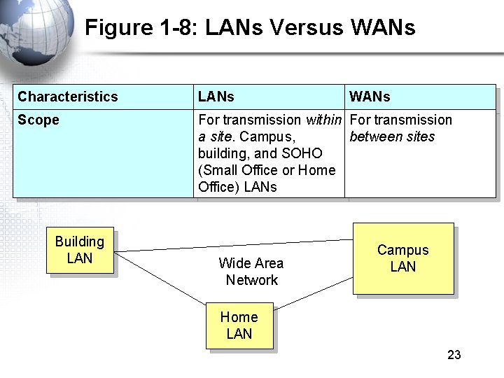
Figure 1 -8: LANs Versus WANs Characteristics LANs Scope For transmission within For transmission a site. Campus, between sites building, and SOHO (Small Office or Home Office) LANs Building LAN Wide Area Network WANs Campus LAN Home LAN 23
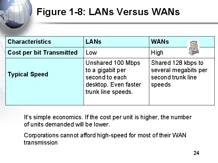
Figure 1 -8: LANs Versus WANs Characteristics LANs WANs Cost per bit Transmitted Low High Typical Speed Unshared 100 Mbps to a gigabit per second to each desktop. Even faster trunk line speeds. Shared 128 kbps to several megabits per second trunk line speeds It’s simple economics. If the cost per unit is higher, the number of units demanded will be lower. Corporations cannot afford high-speed for most of their WAN transmission 24
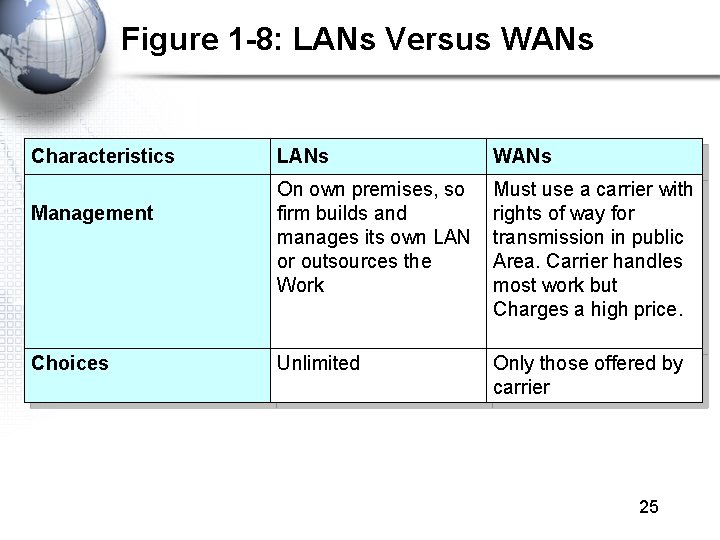
Figure 1 -8: LANs Versus WANs Characteristics Management Choices LANs WANs On own premises, so firm builds and manages its own LAN or outsources the Work Must use a carrier with rights of way for transmission in public Area. Carrier handles most work but Charges a high price. Unlimited Only those offered by carrier 25
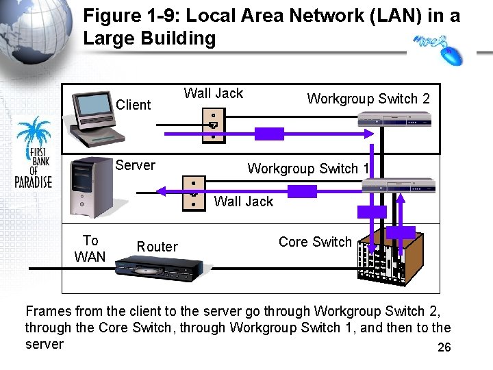
Figure 1 -9: Local Area Network (LAN) in a Large Building Client Server Wall Jack Workgroup Switch 2 Workgroup Switch 1 Wall Jack To WAN Router Core Switch Frames from the client to the server go through Workgroup Switch 2, through the Core Switch, through Workgroup Switch 1, and then to the server 26
Part V: Internets
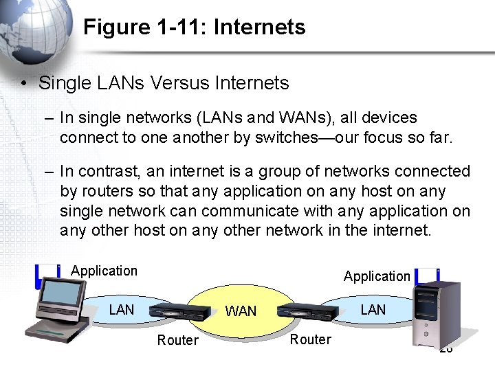
Figure 1 -11: Internets • Single LANs Versus Internets – In single networks (LANs and WANs), all devices connect to one another by switches—our focus so far. – In contrast, an internet is a group of networks connected by routers so that any application on any host on any single network can communicate with any application on any other host on any other network in the internet. Application LAN WAN Router 28
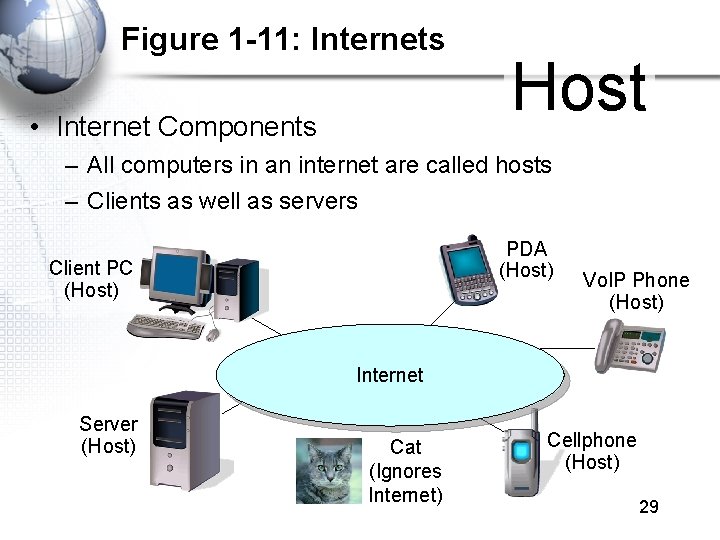
Figure 1 -11: Internets • Internet Components Host – All computers in an internet are called hosts – Clients as well as servers PDA (Host) Client PC (Host) Vo. IP Phone (Host) Internet Server (Host) Cat (Ignores Internet) Cellphone (Host) 29
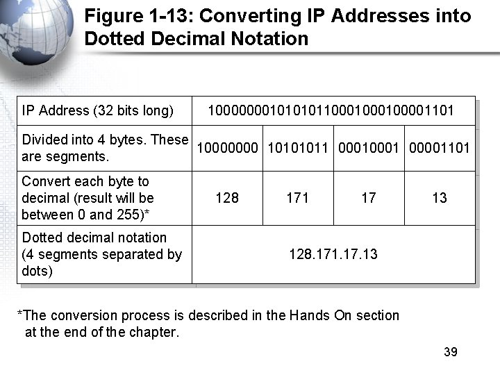
Figure 1 -11: Internets • Hosts Have Two Addresses • IP Address – This is the host’s official address on its internet – 32 bits long – Expressed for people in dotted decimal notation (e. g. , 128. 171. 17. 13) • Single-Network Addresses – This is the host’s address on its single network – Ethernet addresses, for instance, are 48 bits long – Expressed in hexadecimal notation (e. g. , AF-23 -9 B-E 8 -67 -47) 30
Figure 1 -11: Internets • Networks are connected by devices called routers – Switches provide connections within networks, while routers provide connections between networks in an internet. • Frames and Packets – In single networks, message are called frames – In internets, messages are called packets 31
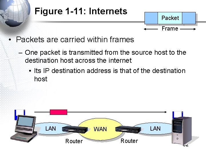
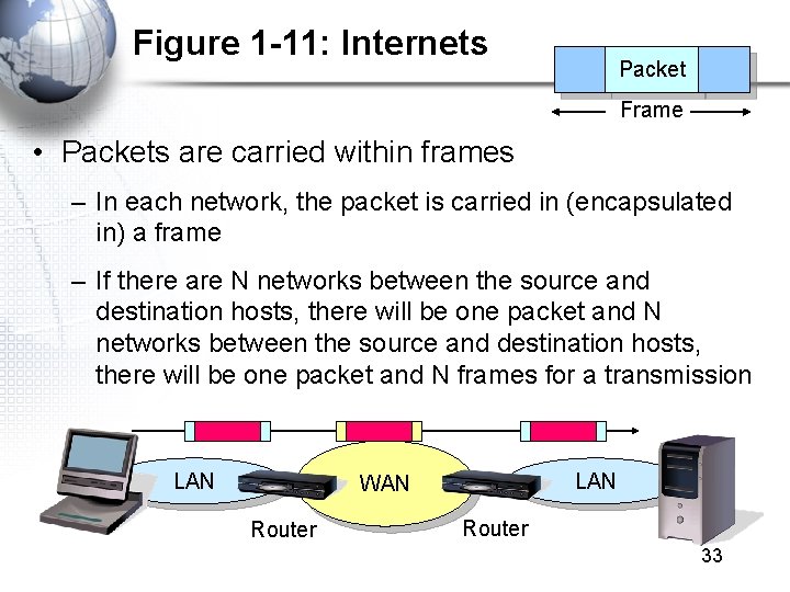
Figure 1 -11: Internets Packet Frame • Packets are carried within frames – One packet is transmitted from the source host to the destination host across the internet • Its IP destination address is that of the destination host LAN WAN Router 32
Figure 1 -11: Internets Packet Frame • Packets are carried within frames – In each network, the packet is carried in (encapsulated in) a frame – If there are N networks between the source and destination hosts, there will be one packet and N frames for a transmission LAN WAN Router 33
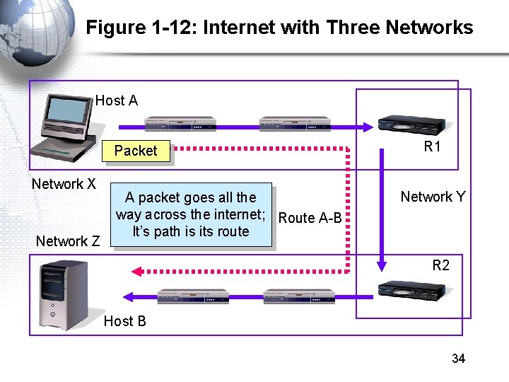
Figure 1 -12: Internet with Three Networks Host A Packet Network X Network Z A packet goes all the way across the internet; Route A-B It’s path is its route R 1 Network Y R 2 Host B 34
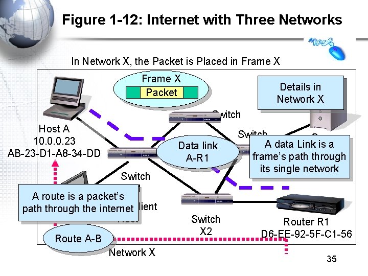
Figure 1 -12: Internet with Three Networks In Network X, the Packet is Placed in Frame X Packet Details in Network X Switch Host A 10. 0. 0. 23 AB-23 -D 1 -A 8 -34 -DD Data link A-R 1 Switch X 1 A route is a packet’s path through the Mobile internet. Client Host Route A-B Network X Switch X 2 Switch Server A data Link is a Host frame’s path through its single network Router R 1 D 6 -EE-92 -5 F-C 1 -56 35
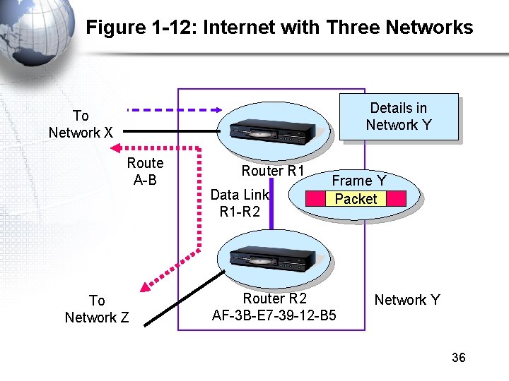
Figure 1 -12: Internet with Three Networks Details in Network Y To Network X Route A-B To Network Z Router R 1 Data Link R 1 -R 2 Frame Y Packet Router R 2 AF-3 B-E 7 -39 -12 -B 5 Network Y 36
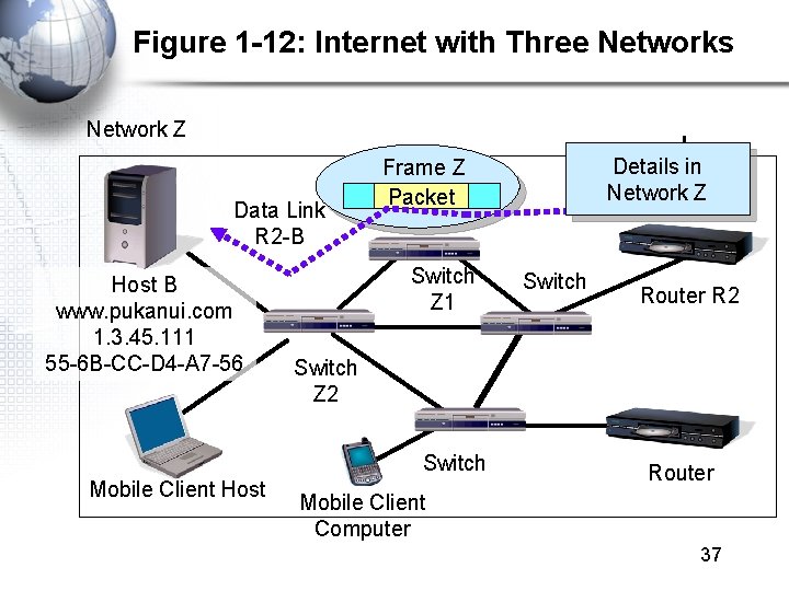
Figure 1 -12: Internet with Three Networks Network Z Data Link R 2 -B Host B www. pukanui. com 1. 3. 45. 111 55 -6 B-CC-D 4 -A 7 -56 Switch Z 1 Switch Router R 2 Switch Z 2 Switch Mobile Client Host Details in Network Z Frame Z Packet Router Mobile Client Computer 37
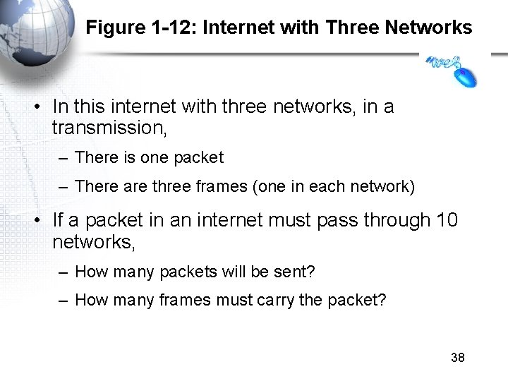
Figure 1 -12: Internet with Three Networks • In this internet with three networks, in a transmission, – There is one packet – There are three frames (one in each network) • If a packet in an internet must pass through 10 networks, – How many packets will be sent? – How many frames must carry the packet? 38
Figure 1 -13: Converting IP Addresses into Dotted Decimal Notation IP Address (32 bits long) 100000001011000100001101 Divided into 4 bytes. These 10000000 10101011 0001 00001101 are segments. Convert each byte to decimal (result will be between 0 and 255)* Dotted decimal notation (4 segments separated by dots) 128 171 17 13 128. 171. 17. 13 *The conversion process is described in the Hands On section at the end of the chapter. 39
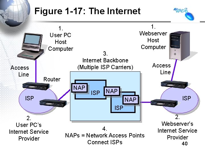
Figure 1 -17: The Internet 1. User PC Host Computer Access Line 1. Webserver Host Computer 3. Internet Backbone (Multiple ISP Carriers) Access Line Router NAP ISP 2. User PC’s Internet Service Provider 4. NAPs = Network Access Points Connect ISPs 2. Webserver’s Internet Service Provider 40
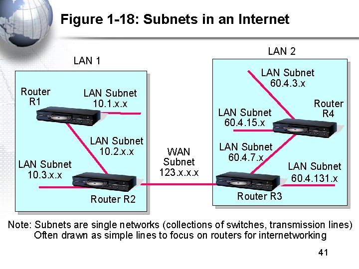
Figure 1 -18: Subnets in an Internet LAN 2 LAN 1 Router R 1 LAN Subnet 60. 4. 3. x LAN Subnet 10. 1. x. x LAN Subnet 10. 2. x. x LAN Subnet 10. 3. x. x Router R 2 LAN Subnet 60. 4. 15. x WAN Subnet 123. x. x. x LAN Subnet 60. 4. 7. x Router R 4 LAN Subnet 60. 4. 131. x Router R 3 Note: Subnets are single networks (collections of switches, transmission lines) Often drawn as simple lines to focus on routers for internetworking 41
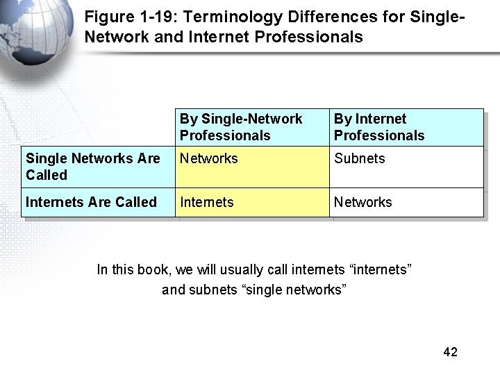
Figure 1 -19: Terminology Differences for Single. Network and Internet Professionals By Single-Network Professionals By Internet Professionals Single Networks Are Called Networks Subnets Internets Are Called Internets Networks In this book, we will usually call internets “internets” and subnets “single networks” 42
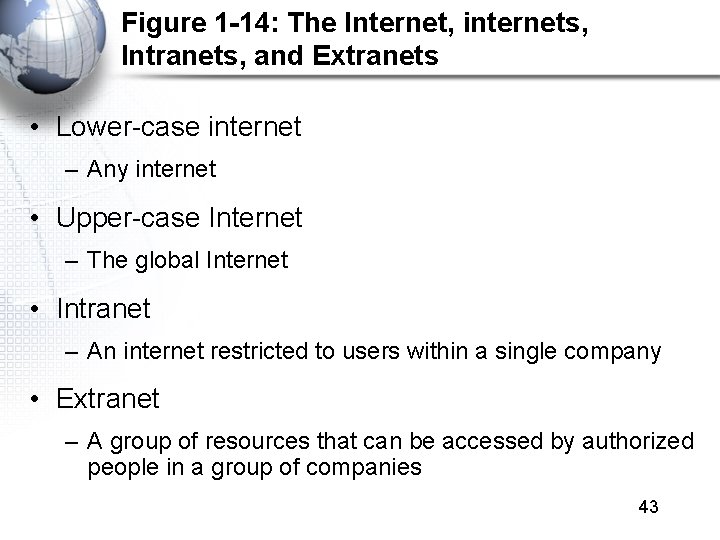
Figure 1 -14: The Internet, internets, Intranets, and Extranets • Lower-case internet – Any internet • Upper-case Internet – The global Internet • Intranet – An internet restricted to users within a single company • Extranet – A group of resources that can be accessed by authorized people in a group of companies 43
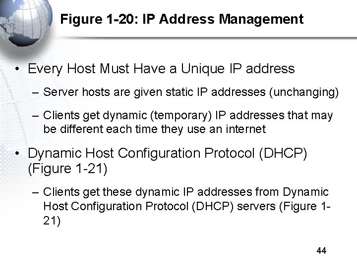
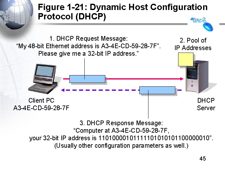
Figure 1 -20: IP Address Management • Every Host Must Have a Unique IP address – Server hosts are given static IP addresses (unchanging) – Clients get dynamic (temporary) IP addresses that may be different each time they use an internet • Dynamic Host Configuration Protocol (DHCP) (Figure 1 -21) – Clients get these dynamic IP addresses from Dynamic Host Configuration Protocol (DHCP) servers (Figure 121) 44
Figure 1 -21: Dynamic Host Configuration Protocol (DHCP) 1. DHCP Request Message: “My 48 -bit Ethernet address is A 3 -4 E-CD-59 -28 -7 F”. Please give me a 32 -bit IP address. ” Client PC A 3 -4 E-CD-59 -28 -7 F 2. Pool of IP Addresses DHCP Server 3. DHCP Response Message: “Computer at A 3 -4 E-CD-59 -28 -7 F, your 32 -bit IP address is 1101000010111110101100000010”. (Usually other configuration parameters as well. ) 45
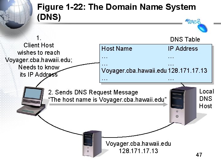
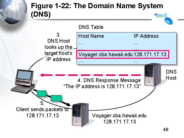
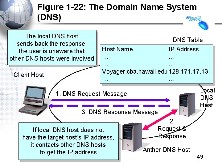
Figure 1 -20: IP Address Management • Domain Name System (DNS) (Figure 1 -22) – IP addresses are official addresses on the Internet and other internets – Hosts can also have host names (e. g. , cnn. com) • Not official—like nicknames – If you only know the host name of a host that you want to reach, your computer must learn its IP address • DNS servers tell our computer the IP address of a target host whose name you know. (Figure 1 -22) 46
Figure 1 -22: The Domain Name System (DNS) 1. Client Host wishes to reach Voyager. cba. hawaii. edu; Needs to know its IP Address DNS Table Host Name IP Address … … Voyager. cba. hawaii. edu 128. 171. 17. 13 … … 2. Sends DNS Request Message “The host name is Voyager. cba. hawaii. edu” Voyager. cba. hawaii. edu 128. 171. 17. 13 Local DNS Host 47
Figure 1 -22: The Domain Name System (DNS) DNS Table 3. DNS Host looks up the target host’s IP address Host Name IP Address … … Voyager. cba. hawaii. edu 128. 171. 17. 13 … … 4. DNS Response Message “The IP address is 128. 171. 17. 13” 5. Client sends packets to 128. 171. 17. 13 DNS Host Voyager. cba. hawaii. edu 128. 171. 17. 13 48
Figure 1 -22: The Domain Name System (DNS) The local DNS host sends back the response; the user is unaware that other DNS hosts were involved Client Host DNS Table Host Name IP Address … … Voyager. cba. hawaii. edu 128. 171. 17. 13 … … 1. DNS Request Message 3. DNS Response Message If local DNS host does not have the target host’s IP address, it contacts other DNS hosts to get the IP address Local DNS Host 2. Request & Response Anther DNS Host 49
Part VI: Security
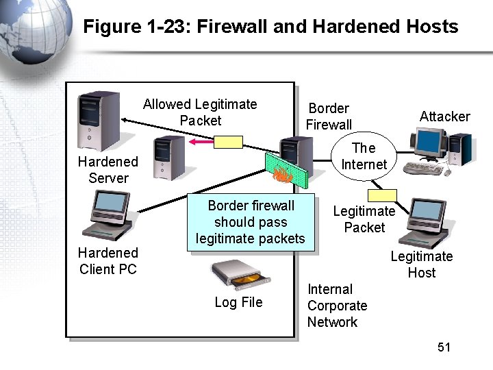
Figure 1 -23: Firewall and Hardened Hosts Allowed Legitimate Packet Border Firewall The Internet Hardened Server Hardened Client PC Attacker Border firewall should pass legitimate packets Legitimate Packet Legitimate Host Log File Internal Corporate Network 51
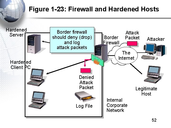
Figure 1 -23: Firewall and Hardened Hosts Hardened Server Border firewall should deny (drop) and log attack packets Border Firewall Attack Packet Attacker The Internet Hardened Client PC Denied Attack Packet Log File Legitimate Host Internal Corporate Network 52
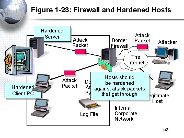
Figure 1 -23: Firewall and Hardened Hosts Hardened Server Attack Packet Border Firewall Attack Packet Attacker The Internet Hardened Client PC Attack Packet Hosts should Denied be hardened Attack against attack packets Packet that get through Legitimate Host Internal Corporate Log File Network 53
Figure 1 -24: Cryptographic Protections • Cryptography – The use of mathematical operations to thwart attacks on message dialogues between pairs of communicating parties (people, programs, or devices) • Initial Authentication – Determine the other party’s identity to thwart impostors 54
Figure 1 -24: Cryptographic Protections • Message-by-Message Protections – Encryption to provide confidentiality so that an eavesdropper cannot reach intercepted messages – Electronic signatures provide message-by-message authentication to prevent the insertion of messages by an impostor after initial authentication – Electronic signatures usually also provide message integrity; this tells the receiver whether anyone has changed the message en route 55