
An IFU for IFOSC on IUCAA 2 m







- Slides: 37
An IFU for IFOSC on IUCAA 2 m Telescope A. N. Ramaprakash Inter-University Centre for Astronomy & Astrophysics, Pune Abhay, Atul, Hillol, Kalpesh, Mahesh, Moin, Mudit, Pravin, Ranjan, Shyam, Sujith, Swapnil, Vilas 4. 12. 2007 A. N. Ramaprakash, IUCAA
üIFU on IUCAA 2 m Telescope üDesign and Performance of the IFU • • • Telescope and IFOSC parameters Basic structure of the system Constraints on IFU Design for IFOSC on IUCAA Telescope • • • Basic Design Selection criteria for parameters Performance üIFOSC performance with IFU / Summary 4. 12. 2007 A. N. Ramaprakash, IUCAA 2 IRSIS Meeting, TIFR, Mumbai Plan of the Talk
IRSIS Meeting, TIFR, Mumbai Techniques for 2 -D Spectroscopy http: //www. cfai. dur. ac. uk/new/spectroscopy. html 4. 12. 2007 A. N. Ramaprakash, IUCAA 3
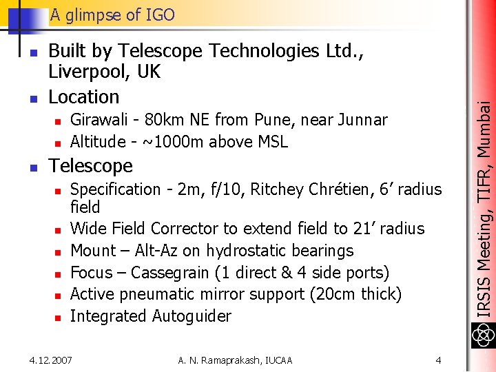
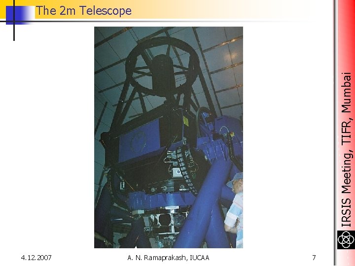
n n Built by Telescope Technologies Ltd. , Liverpool, UK Location n Girawali - 80 km NE from Pune, near Junnar Altitude - ~1000 m above MSL Telescope n n n Specification - 2 m, f/10, Ritchey Chrétien, 6’ radius field Wide Field Corrector to extend field to 21’ radius Mount – Alt-Az on hydrostatic bearings Focus – Cassegrain (1 direct & 4 side ports) Active pneumatic mirror support (20 cm thick) Integrated Autoguider 4. 12. 2007 A. N. Ramaprakash, IUCAA 4 IRSIS Meeting, TIFR, Mumbai A glimpse of IGO
IRSIS Meeting, TIFR, Mumbai Observatory Views 4. 12. 2007 A. N. Ramaprakash, IUCAA 5
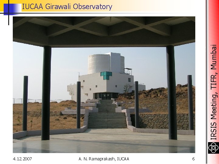
IRSIS Meeting, TIFR, Mumbai IUCAA Girawali Observatory 4. 12. 2007 A. N. Ramaprakash, IUCAA 6
IRSIS Meeting, TIFR, Mumbai The 2 m Telescope 4. 12. 2007 A. N. Ramaprakash, IUCAA 7
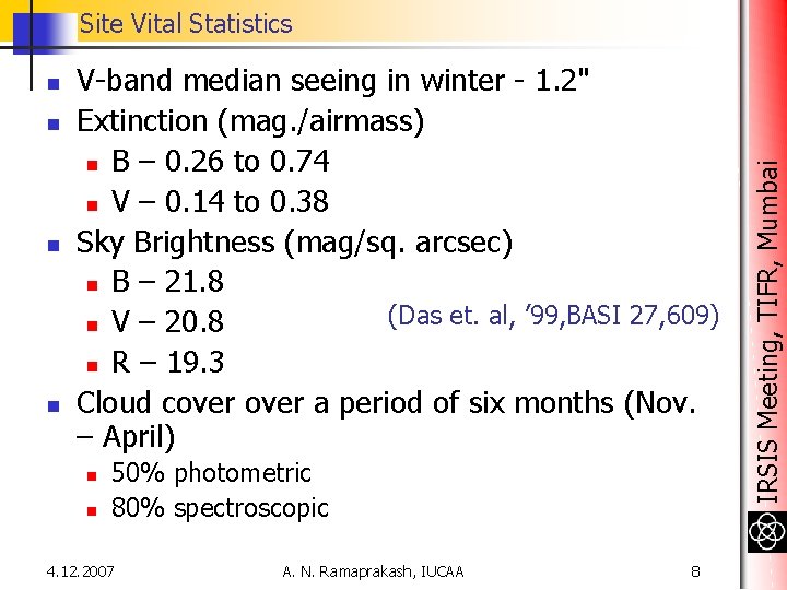
n n V-band median seeing in winter - 1. 2" Extinction (mag. /airmass) n B – 0. 26 to 0. 74 n V – 0. 14 to 0. 38 Sky Brightness (mag/sq. arcsec) n B – 21. 8 (Das et. al, ’ 99, BASI 27, 609) n V – 20. 8 n R – 19. 3 Cloud cover a period of six months (Nov. – April) n n 50% photometric 80% spectroscopic 4. 12. 2007 A. N. Ramaprakash, IUCAA 8 IRSIS Meeting, TIFR, Mumbai Site Vital Statistics
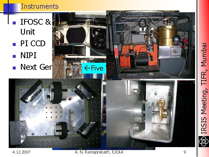
Instruments n n n IFOSC & Calibration Unit PI CCD NIPI Next Generation Five Year Plan 4. 12. 2007 A. N. Ramaprakash, IUCAA IRSIS Meeting, TIFR, Mumbai n 9
n n n n UBVRI filters 0. 8”, 1. 5”, 2” x 11’ slits 10 grisms (2 echelle & 2 cross dispersers) R = 190 to R = 3700 = 0. 35 m to = 0. 85 m Polarimetry mode 2 K x 2 K EEV CCD with 13. 5 m 2 pixels 40 m/arcsec plate scale on CCD at f/4. 5 (demagnification of 2. 2) 4. 12. 2007 A. N. Ramaprakash, IUCAA 10 IRSIS Meeting, TIFR, Mumbai IUCAA Faint Object Spectrograph Camera (IFOSC)
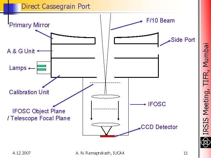
Direct Cassegrain Port Primary Mirror Side Port A & G Unit Lamps Calibration Unit IFOSC Object Plane / Telescope Focal Plane CCD Detector 4. 12. 2007 A. N. Ramaprakash, IUCAA 11 IRSIS Meeting, TIFR, Mumbai F/10 Beam
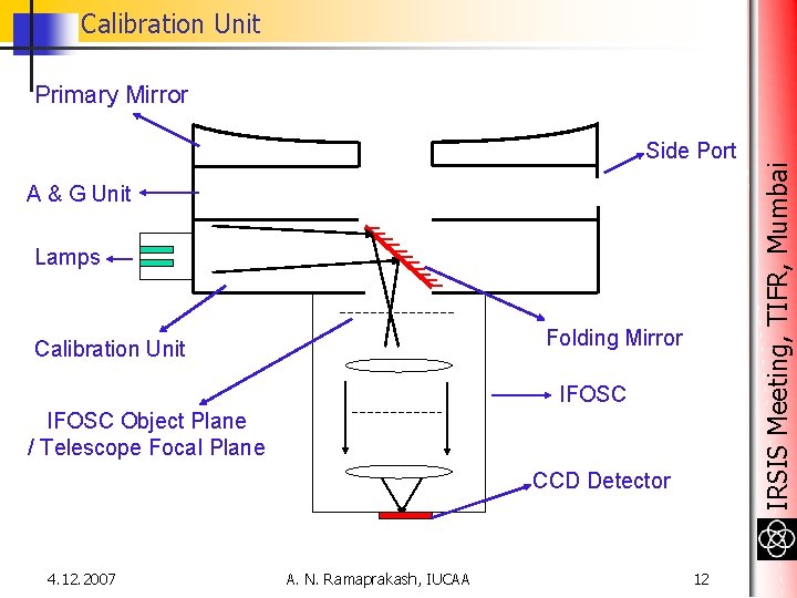
Calibration Unit Side Port A & G Unit Lamps Folding Mirror Calibration Unit IFOSC Object Plane / Telescope Focal Plane CCD Detector 4. 12. 2007 A. N. Ramaprakash, IUCAA 12 IRSIS Meeting, TIFR, Mumbai Primary Mirror
Cassegrain Side Port Primary Mirror Folding Mirror IRSIS Meeting, TIFR, Mumbai Side Port Instrument A & G Unit Lamps Calibration Unit IFOSC Object Plane / Telescope Focal Plane CCD Detector 4. 12. 2007 A. N. Ramaprakash, IUCAA 13
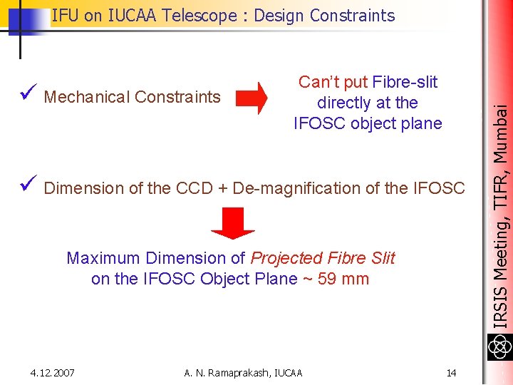
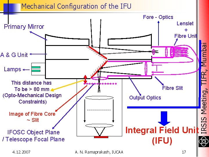
ü Mechanical Constraints Can’t put Fibre-slit directly at the IFOSC object plane ü Dimension of the CCD + De-magnification of the IFOSC Maximum Dimension of Projected Fibre Slit on the IFOSC Object Plane ~ 59 mm 4. 12. 2007 A. N. Ramaprakash, IUCAA 14 IRSIS Meeting, TIFR, Mumbai IFU on IUCAA Telescope : Design Constraints
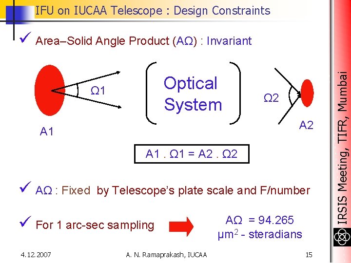
IFU on IUCAA Telescope : Design Constraints Optical System Ω 1 Ω 2 A 1 A 1. Ω 1 = A 2. Ω 2 ü AΩ : Fixed by Telescope’s plate scale and F/number ü For 1 arc-sec sampling 4. 12. 2007 A. N. Ramaprakash, IUCAA AΩ = 94. 265 μm 2 - steradians 15 IRSIS Meeting, TIFR, Mumbai ü Area–Solid Angle Product (AΩ) : Invariant
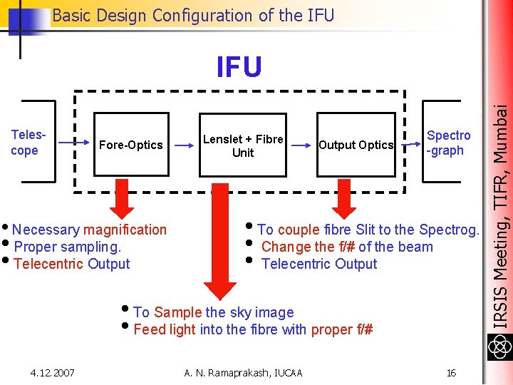
Basic Design Configuration of the IFU Telescope Fore-Optics • Necessary magnification • Proper sampling. • Telecentric Output Lenslet + Fibre Unit Output Optics Spectro -graph • To couple fibre Slit to the Spectrog. • Change the f/# of the beam • Telecentric Output • To Sample the sky image • Feed light into the fibre with proper f/# 4. 12. 2007 A. N. Ramaprakash, IUCAA 16 IRSIS Meeting, TIFR, Mumbai IFU
Mechanical Configuration of the IFU Fore - Optics A & G Unit Lamps This distance has To be > 80 mm (Opto-Mechanical Design Constraints) Fibre Slit Output Optics Image of Fibre Core ~ Slit Integral Field Unit (IFU) IFOSC Object Plane / Telescope Focal Plane 4. 12. 2007 A. N. Ramaprakash, IUCAA 17 IRSIS Meeting, TIFR, Mumbai Lenslet + Fibre Unit Primary Mirror
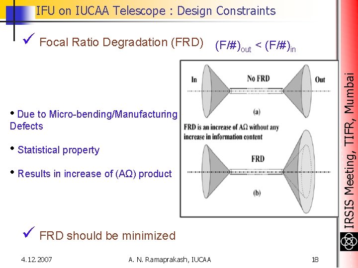
IFU on IUCAA Telescope : Design Constraints (F/#)out < (F/#)in IRSIS Meeting, TIFR, Mumbai ü Focal Ratio Degradation (FRD) • Due to Micro-bending/Manufacturing Defects • Statistical property • Results in increase of (AΩ) product ü FRD should be minimized 4. 12. 2007 A. N. Ramaprakash, IUCAA 18
IRSIS Meeting, TIFR, Mumbai Focal Ration Degradation (Carrasco & Parry, 1994, MNRAS, 271, 1 -12) 4. 12. 2007 A. N. Ramaprakash, IUCAA 19
Design Optimization of the IFU < 5 so that, (F / #) out ~ (F / #)in ü Further, invariance of AΩ Lower the (F/#)fibre Smaller the Fiber Core Diameter Better Spectral Resolution Smaller (F/#)fibre is desirable 4. 12. 2007 A. N. Ramaprakash, IUCAA 20 IRSIS Meeting, TIFR, Mumbai ü To minimize FRD : (F / #)in
Design Optimization of the IFU ü IFOSC accepts ‘F/10’ beam F/# Output Optics F/10 IFOSC Fibre Core Magnification = 10 / (F/#) = M ü The projected slit width = M X Fibre Core Diameter ‘M’ affects the Spectral resolution 4. 12. 2007 A. N. Ramaprakash, IUCAA 21 IRSIS Meeting, TIFR, Mumbai BUT
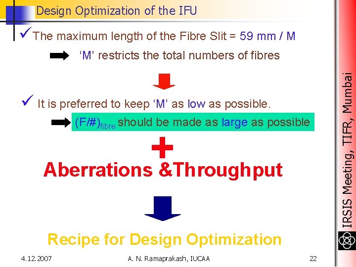
Design Optimization of the IFU üThe maximum length of the Fibre Slit = 59 mm / M ü It is preferred to keep ‘M’ as low as possible. (F/#)fibre should be made as large as possible + Aberrations &Throughput Recipe for Design Optimization 4. 12. 2007 A. N. Ramaprakash, IUCAA 22 IRSIS Meeting, TIFR, Mumbai ‘M’ restricts the total numbers of fibres
Basic scientific constraints of the IFU ü The sky area would be sampled by 100 Lenslets + Fibres ü Three spatial sampling scales 1. 0" per fibre, 0. 8" per fibre and 1. 2" per fibre are being used. ü The sky area sampled by IFU ~ 14 arc-sec X 7 arc-sec (For the case of 1 arc-sec per fibre) 4. 12. 2007 A. N. Ramaprakash, IUCAA 23 IRSIS Meeting, TIFR, Mumbai ü Optimized for the wavelength range 4500 – 8500 Å
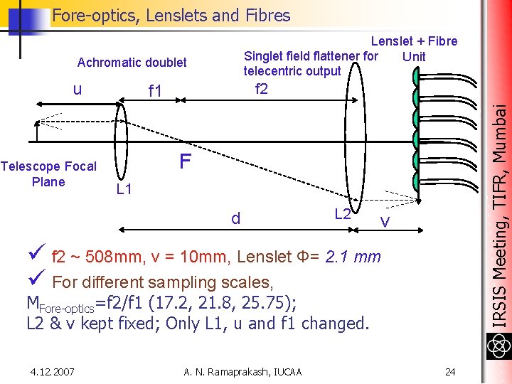
Fore-optics, Lenslets and Fibres Lenslet + Fibre Singlet field flattener for Unit telecentric output Achromatic doublet Telescope Focal Plane f 2 f 1 IRSIS Meeting, TIFR, Mumbai u F L 1 d L 2 v ü f 2 ~ 508 mm, v = 10 mm, Lenslet Φ= 2. 1 mm ü For different sampling scales, MFore-optics=f 2/f 1 (17. 2, 21. 8, 25. 75); L 2 & v kept fixed; Only L 1, u and f 1 changed. 4. 12. 2007 A. N. Ramaprakash, IUCAA 24
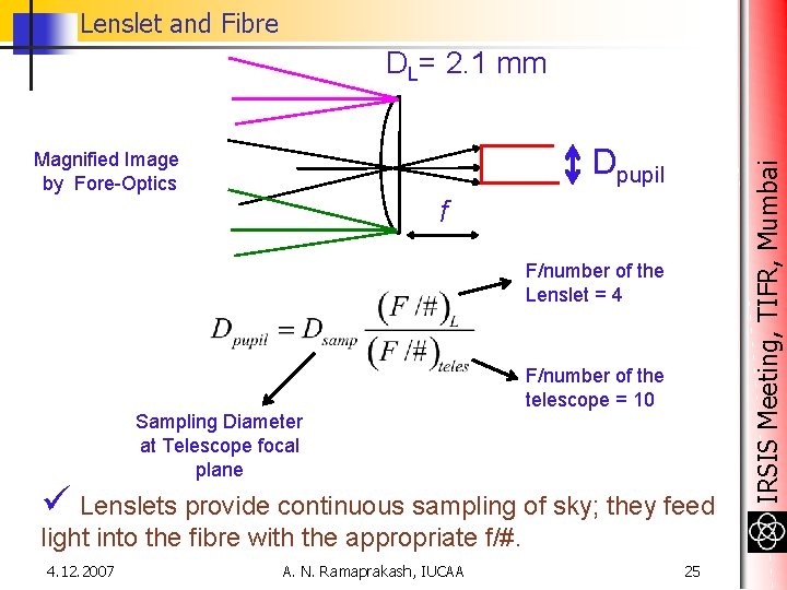
Lenslet and Fibre Dpupil Magnified Image by Fore-Optics f F/number of the Lenslet = 4 F/number of the telescope = 10 Sampling Diameter at Telescope focal plane ü Lenslets provide continuous sampling of sky; they feed light into the fibre with the appropriate f/#. 4. 12. 2007 A. N. Ramaprakash, IUCAA 25 IRSIS Meeting, TIFR, Mumbai DL= 2. 1 mm
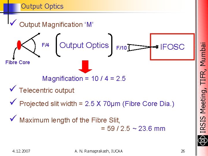
Output Optics F/4 Output Optics F/10 IFOSC Fibre Core Magnification = 10 / 4 = 2. 5 ü Telecentric output ü Projected slit width = 2. 5 X 70μm (Fibre Core Dia. ) ü Maximum length of the Fibre Slit, = 59 / 2. 5 ~ 23. 6 mm 4. 12. 2007 A. N. Ramaprakash, IUCAA 26 IRSIS Meeting, TIFR, Mumbai ü Output Magnification ‘M’
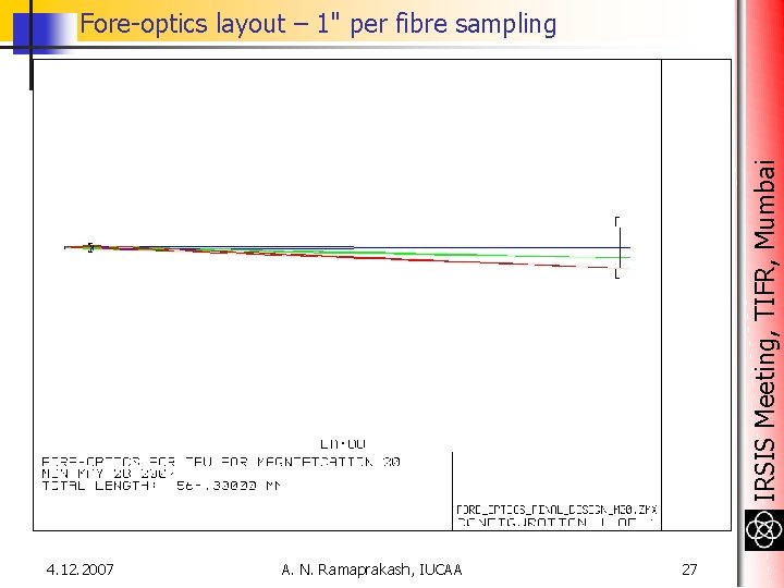
IRSIS Meeting, TIFR, Mumbai Fore-optics layout – 1" per fibre sampling 4. 12. 2007 A. N. Ramaprakash, IUCAA 27
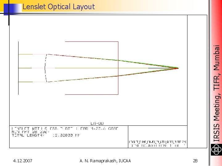
IRSIS Meeting, TIFR, Mumbai Lenslet Optical Layout 4. 12. 2007 A. N. Ramaprakash, IUCAA 28
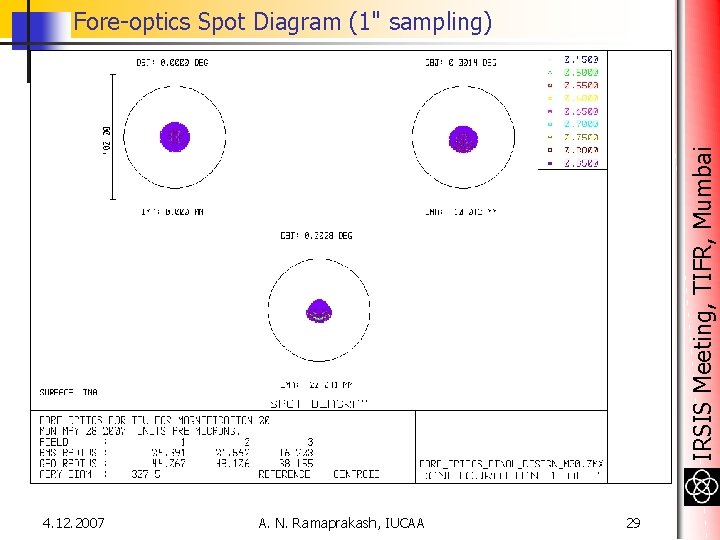
IRSIS Meeting, TIFR, Mumbai Fore-optics Spot Diagram (1" sampling) 4. 12. 2007 A. N. Ramaprakash, IUCAA 29
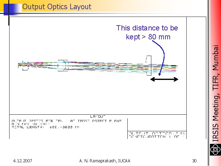
Output Optics Layout IRSIS Meeting, TIFR, Mumbai This distance to be kept > 80 mm 4. 12. 2007 A. N. Ramaprakash, IUCAA 30
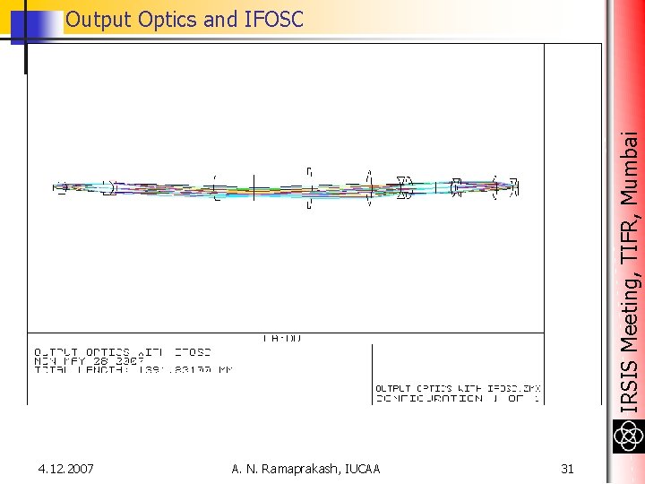
IRSIS Meeting, TIFR, Mumbai Output Optics and IFOSC 4. 12. 2007 A. N. Ramaprakash, IUCAA 31
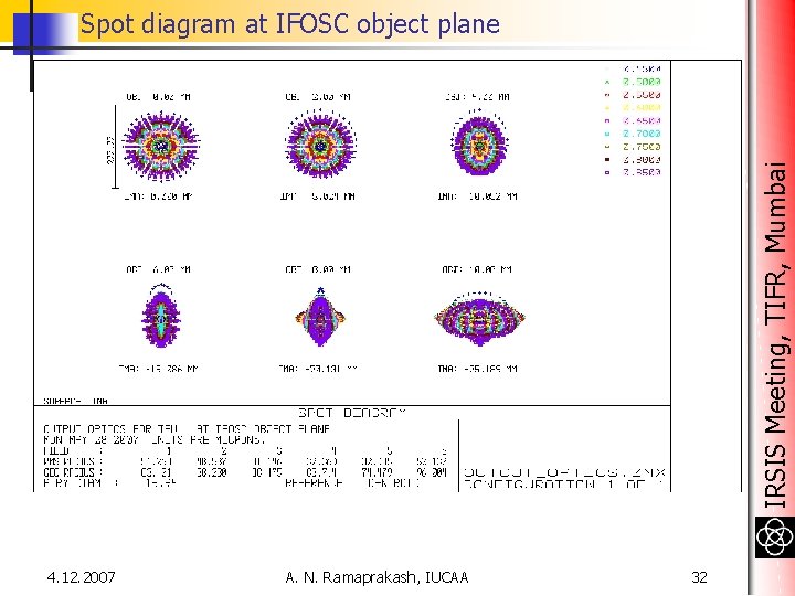
IRSIS Meeting, TIFR, Mumbai Spot diagram at IFOSC object plane 4. 12. 2007 A. N. Ramaprakash, IUCAA 32
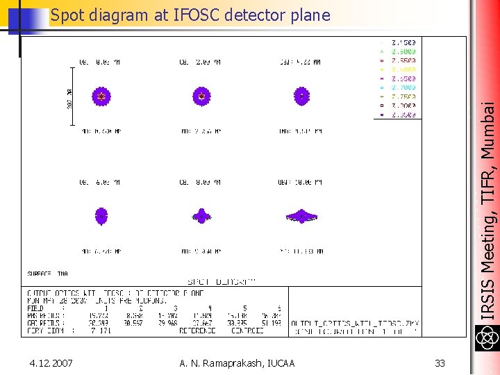
IRSIS Meeting, TIFR, Mumbai Spot diagram at IFOSC detector plane 4. 12. 2007 A. N. Ramaprakash, IUCAA 33
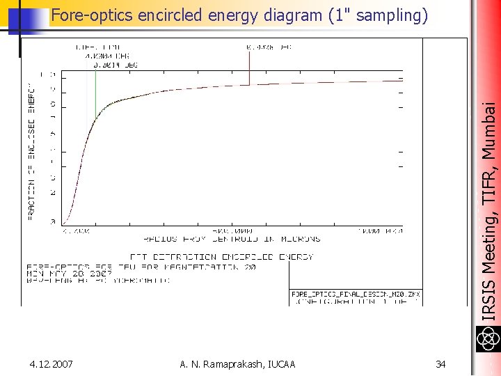
IRSIS Meeting, TIFR, Mumbai Fore-optics encircled energy diagram (1" sampling) 4. 12. 2007 A. N. Ramaprakash, IUCAA 34
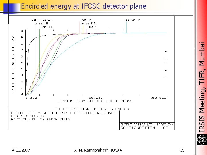
IRSIS Meeting, TIFR, Mumbai Encircled energy at IFOSC detector plane 4. 12. 2007 A. N. Ramaprakash, IUCAA 35
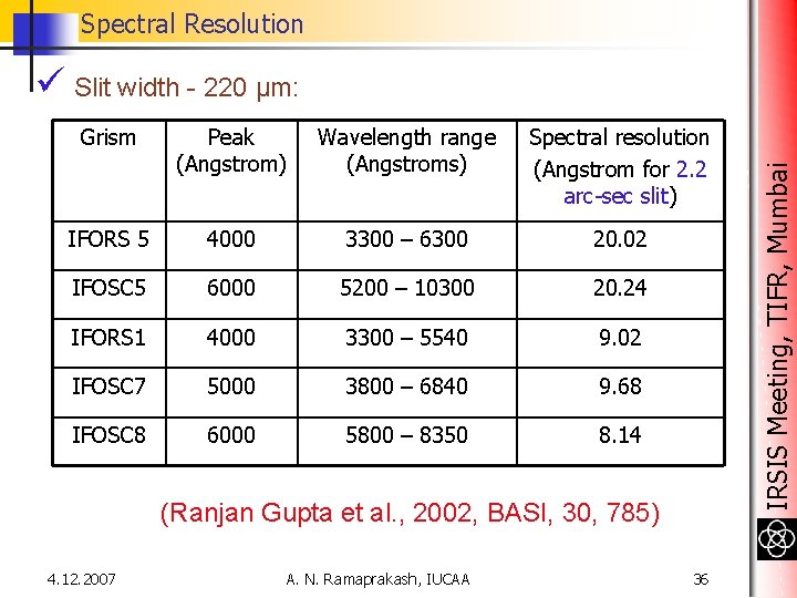
Spectral Resolution Grism Peak (Angstrom) Wavelength range (Angstroms) Spectral resolution (Angstrom for 2. 2 arc-sec slit) IFORS 5 4000 3300 – 6300 20. 02 IFOSC 5 6000 5200 – 10300 20. 24 IFORS 1 4000 3300 – 5540 9. 02 IFOSC 7 5000 3800 – 6840 9. 68 IFOSC 8 6000 5800 – 8350 8. 14 (Ranjan Gupta et al. , 2002, BASI, 30, 785) 4. 12. 2007 A. N. Ramaprakash, IUCAA 36 IRSIS Meeting, TIFR, Mumbai ü Slit width - 220 μm:
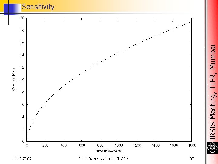
IRSIS Meeting, TIFR, Mumbai Sensitivity 4. 12. 2007 A. N. Ramaprakash, IUCAA 37