
Amedeo Staiano Istituto Nazionale di Fisica Nucleare Torino
- Slides: 23
Amedeo Staiano, Istituto Nazionale di Fisica Nucleare, Torino Development of Ultra-Fast Silicon Detectors for 4 D Tracking N. Cartiglia 1, G. F. Dalla Betta 2, F. Ficorella 3, M. Boscardin 3, G. Paternoster 3, L. Pancheri 2, F. Cenna 1, 4, M. Ferrero 1, V. Sola 1, 4, R. Arcidiacono 1, 5, M. Obertino 1, 4, V. Monaco 1, 4, R. Bellan 1, 4, A. Staiano 1, S. Durando 1, 4 1 Istituto Nazionale di Fisica Nucleare, Torino, Italy 2 Universita' di Trento, Italy 3 Fondazione Bruno Kessler, Trento, Italy 4 Universita' di Torino, Italy 5 Universita' Piemonte Orientale, Torino, Italy Milton Keynes 3 -8 Sep 2017 1
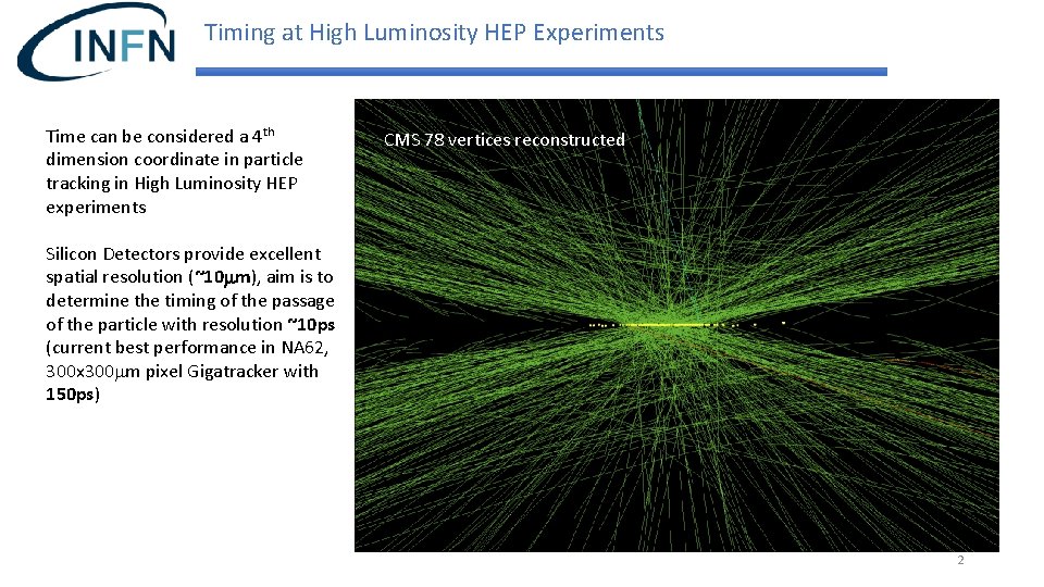
Timing at High Luminosity HEP Experiments Time can be considered a 4 th dimension coordinate in particle tracking in High Luminosity HEP experiments CMS 78 vertices reconstructed Silicon Detectors provide excellent spatial resolution (~10 mm), aim is to determine the timing of the passage of the particle with resolution ~10 ps (current best performance in NA 62, 300 x 300 mm pixel Gigatracker with 150 ps) 2
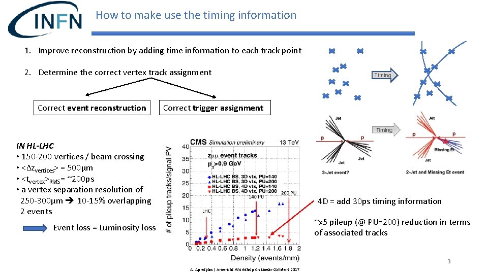
How to make use the timing information 1. Improve reconstruction by adding time information to each track point 2. Determine the correct vertex track assignment Correct event reconstruction Timing Correct trigger assignment IN HL-LHC • 150 -200 vertices / beam crossing • <Δzvertices> = 500μm • <tvertex>RMS= ~200 ps • a vertex separation resolution of 250 -300μm 10 -15% overlapping 2 events 4 D = add 30 ps timing information ~x 5 pileup (@ PU=200) reduction in terms of associated tracks Event loss = Luminosity loss 3 A. Apresyan | Americas Workshop on Linear Colliders 2017
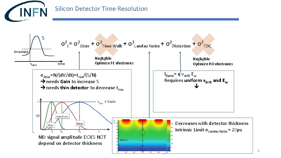
Silicon Detector Time Resolution S σ2 t= σ2 Jitter + σ2 Time Walk + σ2 Landau Noise + σ2 Distortion + σ2 TDC threshold ttrack time Negligible Optimize FE electronics σJitter≈N/(d. V/dt)≈trise/(S/N) needs Gain to increase S needs thin detector to decrease trise Negligible Optimize RO electronics IRamo≈ q vdrift Ew Requires uniform vdrift and Ew GOOD BAD Decreases with detector thickness Intrinsic Limit σLandau Noise ≈ 20 ps NB: signal amplitude DOES NOT depend on detector thickness 4
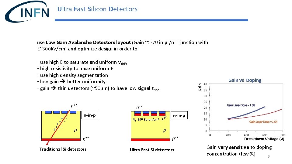
Ultra Fast Silicon Detectors use Low Gain Avalanche Detectors layout (Gain ~5 -20 in p+/n++ junction with E~300 k. V/cm) and optimize design in order to n++ + + - Gain • use high E to saturate and uniform vdrift • high resistivity to have uniform E • use high density segmentation • low gain better uniformity • gain thin detectors (~50μm) to have low signal trise n++ n-in-p p Nd~1016 Boron/cm 3 p+ n-in-p p p++ Traditional Si detectors p++ Ultra Fast Si detectors Breakdown Voltage (V) Gain very sensitive to doping concentration (few %) 5
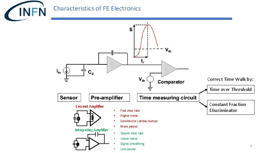
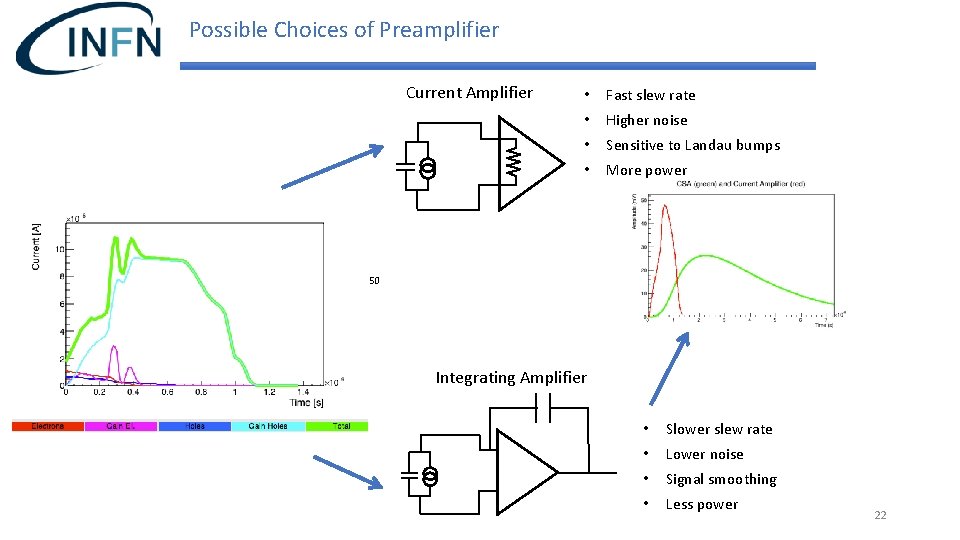
Characteristics of FE Electronics Correct Time Walk by: Time over Threshold Current Amplifier Integrating Amplifier • • Fast slew rate • • Slower slew rate Constant Fraction Discriminator Higher noise Sensitive to Landau bumps More power Lower noise Signal smoothing Less power 6
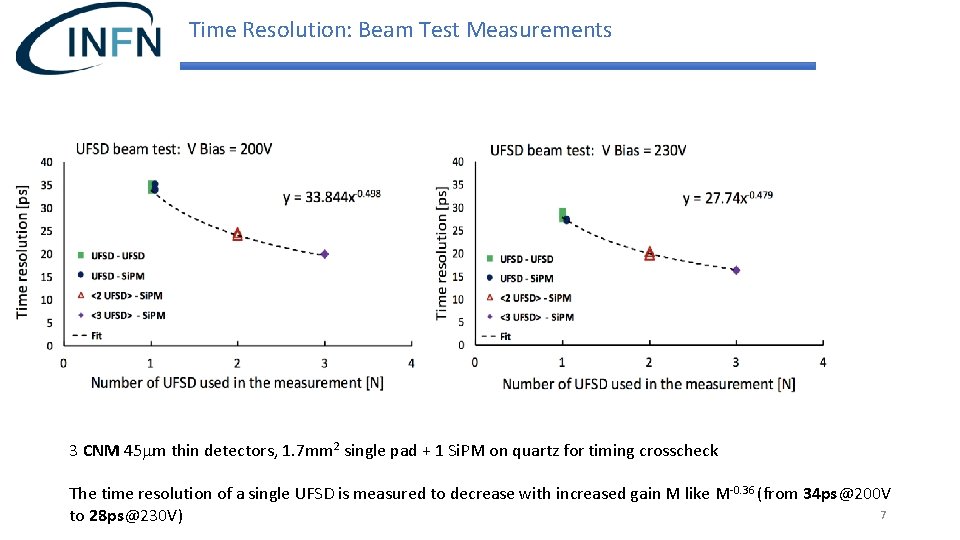
Time Resolution: Beam Test Measurements 3 CNM 45 mm thin detectors, 1. 7 mm 2 single pad + 1 Si. PM on quartz for timing crosscheck The time resolution of a single UFSD is measured to decrease with increased gain M like M-0. 36 (from 34 ps@200 V 7 to 28 ps@230 V)
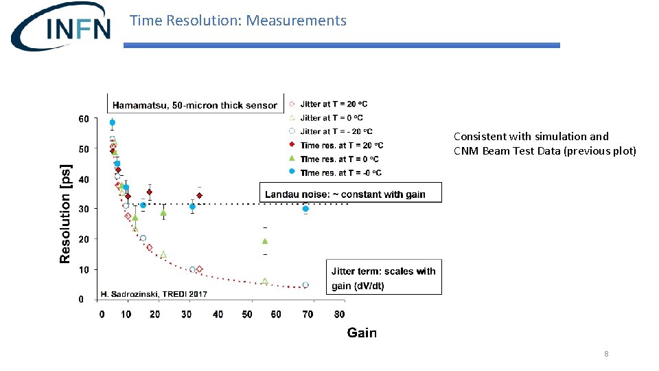
Time Resolution: Measurements Consistent with simulation and CNM Beam Test Data (previous plot) 8
Radiation Tolerance LGAD radiation tolerance studied within the CERN RD 50 collaboration Radiation fluences requested to operate at HL-LHC ~5 1015 particles/cm 2 , radiation doses of 150 Mrad (primarily due to Non-Ionizing Energy Loss) Effects: 1. Same effects of standard n-p Si detectors: increase of Leakage Current (decrease T), increase of V BD and VFD, due to increase of doping concentration. Creation of trapping centers (minimize the effect going to thin sensors (!)) 2. In LGAD: 1. Further increase of leakage current (and power) due to gain layer: go thin, keep gain low 2. Gain loss due to gain layer acceptor removal. Boron atoms are displaced and become interstitial, thus not contributing to the doping profile: increase Vbias, change acceptor (add Carbon to decrease interstitial phase space, and replace Boron with Gallium) 9
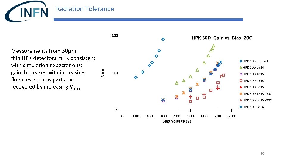
Radiation Tolerance Measurements from 50 mm thin HPK detectors, fully consistent with simulation expectations: gain decreases with increasing fluences and it is partially recovered by increasing VBias 10
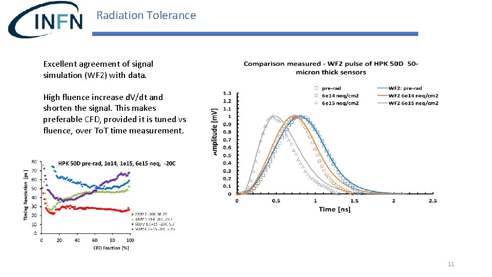
Radiation Tolerance Excellent agreement of signal simulation (WF 2) with data. High fluence increase d. V/dt and shorten the signal. This makes preferable CFD, provided it is tuned vs fluence, over To. T time measurement. 11
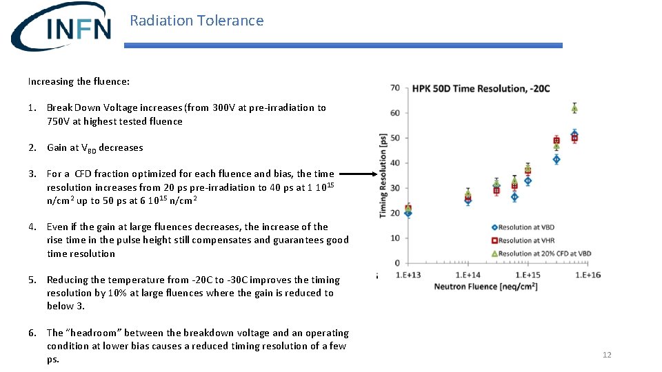
Radiation Tolerance Increasing the fluence: 1. Break Down Voltage increases (from 300 V at pre-irradiation to 750 V at highest tested fluence 2. Gain at VBD decreases 3. For a CFD fraction optimized for each fluence and bias, the time resolution increases from 20 ps pre-irradiation to 40 ps at 1 1015 n/cm 2 up to 50 ps at 6 1015 n/cm 2 4. Even if the gain at large fluences decreases, the increase of the rise time in the pulse height still compensates and guarantees good time resolution 5. Reducing the temperature from -20 C to -30 C improves the timing resolution by 10% at large fluences where the gain is reduced to below 3. 6. The “headroom” between the breakdown voltage and an operating condition at lower bias causes a reduced timing resolution of a few ps. 12
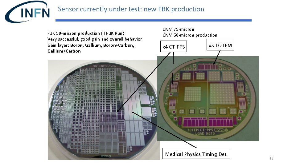
Sensor currently under test: new FBK production FBK 50 -micron production (II FBK Run) Very successful, good gain and overall behavior Gain layer: Boron, Gallium, Boron+Carbon, Gallium+Carbon CNM 75 -micron CNM 50 -micron production x 4 CT-PPS x 3 TOTEM Medical Physics Timing Det. 13
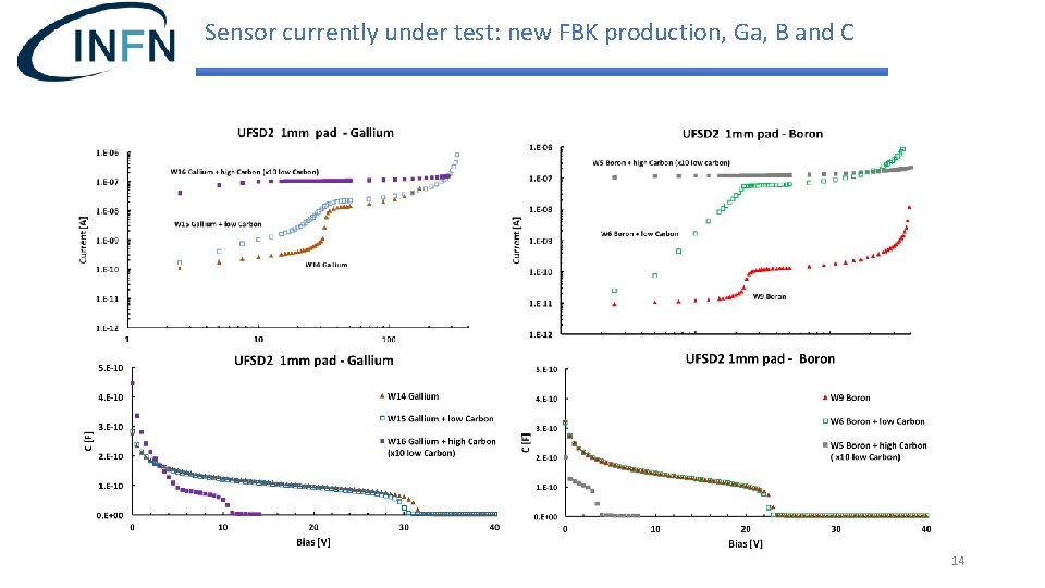
Sensor currently under test: new FBK production, Ga, B and C 14
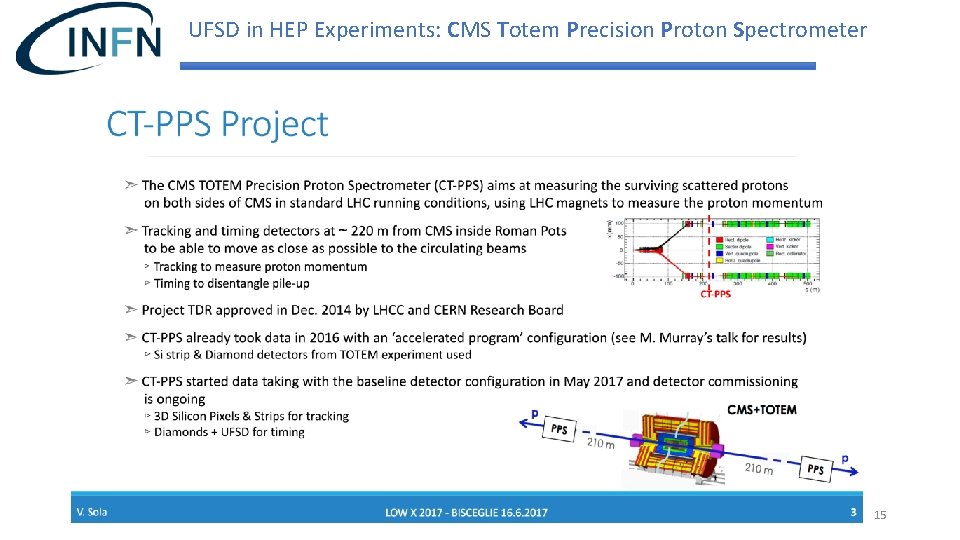
UFSD in HEP Experiments: CMS Totem Precision Proton Spectrometer 15
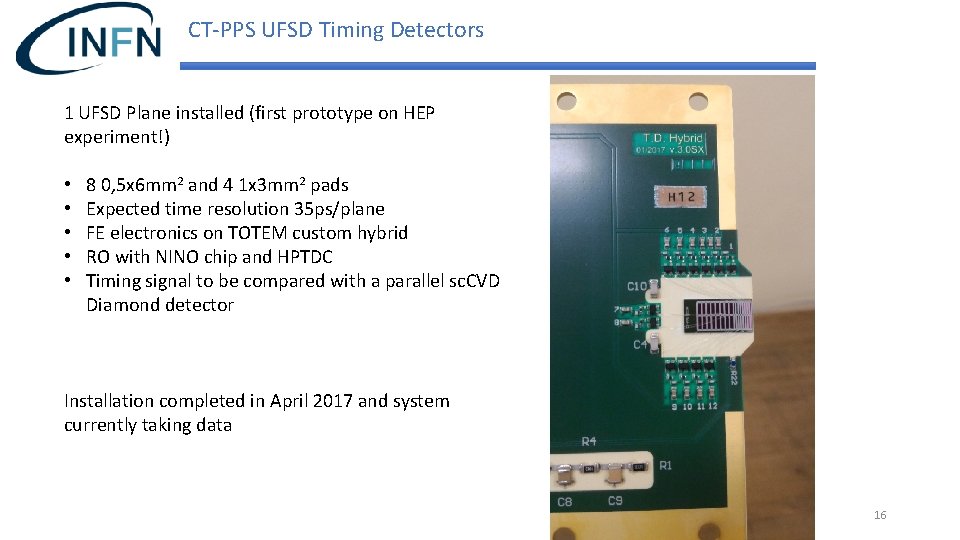
CT-PPS UFSD Timing Detectors 1 UFSD Plane installed (first prototype on HEP experiment!) • • • 8 0, 5 x 6 mm 2 and 4 1 x 3 mm 2 pads Expected time resolution 35 ps/plane FE electronics on TOTEM custom hybrid RO with NINO chip and HPTDC Timing signal to be compared with a parallel sc. CVD Diamond detector Installation completed in April 2017 and system currently taking data 16
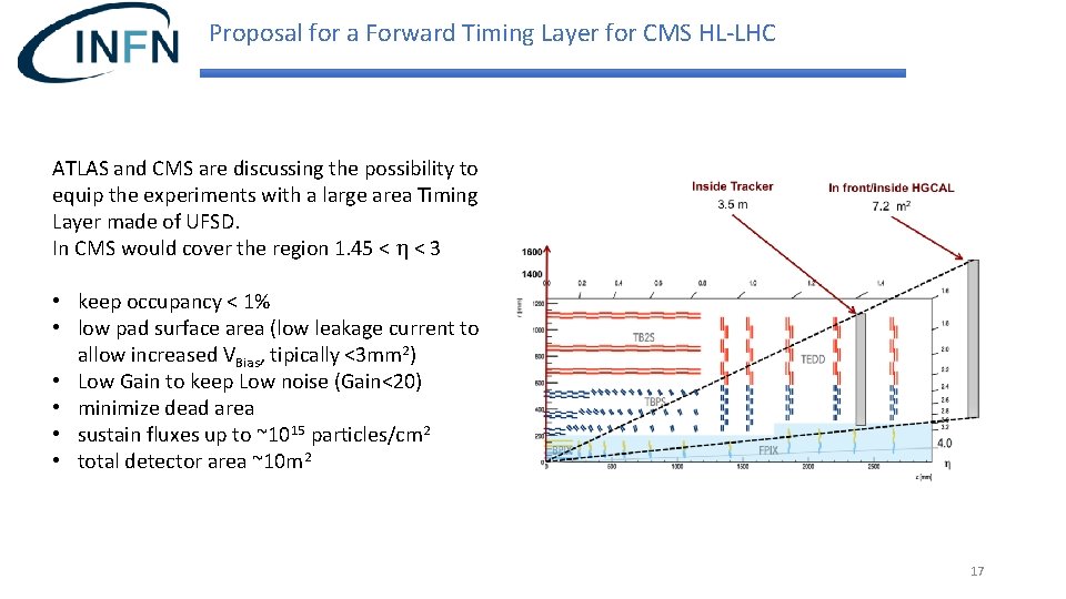
Proposal for a Forward Timing Layer for CMS HL-LHC ATLAS and CMS are discussing the possibility to equip the experiments with a large area Timing Layer made of UFSD. In CMS would cover the region 1. 45 < h < 3 • keep occupancy < 1% • low pad surface area (low leakage current to allow increased VBias, tipically <3 mm 2) • Low Gain to keep Low noise (Gain<20) • minimize dead area • sustain fluxes up to ~1015 particles/cm 2 • total detector area ~10 m 2 17
UFSD Summary • Good results on timing capabilities (~30 ps from beam test) • Good results after NIEL at 6 1015 neq/cm 2, levels to be considered in HL-LHC. New implants (Ga, C) currently under test (last FBK run) • Good agreement with simulations (WF 2 and TCAD) • Technological interest, many manufacturers (CNM (Spain), FBK (Italy), HPK (Japan), Micron Semiconductor (UK)) 18
Acknowledgments Thank you for your attention ! This work was supported by the United States Department of Energy, grant DE-FG 02 -04 ER 41286. Part of this work has been financed by the European Union’s Horizon 2020 Research and Innovation funding program, under Grant Agreement no. 654168 (AIDA-2020) and Grant Agreement no. 669529 (ERC UFSD 669529), and by the Italian Ministero degli Affari Esteri and INFN Gruppo V. 19
BACKUP SLIDES 20
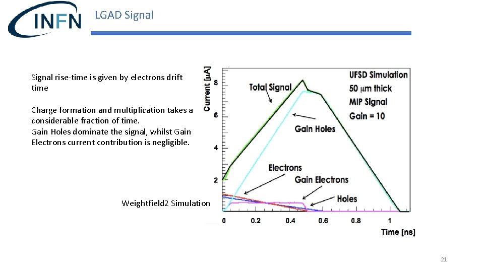
LGAD Signal rise-time is given by electrons drift time Charge formation and multiplication takes a considerable fraction of time. Gain Holes dominate the signal, whilst Gain Electrons current contribution is negligible. Weightfield 2 Simulation 21
Possible Choices of Preamplifier Current Amplifier • Fast slew rate • Higher noise • Sensitive to Landau bumps • More power Current signal in a 50 mm sensor Integrating Amplifier • Slower slew rate • Lower noise • Signal smoothing • Less power 22
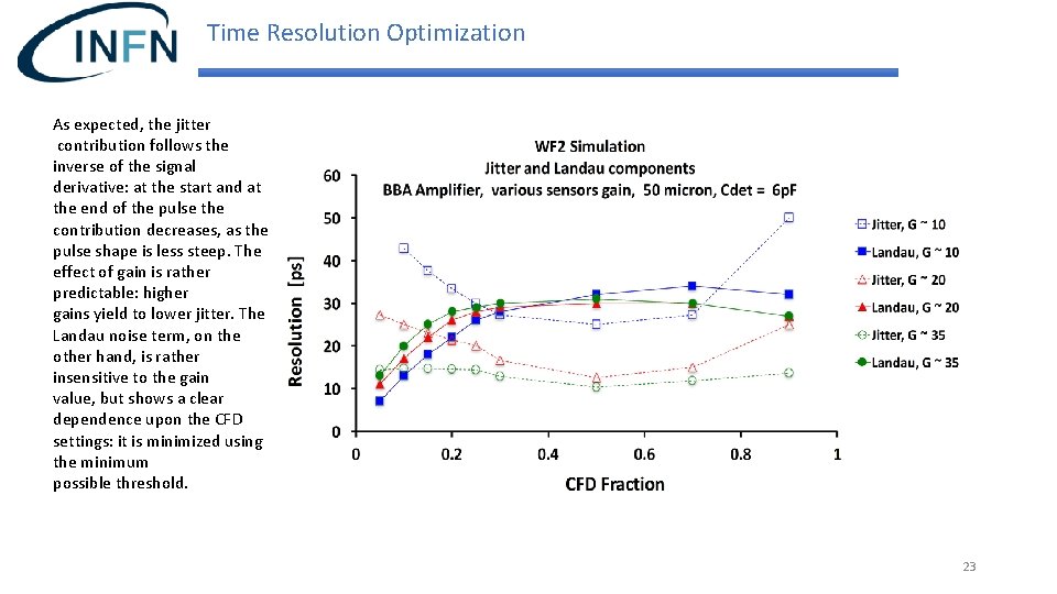
Time Resolution Optimization As expected, the jitter contribution follows the inverse of the signal derivative: at the start and at the end of the pulse the contribution decreases, as the pulse shape is less steep. The effect of gain is rather predictable: higher gains yield to lower jitter. The Landau noise term, on the other hand, is rather insensitive to the gain value, but shows a clear dependence upon the CFD settings: it is minimized using the minimum possible threshold. 23