Alternating current ac is the primary source of
 is the primary source of electrical energy. Synchronous - Machine")

 Synchronous Machines: • Synchronous Generators: A primary source of electrical energy. • Synchronous")
 Machines Require DC excitation to be supplied to the rotor")


 = E P 120 f 2")


 loads, the phase (and terminal) voltage decreases significantly. 2. For unity")


- Slides: 30
Alternating current (ac) is the primary source of electrical energy. Synchronous - Machine which always runs at constant speed (synchronous) Unlike induction machines, the rotating air gap field and the rotor in the synchronous machine rotate at the same speed, called the synchronous speed. It is less expensive to produce and transmit alternating current (ac) than direct current (dc). May function as a Synchronous generator (mechanical to electrical) or Synchronous motor (electrical to mechanical)
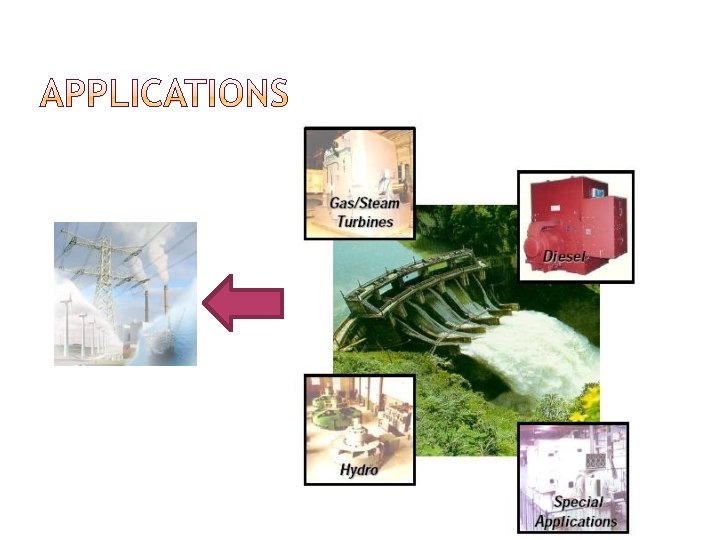
Synchronous machines are ac machine that have a field circuit supplied by an external dc source. �DC field winding on the rotor, �AC armature winding on the stator They are usually large machines generating electrical power at hydro, nuclear, or thermal power stations. Application as a motor: pumps in generating stations, electric clocks, timers, and so forth where constant speed is desired.
i) Synchronous Machines: • Synchronous Generators: A primary source of electrical energy. • Synchronous Motors: Used as motors as well as power factor compensators (synchronous condensers). ii) Asynchronous (Induction) Machines: • Induction Motors: Most widely used electrical motors in both domestic and industrial applications. • Induction Generators: Due to lack of a separate field excitation, these machines are rarely used as generators.
Synchronous Machines Asynchronous (Induction) Machines Require DC excitation to be supplied to the rotor windings Do not require DC excitation Require a DC power source for the rotor excitation Do not require external DC power source Require rotor windings (Salient Pole and Cylindrical Pole) Often constructed with conduction bars in the rotor that are shorted together at the ends to form a squirrel cage (Squirrel cage and or wound rotor) Rotor speed operate at synchronous speed N=Ns=120 f/P Require starting mechanism in addition to the mode of operation that is in effect once they reach synchronous speed More efficient Rotor speed less than synchronous speed N < Ns N=Ns(1 -s) Don’t require additional starting mechanism. Three phase motors can start by simply applying power, but single phase require an additional starting circuit Less efficient Require slip rings and brushes to supply rotor excitation Don’t require slip rings, but some require for soft starting or speed control Larger size, expensive and complex Smaller size, cheap and simple
Generator Exciter View of a two-pole round rotor generator and exciter.
The rotor of the generator is driven by a prime-mover A dc current is flowing in the rotor winding which produces a rotating magnetic field within the machine The rotating magnetic field induces a three-phase voltage in the stator winding of the generator E s (t) N sta � Frequency d lin k (t) dt of the induced EMF:
Electrical frequency produced is locked or synchronized to the mechanical speed of rotation of a synchronous generator: Ns 120 f p f Nsp Hz 120 where fe = electrical frequency in Hz P = number of poles nm= mechanical speed of the rotor, in r/min
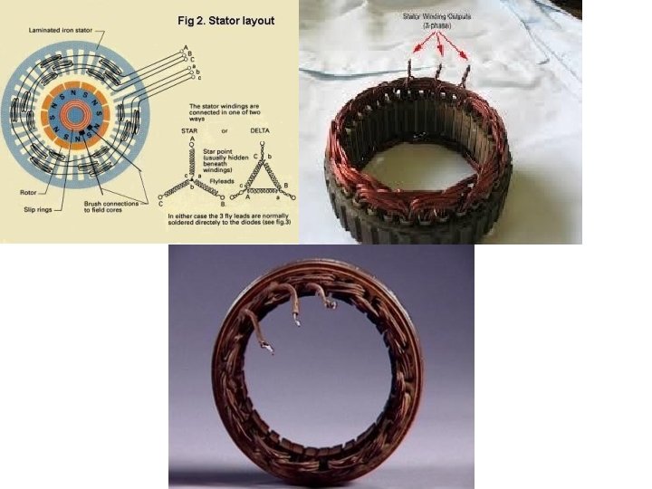
� Two main parts of the AC generator/ Synchronous Generator/ Alternator are: � Stator � Rotor � Stator: � � � The stator is a ring shaped laminated iron-core with slots. The stator of a synchronous machine carries the armature or load winding which is a three-phase winding. The armature winding is formed by interconnecting various conductors in slots spread over the periphery of the machine’s stator. Often, more than one independent three phase winding is on the stator. The three separate windings are physically displaced by 120°E.
Laminated ferromagnetic material Voltage is induced in Armature Winding can be either Single layer winding or Double Layer winding
Synchronous machine rotors are simply rotating electromagnets built to have as many poles as are produced by the stator windings. Dc currents flowing in the field coils surrounding each pole magnetize the rotor poles. The magnetic field produced by the rotor poles locks in with a rotating stator field, so that the shaft and the stator field rotate in synchronism. Salient Pole Cylindrical Pole Useful for low speed and large power applications Useful for high speed and high power applications Ex: Hydrogenerators Ex: Turbogenerators Smaller axial length and larger diameter Larger axial length and smaller diameter Non-uniform flux distribution Uniform flux distribution Introduces hormonics in AC waveform No hormonics is introduced in the AC waveform Very expensive Less expensive
D 1 m Turbine L 10 m Steam High speed 3600 r/min -pole 1800 r/min -pole Direct-conductor cooling (using hydrogen or water as coolant) d-axis Stator winding N Uniform air-gap Stator q-axis Rating up to 2000 MVA Rotor winding Rotor S Turbogenerator
Synchronous Machine – Cylindrical rotor Stator Cylindrical rotor
Synchronous Machine – Salient Pole 1. Most hydraulic turbines have to turn at low speeds (between 50 and 300 r/min) 2. A large number of poles are required on the rotor d-axis Non-uniform air-gap N D 10 m q-axis S S Turbine Hydro (water) Hydrogenerator N
� According to Faraday’s law: E d dt � In one revolution of the rotor (i. e in 60/N sec) each stator conductor is cut by a flux of ΦP wb. dt d P 60 and N � Average induced EMF per conductor is= d P = P x N E 60/N 60 dt � Now, we know that, Ns 120 f p
� Average EMF induced per conductor is (v) = E P 120 f 2 f 60 P � If there are Z conductors in series/phase, then the average emf/phase in (v)= E 2 f Z � If Z = 2 T (T is no of coils or turns/phase) � Then, the average induced EMF in an alternator is, E 4 f T � The rms value of induced EMF in an alternator is, E 1. 11*4 f T 4. 44 f T
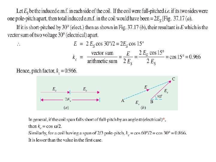
� The above said equation is used for computing the induced EMF of an alternator is the stator conductors (or coils) are full pitched, concentrated (bunched in one slot rather than distributed). � If it’s a short pitch coil and distributed winding means, then the resultant induced EMF of an alternator is, E 4. 44 kp kd f T � Coil pitch factor (kp) is k p cos / 2 k sin(m / 2) � Distribution factor (kd) is d m sin( / 2)
• If the coil sides are placed in slots 1 and 7, then it is fullpitched. • If the coil sides are placed in slots 1 and 6, then it is shortpitched or fractional-pitched because coil span is equal to 5/6 of a pole-pitch. • It falls short by 1/6 pole-pitch or by 180°/6 = 30°. • Short-pitched coils are used because of the following advantages: • 1. They save copper of end connections. 2. They improve the wave-form of the generated e. m. f. i. e. the generated e. m. f. can be made to approximate to a sine wave more easily and the distorting harmonics can be reduced or totally eliminated. 3. Due to elimination of high frequency harmonics, eddy current and hysteresis losses are reduced thereby increasing the efficiency. • disadvantage of using short-pitched coils is that the total voltage around the coils is somewhat reduced. Because the voltages induced in the two sides of the short-pitched coil are slightly out of phase, their resultant vectorial sum is less than their arithmetical sum.
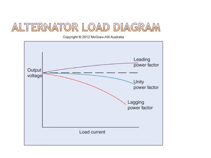
the load on the alternator is varied, its terminal voltage is also found to vary as DC generators. This variation in terminal voltage V is due to the following reasons: � As � Voltage drop due to Armature resistance Ra � Voltage drop due to Leakage reactance XL The armature flux produced in the armature conductor does not cross the airgap and it takes its own path is called as Leakage flux. � Voltage drop due to Armature reaction Xa In case of Alternator, power factor of the load determines the effect of armature reaction. Types of Load: (I) Unity Power factor (Resistive) (II) Lagging power factor (Inductive) (III) Leading power factor (Capacitive)
� Synchronous Reactance: The total reactance's offered under loaded condition of the alternator is called Synchronous reactance (Xs) Xs=XL+Xa � Synchronous Impedance: The total impedances (opposition) offered to the flow of current to the load in an alternator is called Synchronous Impedance (Zs) Z R 2 X s a 2 s
E E Induced EMF Equation? E
For lagging (inductive) loads, the phase (and terminal) voltage decreases significantly. 2. For unity power factor (purely resistive) loads, the phase (and terminal) voltage decreases slightly. 3. For leading (capacitive) loads, the phase (and terminal) • voltage rises 4. Effects of adding loads can be described by the voltage regulation: 1. • The voltage regulation of an alternator can be calculated: • VR% = ((VNL – VFL)/VFL) x 100% • Where: • VR% = % voltage regulation; VNL= no load voltage in V VFL = full load voltage in V
Example 1 • A hydraulic turbine machine turning at 200 rpm is connected to a synchronous generator. If the induced voltage has a frequency of 60 Hz, how many poles does the rotor have? • Solution: • P=120 f/N • =120 x 60 / 200 • =36 poles
Example 2 • A 6 pole AC generator is running and producing at the frequency of 60 Hz. Calculate the revolutions per minute of the generator. If the frequency is reduced to 20 Hz, how many number of poles will be required if the generator is to be run at the same speed? • Frequency generated, f = 60 Hz • Number of poles, P = 6 • Speed, N = 120 f / P = • =120 x 60 / 6 • = 1200 rpm • When frequency f’ = 20 Hz • Number of poles required, P’ = 120 f’ / N = 120 x 20 / 1200 • = 2 poles
Example • Difference between DC and AC generator. • In DC generators, the armature rotates and the field system is stationary • The arrangement in alternators is just the reverse of it. • In AC generator standard construction consists of • armature winding mounted on a stationary element called stator and • field windings on a rotating element called rotor.
An alternator on open-circuit generates 360 V at 60 Hz when the field current is 3. 6 A. Neglecting saturation, determine the open-circuit e. m. f. when the frequency is 40 Hz and the field current is 2. 4 A As seen from the e. m. f. equation of an alternator, In a DC machine, the induced emf E increases as the field current increases. But after a certain level, the core saturates and the flux remains constant even if the field current increases. So, therefore when input current exceeds a particular limit, the output remains constant.
A motor generator set used for providing variable frequency a. c. supply consists of a three-phase, 10 -pole synchronous motor and a 24 -pole, three- phase synchronous generator. The motor-generator set is fed from a 25 Hz, three-phase a. c. supply. A 6 -pole, three phase induction motor is electrically connected to the terminals of the synchronous generator and runs at a slip of 5%. Determine : (i) the frequency of the generated voltage of the synchronous generator. (ii) the speed at which the induction motor is running. Speed of synchronous motor = (120 × 25)/10 = 300 rpm At 300 rpm, frequency of the voltage generated by 24 -pole synchronous generator Synchronous speed of the 6 -pole induction motor fed from a 60 Hz supply (ii) With 5 % slip, the speed of this induction motor = (1 -0. 05) x 1200 = 1140 rpm the frequency of the rotor-currents = s f = 0. 05 x 60 = 3 Hz