Alpha College of Engg Tech Khatraj Gandhinagar EEE2110005
 1 st SEM EE-A Group")


 circuit consisting of")


 • Reactive")


- Slides: 21
Alpha College of Engg & Tech Khatraj, Gandhinagar EEE(2110005) 1 st SEM EE-A Group 5 1 KOTADIA SMIT SATISHKUMAR (130510109034 ) 2 BHANUSHALI SHREYABEN DINESHKUMAR (130510109005 ) 3 BHAVSAR JAY KANAIYALAL (130510109007 ) 4 PATEL AMISHKUMAR MAHENDRABHAI (130510109054 ) 5 SHAH YASH VIPUL (130510109111 ) 6 PATEL DHRUVKUMAR BHARATBHAI (130510109059 ) Faculty Name: 1 Prof. Narendra C. Mahavadia 2 Mr. Tushit M Desai
Topic Ø Power Triangle Ø Active , Reactive & Apparent power Ø Method of Power Factor Improvement
Power Triangle �When each component in fig. is multiplied by a voltage V, a Power Triangle is obtained as shown in fig.
Power diagram for inductive loads. Power diagram for capacitive loads.
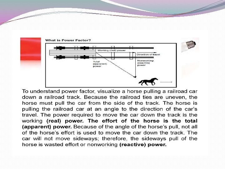
True, reactive, and apparent power �In a simple alternating current (AC) circuit consisting of a source and a linear load, both the current and voltage are sinusoidal. If the load is purely �resistive, the two quantities reverse their polarity at the same time. At every instant the product of voltage and current is positive, indicating that the �direction of energy flow does not reverse. In this case, only real power is transferred.
�If the loads are purely reactive, then the voltage and current are 90 degrees out of phase. For half of each cycle, the product of voltage and current is �positive, but on the other half of the cycle, the product is negative, indicating that on average, exactly as much energy flows toward the load as flows �back. There is no net energy flow over one cycle. In this case, only reactive energy flows—there is no net transfer of energy to the load. �Practical loads have resistance, inductance, and capacitance, so both real and reactive power will flow to real loads. Power engineers measure apparent �power as the magnitude of the vector sum of real and reactive power. Apparent power is the product of the rootmean-square of voltage and current.
�Conventionally, capacitors are considered to generate reactive power and inductors to consume it. If a capacitor and an inductor are placed in parallel, �then the currents flowing through the inductor and the capacitor tend to cancel rather than add. This is the fundamental mechanism for controlling the �power factor in electric power transmission; capacitors (or inductors) are inserted in a circuit to partially cancel reactive power 'consumed' by the load.
S Q P • True power, P, or active power: watt (W) • Reactive power, Q: volt-ampere reactive (var) • Apparent power, |S|: the magnitude of complex power S: volt-ampere (VA) • Phase of voltage relative to current, φ: the angle of difference (in degrees) between voltage and current; current lagging voltage (quadrant I vector), current leading voltage (quadrant IV vector)
Active Power �Instantaneous power to a load is p = v • i �In an ac circuit �p may be positive sometimes and negative other times �Average value of the power, P �Real power �Average value of instantaneous power, real power, active power, and average power mean the same thing
Reactive Power �During times when p is negative, power is being returned from load �This can happen for inductive or capacitive loads �Power that flows into these loads and back out is called the reactive power �Average value of reactive power is zero
Active and Reactive Power Equations �P = VI cos = S cos �Q = VI sin = S sin �V and I are RMS values � is the phase angle between V and I �Q is positive for inductive circuits and negative for capacitive circuits
Apparent Power �Power to a load is VI �If load has both resistance and reactance �Product is neither the real power nor the reactive power, but a combination of both �This is called the apparent power, S �S = VI = I 2 Z = V 2/Z �Units are volt-amperes (VA) Defining the apparent power to a load.
Power Factor Improvement
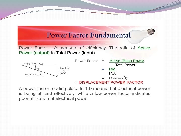
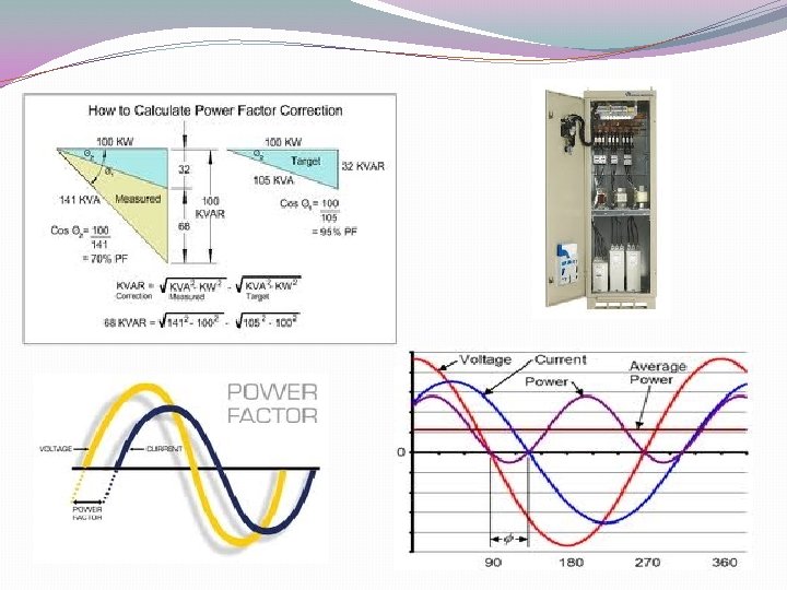
�Ratio of real power to apparent power is called the power factor, Fp �It's a practical measure of the efficiency of a power distribution �system. For two systems transmitting the same amount of real power, the system with the lower power factor will have higher circulating currents due to �energy that returns to the source from energy storage in the load. These higher currents produce higher losses and reduce overall transmission efficiency. �A lower power factor circuit will have a higher apparent power and higher losses for the same amount of real power.
�energy that returns to the source from energy storage in the load. These higher currents produce higher losses and reduce overall transmission efficiency. �A lower power factor circuit will have a higher apparent power and higher losses for the same amount of real power.
�Fp = P/S = cos �Angle is angle between voltage and current �For pure resistance = 0° �For inductance, = 90° �For capacitance, = -90° �For a circuit containing a mixture, is somewhere between 0° and 90° Demonstrating the impact of a capacitive element on the power factor of a network.
�Unity power factor �For a purely resistive circuit, the power factor will be one �For load containing resistance and inductance �Power factor will be less than one and lagging �Current lags the voltage �The power factor is unity (one) when the voltage and current are in phase. It is zero when the current leads or lags the voltage by 90 degrees. Power �factors are usually stated as "leading" or "lagging" to show the sign of the phase angle of current with respect to voltage.
THANK YOU.