Alignment of Magnet Apertures Surveying with Leica Laser


 St. Genis Checkpost Gare Cornavin")


- Slides: 29
Alignment of Magnet Apertures & Surveying with Leica Laser Tracker Module n n n B. Sasidhar Rao Shradha Palod Raghavendra Gangoor
Warm Measurements with Laser Tracker Module n Alignment of magnet with bench at CFB and MRB sides. n n n Required when magnetic measurements are done on a magnet , eases insertion of shaft Especially with SSSS, when the bench is not exactly confirming to the magnet geometry Surveying n Required with SSW measurement to find the position of stretch wire
LASER Tracker Module • The laser tracker is a transportable 3 D measuring system, measuring vertical and horizontal angles as well as interferometric or absolute distances. • The laser tracker used is the LEICA LTD 500. • Consisting of the central Tracking unit, LT Controller unit, Reflectors, application s/w, Level meter, Laptop, hardware lock etc.
Introduction to measurement with Laser Tracker n n This is Laser Interferometer which tracks a moving retro-reflector via a motorised mirror Permits real time distance measurements Once the laser beam locks onto the reflector it tracks and displays reflector’s position continuosly until the beam is broken Reflectors used for different applications n n Corner Cube Reflector (CCR) Tooling Ball Reflector (TBR)
Trilateration principle(2 D) St. Genis Checkpost Gare Cornavin
Alignment of Magnet with Leica Laser Tracker
Features of Laser Tracker • • Fully automatic tracking system as a huge amount of magnets has to be measured Automatic measurement inside a tube of 50 mm and 15 m length An accuracy better than 0. 1 mm and reliability using redundancy Transportability as the works take place in different places
Requirement for magnet alignment Dipoles n n Compliance to geometric tolerance limits To check bended shape (tolerance is +/- 1 mm) for mechanical aperture To measure position of alignment references • n n Quadrupole n To facilitate smooth insertion of shaft for magnetic measurements Requirements n Compliance to geometric tolerance limits n High Precision n Measurement Portability Solution: Laser Tracker along with suitable Mole
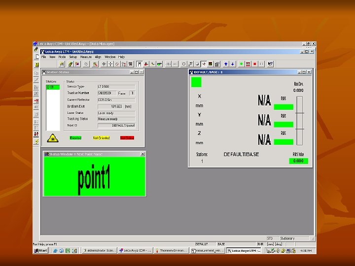
Alignment Procedure n n Leica Set up Orient to Gravity Measurement Analysis of result
Leica Set up n Warm up of Laser – takes about 15 min n Start temperature and pressure monitoring n Fixing position of Leica so that tracking is possible till the end of the magnet without losing the beam n n 2 to 3 iterations are required for exact positioning. Levelling
Orient to Gravity n n Orient to gravity is done using NIVEL level sensor It is used to set leica’s primary( standing) axis very close to gravity (vertical) n Any residual tilt is compensated by correcting the measured angles such that they appear to come from an exactly levelled instrument
Measurement n n n Creation of Station for each measurement Select the type of reflector being used Install mole in the magnet aperture and attach reflector on the mole Mole Reflector
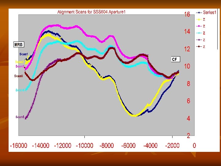
Analysis of Result n n After the leica scans for the full magnet length, the results are available for analysis Translation of co-ordinate axis is done such that (0, 0, 0) point is transformed onto the CFB of the magnet aperture for which alignment is carried out Plotting the results in the excel sheet for analysis Repeatation of the measurement till alignment is within acceptable tolerance ( < 2 mm)
Surveying of Magnet axis with Leica Laser Tracker
Aim n n n A laser tracker system is used to survey the SSW system and the magnet in order to link the magnetic axis to the magnet fiducials By this one can get exact location of stretch wire inside the magnet, which is used to compute the magnetic axis Global Survey Accuracy : 50 -100 microns
Surveying Procedure n Build a network of points in 3 -D space n As it is impossible to “ see” all fiducials of both SSW stages and magnet from one single location, the entire survey is performed from two different positions n Installation of Leica and survey at CFB side n Installation of Leica and survey at MRB side n Analysis of measured data
Building a network of 3 -D points in Space n n n Points used for networking should be carefully identified The points should be such that at least 3 common points are visible from both the stations. A large number of points should be measured for better accuracy The points should be stable, fix and should not be disturbed till the entire measurement is completed
Stage B Survey Points Stage A Survey Points
Stations Location Tracker location for station 2 Tracker location for station 1 RP 2 RP 4 RP 1 RP 3 MLI CFB MC SSS SSW Stage A MLE SSW Stage B RP
Definition of measurement points
Surveying of network points Station at MRB Side Station at CFB Side Surveying of fiducial points
Installation of Leica and Survey at CFB side n Set up of Leica - as already explained n Orient to Gravity n Static measurements of network points, magnet fiducials and SSW stage-B X & Y positions n n In Static measurements, the distance between home position (bird bath) of tracker and the respective point is measured Depending on the location of measuring point , appropriate reflector holder should be chosen
Installation of Leica and Survey at MRB side n Set up of Leica n n n Has to be repeated since the position of Leica is changed Orient to Gravity not required Static measurements of network points, magnet fiducials and SSW stage-A X & Y positions
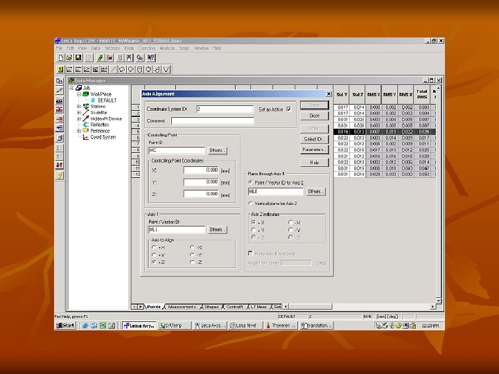
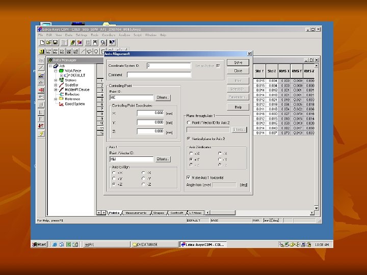
Analysis of measured data n n Orient to network n As soon as all points have been measured on the two stations, a network orientation is required, to set all points in one referential Solving the network to achieve Axis Alignment n For the magnet’s fiducials to become the coordinate system of the measurement
Thank You