Aliasing DC Aliasing From The DSP Handbook Algorithms


Aliasing DC 成分的假訊號產生稱為 Aliasing, 可簡單說明如圖 From The DSP Handbook: Algorithms, Applications and Design Techniques by Andrew Bateman, Iain Paterson. Stephens, 2002


Resolution & S/N Ratio 據以計算 S/N Ratio 為

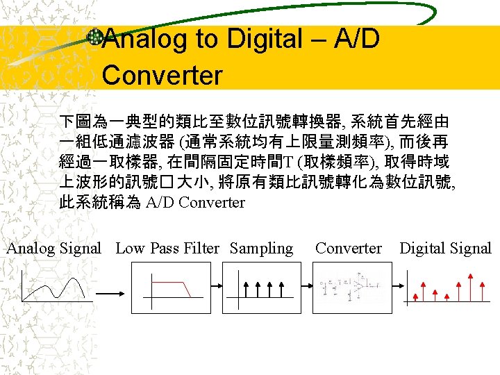
Other Performance Index of A/D Converter A/D轉換時間: 4 us min for example A/D解析度: 8 bit ~ 16 bit (24 bit is the best one now) A/D電壓範圍 +/- 30 V ~ +/- 5 m. V for example 放大器增益: 1, 8, 64, 512 for example 頻道數: 16 for example 雜訊比(S/N Ratio): 78 d. B for 14 bit …. . Integral Linearity: 0. 0015% FS for example Differential Linearity: ± 1. 5 LSB for example 共模電壓(CMV): ± 5 V min for example 共模拒斥比(CMR): ± 80 d. B for example 溫度漂移: 增益: ± 5 ppm/C for example 時間漂移: 增益: ± 27 ppm/yr for example

A/D Converter Structure A direct conversion ADC or flash ADC has a comparator that fires for each decoded voltage range. The comparator bank feeds a logic circuit that generates a code for each voltage range. Direct conversion is very fast, but usually has only 8 bits of resolution (256 comparators) or less. ADCs of this type have a large die size, a high input capacitance, and are prone to produce glitches on the output (by outputting an out-of-sequence code). They are often used for video or other fast signals.

A/D Converter Structure A direct conversion ADC From Digital Fundamentals by Floyd, 2002

A/D Converter Structure A delta-encoded ADC has an up-down counter that feeds a digital to analog converter (DAC). The input signal and the DAC both go to a comparator. The comparator controls the counter. The circuit uses negative feedback from the comparator to adjust the counter until the DAC's output is close enough to the input signal. The number is read from the counter. Delta converters have very wide ranges, and high resolution, but the conversion time is dependent on the input signal level. Delta converters are often very good choices to read real-world signals. Most signals from physical systems do not change abruptly.

A/D Converter Structure A delta-encoded ADC From Digital Fundamentals by Floyd, 2002

A/D Converter Structure A successive-approximation ADC uses a comparator to reject ranges of voltages, eventually settling on a final voltage range. For example, the first comparison might decide the most significant bit of the output, the next comparison decides the next-most significant bit, etc. This is also called bit-weighting conversion. ADCs of this type convert very fast, and have good resolutions and quite wide ranges. They are more complex than some other designs.

A/D Converter Structure A successive-approximation ADC From Digital Fundamentals by Floyd, 2002

A/D Converter Structure A Tracking ADC produces a saw-tooth signal that ramps up and tracks the signal. When the ramp starts, a timer starts counting. When the ramp voltage matches the input, a comparator fires, and the timer's value is recorded. Timed ramp converters require the least number of transistors. The ramp time is sensitive to temperature because the circuit generating the ramp is often just some simple oscillator. There are two solutions: use a clocked counter driving a DAC and then use the comparator to preserve the counter's value, or calibrate the timed ramp. A special advantage of the ramp-compare system is that comparing a second signal just requires another comparator, and another register to store the voltage value.

A/D Converter Structure A Tracking ADC From Digital Fundamentals by Floyd, 2002
 uses two or more")
A/D Converter Structure A pipeline ADC (also called subranging quantizer) uses two or more steps of subranging. First, a coarse conversion is done. In a second step, the difference to the input signal is determined with a digital to analog converter (DAC). This difference is then converted finer, and the results are combined in a last step. This type of ADC is fast, has a high resolution and only requires a small die size.

A/D Converter Structure A pipeline ADC
- Slides: 19