
Algorithmic State Machine ASM Register Transfer Level RTL


- Slides: 37
Algorithmic State Machine ASM
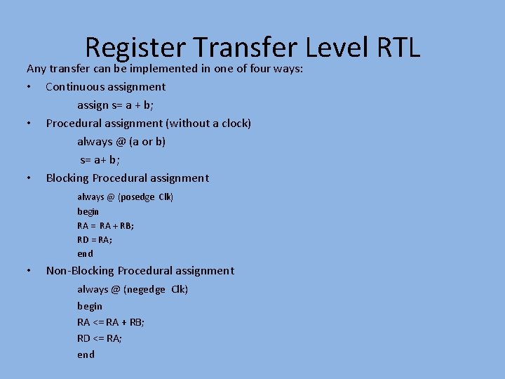
Register Transfer Level RTL Any transfer can be implemented in one of four ways: • • • Continuous assignment assign s= a + b; Procedural assignment (without a clock) always @ (a or b) s= a+ b; Blocking Procedural assignment always @ (posedge Clk) begin RA = RA + RB; RD = RA; end • Non-Blocking Procedural assignment always @ (negedge Clk) begin RA <= RA + RB; RD <= RA; end
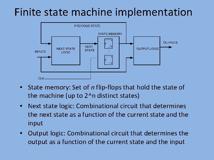
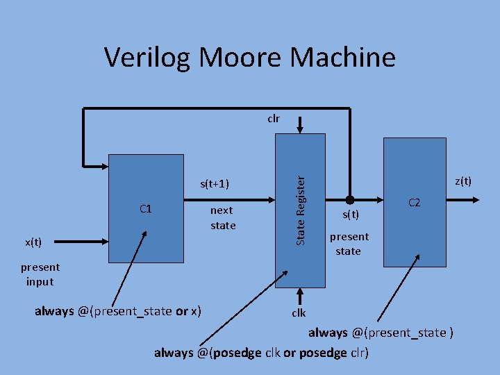
Finite state machine implementation • State memory: Set of n flip-flops that hold the state of the machine (up to 2^n distinct states) • Next state logic: Combinational circuit that determines the next state as a function of the current state and the input • Output logic: Combinational circuit that determines the output as a function of the current state and the input
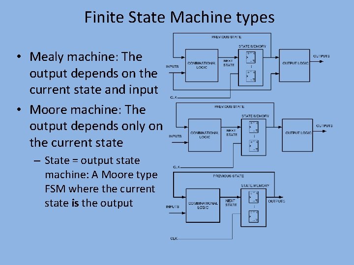
Finite State Machine types • Mealy machine: The output depends on the current state and input • Moore machine: The output depends only on the current state – State = output state machine: A Moore type FSM where the current state is the output
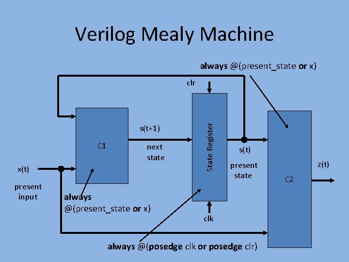
Verilog Mealy Machine always @(present_state or x) s(t+1) C 1 next state x(t) present input always @(present_state or x) State Register clr s(t) present state clk always @(posedge clk or posedge clr) z(t) C 2
Verilog Moore Machine s(t+1) C 1 next state x(t) State Register clr z(t) s(t) C 2 present state present input always @(present_state or x) clk always @(present_state ) always @(posedge clk or posedge clr)
Algorithmic State Machines
Introduction Digital system is specified by the following three components: • The set of registers in the system • The operations that are performed on the data stored in the registers. • The control that supervises the sequences of operations in the system.
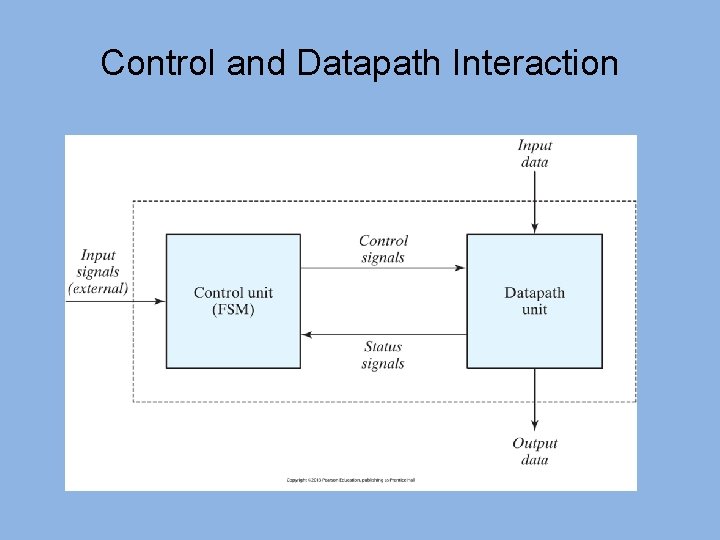
Control and Datapath Interaction
Datapath • Binary information in digital systems classified as either data or control. • Data – bits of information manipulated by performing arithmetic and logic operations. • Hardware components realizing above operations are adders, decoders, multiplexers, counters e. t. c
Control Path • Command signals used to supervise execution of algorithms by datapath. • Bi-directional communication with datapath through status conditions used to determine the sequence of control signals. • Control logic inherently sequential. • Control logic is usually implemented using FSMs
Algorithm Implementation • Often we have to implement an algorithm in hardware instead of software • Algorithm is a well defined procedure consisting of a finite number of steps to the solution of a problem. • It is often hard to translate the algorithm into an FSM. • ASMs can serve as stand-alone sequential network model.
Algorithmic State Machine • Used to graphically describe the operations of an FSM more concisely • Resembles conventional flowcharts – differs in interpretation. • Conventional flowchart – sequential way of representing procedural steps and decision paths for algorithm -No time relations incorporated • ASM chart – representation of sequence of events together with timing relations between states of sequential controller and events occurring while moving between steps
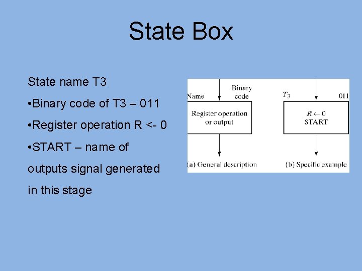
ASM Chart • Three basic elements: state box, decision box and conditional box -State and decision boxes used in conventional flowcharts -Conditional box characteristic to ASM • State box Ø Used to indicate states in control sequence. Register operations and output signals used to control generation of next state. Ø Represents one state in the ASM. Ø May have an optional state output list. Ø Single entry. Ø Single exit to state or decision boxes.
State Box State name T 3 • Binary code of T 3 – 011 • Register operation R <- 0 • START – name of outputs signal generated in this stage
Decision box • Provides for next alternatives and conditional outputs. • Conditional output based on logic value of Boolean expression involving external input variables and status information. • Single entry. • Dual exit, denoting if Boolean expression is true or false. • Exits to decision, state or conditional boxes.
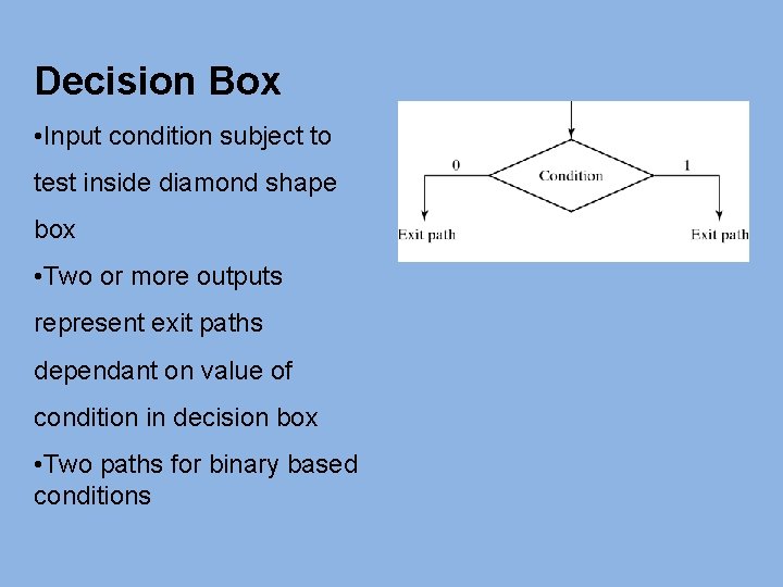
Decision Box • Input condition subject to test inside diamond shape box • Two or more outputs represent exit paths dependant on value of condition in decision box • Two paths for binary based conditions
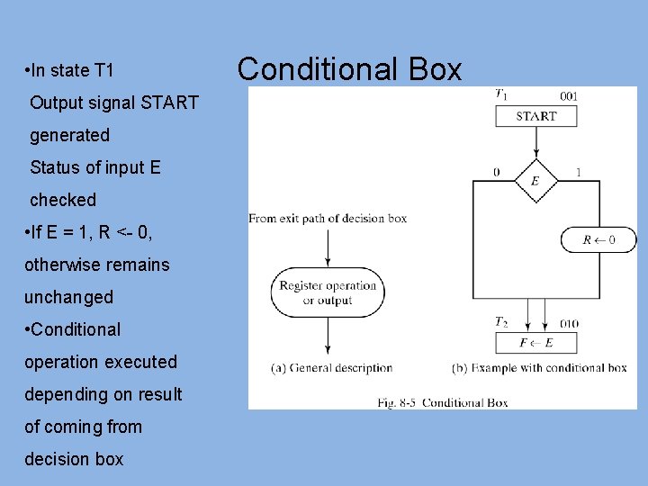
Conditional output box • Provides a listing of output variables that are to have a value logic-1, i. e. , those output variables being asserted. • Single entry from decision box. • Single exit to decision or state box.
• In state T 1 Output signal START generated Status of input E checked • If E = 1, R <- 0, otherwise remains unchanged • Conditional operation executed depending on result of coming from decision box Conditional Box
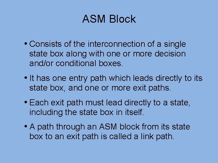
ASM Block • Consists of the interconnection of a single state box along with one or more decision and/or conditional boxes. • It has one entry path which leads directly to its state box, and one or more exit paths. • Each exit path must lead directly to a state, including the state box in itself. • A path through an ASM block from its state box to an exit path is called a link path.
Timing Considerations All sequential elements in datapath and control path controlled by master-clock generator. Does not necessarily imply single clock in design. • Multiple clocks can be obtained through division of clock signals from master-clock generator. • Not only internal signals, but also inputs synchronized with clock. • Normally, inputs supplied by other devices working with the same master clock. • Some inputs can arrive asynchronously Difficult to handle by synchronous designs, require asynchronous glue-logic.
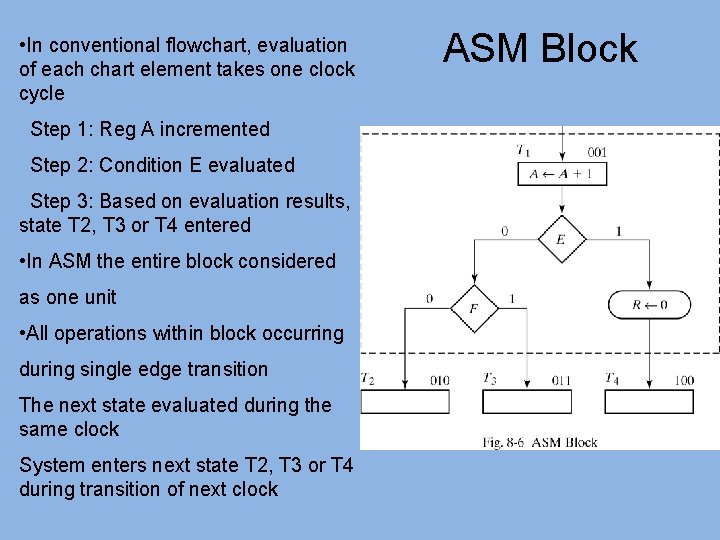
• In conventional flowchart, evaluation of each chart element takes one clock cycle Step 1: Reg A incremented Step 2: Condition E evaluated Step 3: Based on evaluation results, state T 2, T 3 or T 4 entered • In ASM the entire block considered as one unit • All operations within block occurring during single edge transition The next state evaluated during the same clock System enters next state T 2, T 3 or T 4 during transition of next clock ASM Block
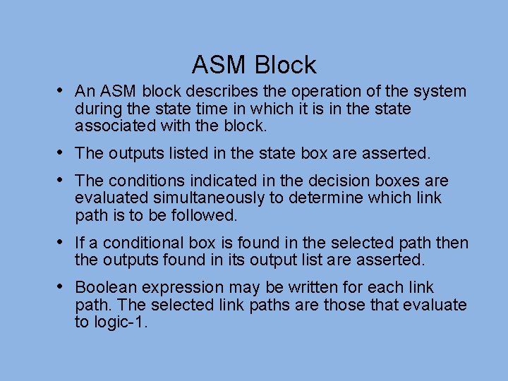
ASM Block • An ASM block describes the operation of the system during the state time in which it is in the state associated with the block. • The outputs listed in the state box are asserted. • The conditions indicated in the decision boxes are evaluated simultaneously to determine which link path is to be followed. • If a conditional box is found in the selected path then the outputs found in its output list are asserted. • Boolean expression may be written for each link path. The selected link paths are those that evaluate to logic-1.
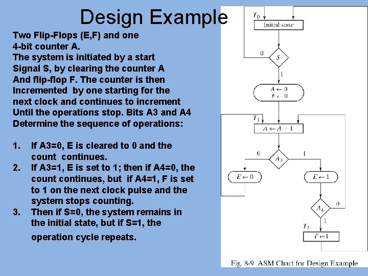
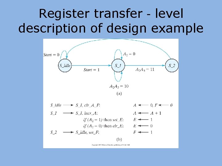
Design Example Two Flip-Flops (E, F) and one 4 -bit counter A. The system is initiated by a start Signal S, by clearing the counter A And flip-flop F. The counter is then Incremented by one starting for the next clock and continues to increment Until the operations stop. Bits A 3 and A 4 Determine the sequence of operations: 1. 2. 3. If A 3=0, E is cleared to 0 and the count continues. If A 3=1, E is set to 1; then if A 4=0, the count continues, but if A 4=1, F is set to 1 on the next clock pulse and the system stops counting. Then if S=0, the system remains in the initial state, but if S=1, the operation cycle repeats.
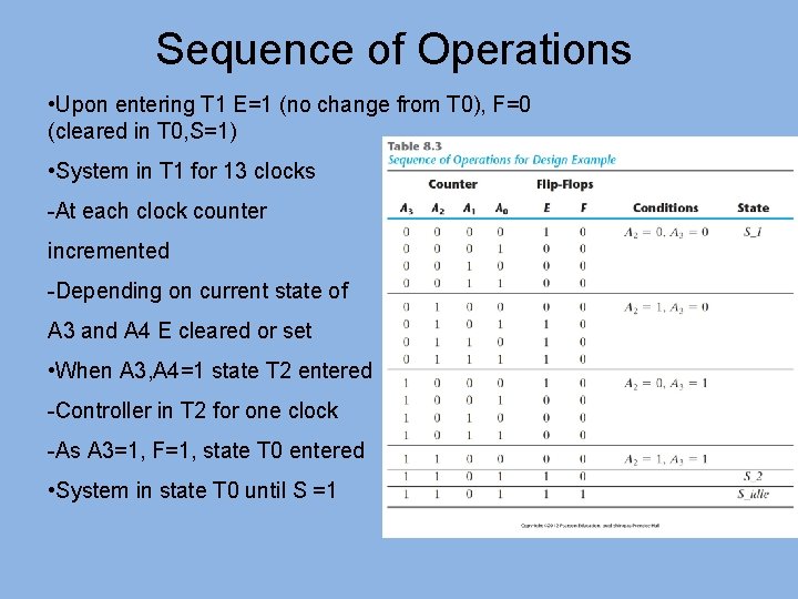
Sequence of Operations • Upon entering T 1 E=1 (no change from T 0), F=0 (cleared in T 0, S=1) • System in T 1 for 13 clocks -At each clock counter incremented -Depending on current state of A 3 and A 4 E cleared or set • When A 3, A 4=1 state T 2 entered -Controller in T 2 for one clock -As A 3=1, F=1, state T 0 entered • System in state T 0 until S =1
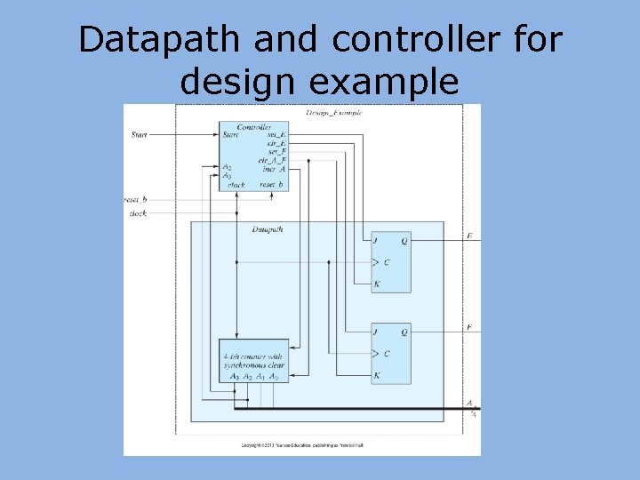
Datapath and controller for design example
Register transfer‐level description of design example
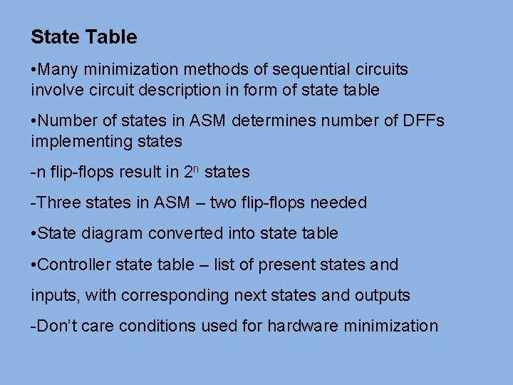
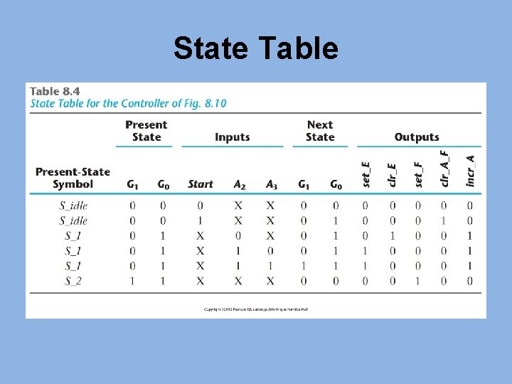
State Table • Many minimization methods of sequential circuits involve circuit description in form of state table • Number of states in ASM determines number of DFFs implementing states -n flip-flops result in 2 n states -Three states in ASM – two flip-flops needed • State diagram converted into state table • Controller state table – list of present states and inputs, with corresponding next states and outputs -Don’t care conditions used for hardware minimization
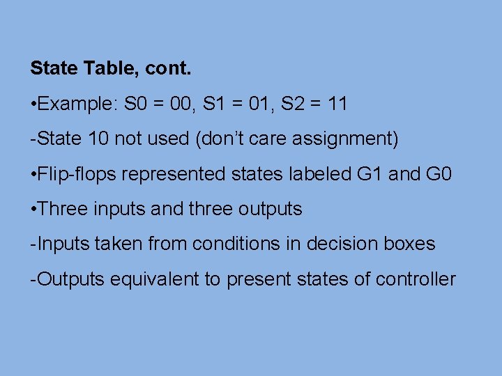
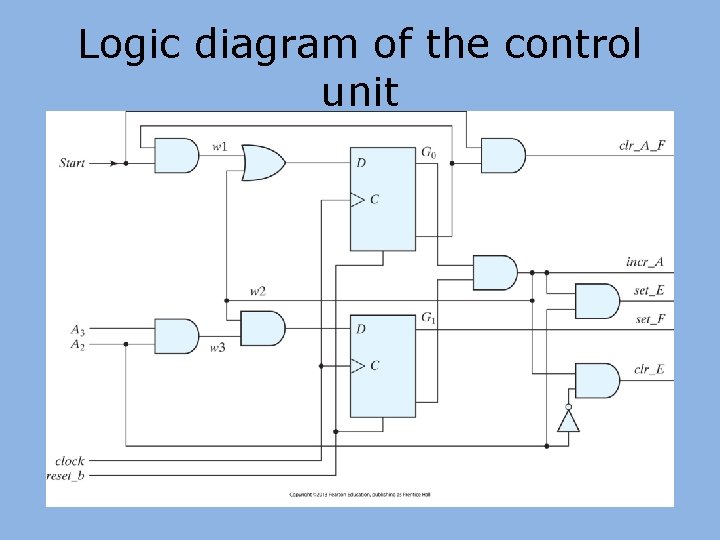
State Table, cont. • Example: S 0 = 00, S 1 = 01, S 2 = 11 -State 10 not used (don’t care assignment) • Flip-flops represented states labeled G 1 and G 0 • Three inputs and three outputs -Inputs taken from conditions in decision boxes -Outputs equivalent to present states of controller
State Table
Logic diagram of the control unit
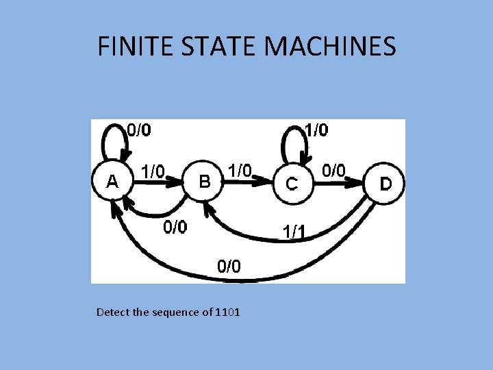
FINITE STATE MACHINES Detect the sequence of 1101
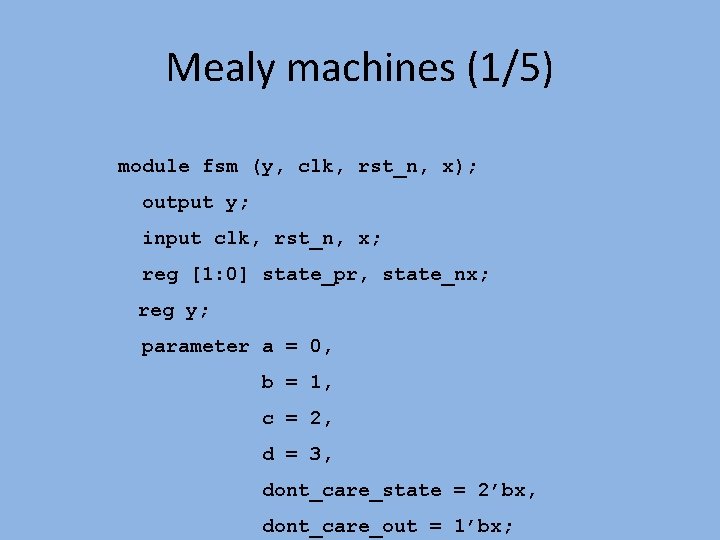
Mealy machines (1/5) module fsm (y, clk, rst_n, x); output y; input clk, rst_n, x; reg [1: 0] state_pr, state_nx; reg y; parameter a = 0, b = 1, c = 2, d = 3, dont_care_state = 2’bx, dont_care_out = 1’bx;
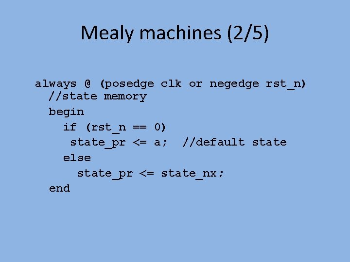
Mealy machines (2/5) always @ (posedge clk or negedge rst_n) //state memory begin if (rst_n == 0) state_pr <= a; //default state else state_pr <= state_nx; end
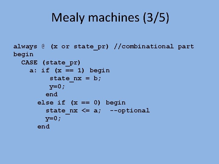
Mealy machines (3/5) always @ (x or state_pr) //combinational part begin CASE (state_pr) a: if (x == 1) begin state_nx = b; y=0; end else if (x == 0) begin state_nx <= a; --optional y=0; end
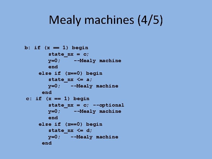
Mealy machines (4/5) b: if (x == 1) begin state_nx = c; y=0; --Mealy machine end else if (x==0) begin state_nx <= a; y=0; --Mealy machine end c: if (x == 1) begin state_nx = c; --optional y=0; --Mealy machine end else if (x==0) begin state_nx <= d; y=0; --Mealy machine end
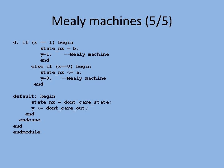
Mealy machines (5/5) d: if (x == 1) begin state_nx = b; y=1; --Mealy machine end else if (x==0) begin state_nx <= a; y=0; --Mealy machine end default: begin state_nx = dont_care_state; y <= dont_care_out; endcase endmodule