Alex Brose Tanveer Chandok and Alex Dowgwillo Introduction

* Alex Brose, Tanveer Chandok, and Alex Dowgwillo

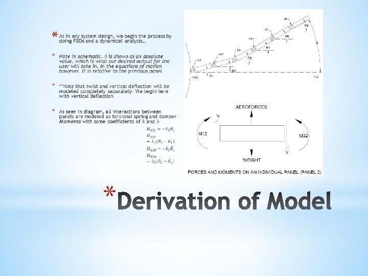
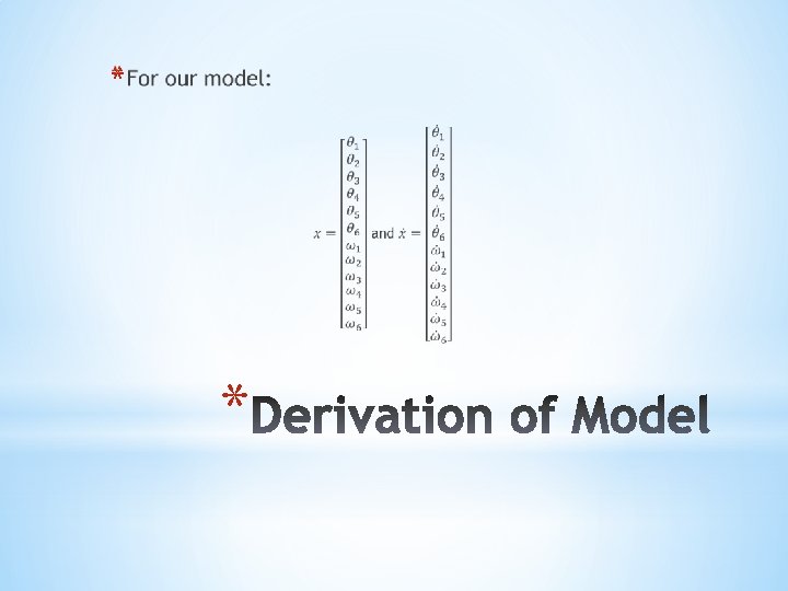
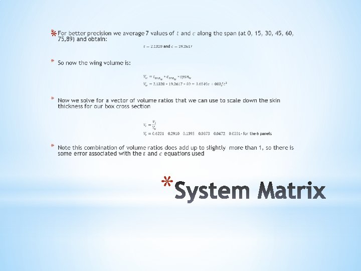
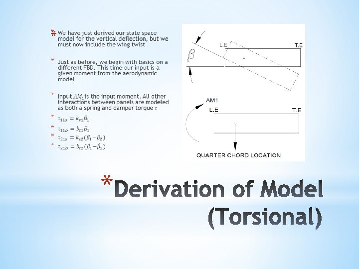
*Introduction *Design Process * Concepts and rationale * Derivation of Model and Transfer Functions *System response and implementation *

* In today’s changing world, composites are proving to be highly favorable in the building of aerospace components * This is changing the way the structure of the part affects and interacts with the aerodynamic model * In this analysis the group was tasked with analyzing the wing section of a Boeing 787 aircraft *
 methods are most favorable * Primary objective is to")
* Finite Element Analysis (FEA) methods are most favorable * Primary objective is to design a model that can describe a physical system of panels on a wing from given force inputs and output deflection * Process throughout this model’s design included the following steps: * Research * Discuss * Make simplifying assumptions * Check validity *

* After a lot of research on how to approach designing this model, decided that a state space representation would best describe and model the type of system given’s behavior * Why State Space? * System has many degrees of freedom (6 panels) * If we define the system of panels’ FBDs in a “state space manner”, we find that it meets the requirements! *


Breakpoint * *


*The model obtained is tested by using different types of input. Mainly: * Impulse input * Step Input * Sinusoidal input * Turbulent Flow * Steady State Flow *

*The system response produces the following types of outputs: * Deflection vs. Time graphs * BODE plots *

* Deflection vs. Time for an Impulse Input is applied on Panel 3 and the resulting deflections on all other panels are displayed. Note how every panel reacts differently due to the changes in the k and b values of each panel *

* 2 Impulse Inputs applied on Panel 3 and Panel 5 and 2 Impulse Inputs on the Aileron at 5 deg and 10 deg. The resultant deflections of all other panels is shown. Note: The compounding deflections across the entire wing is noticed. *

* Total tip deflection under Impulse Input on Panel 3: Notice how the system returns back to zero due to the damping effect. *

* Sinusoidal input on Panel 4. Resultant deflections of every other panel is displayed. *

* Total deflection of the tip when a Sinusoidal Input at Panel 4 is applied. *

*Deflection of each panel with a Step Input applied on Panel 5. *

* Total deflection at the tip caused due to a Step Input applied on Panel 5. *

* Deflection of all panels caused due to an Impulse Input applied on Panel 3 and a Step Input applied on Panel 5. *

* Total tip deflection caused due to an Impulse Input applied on Panel 3 and a Step Input applied on * Panel 5.

* Steady State on all panels. Aileron at zero degrees *

* Steady State aileron deflection first at 5 degrees and then at 10 degrees *

* Steady State deflection at the tip *

* Steady State deflection over the span of the wing *
 with time. * Deflection twist rate over span")
* Deflection of the wing (span) with time. * Deflection twist rate over span vs. time. Note: There is a new line drawn for every period in time. *

* Modeling these different types of input function into our system of transfer function for both deflection and twist we can predict our model’s validity in real world scenarios * Using Brad Sexton and online sources already cited, we had an idea of what damping coefficients we need, but to get realistic responses, we use the same method of “educated guess and check” for all the charts produced * Some charts like the sinusoid produced errors, but rearranging certain properties in the MATLAB code using the guess and check method proved somewhat successful *

*Introduction *Design Process * Concepts and rationale * Derivation of Model and Transfer Functions *System response and implementation *

- Slides: 62