Aircraft Structures STRUCTURE TYPES 3 commonly used types


")


 In a properly designed sheet metal joint,")

 below which")


- Slides: 37
Aircraft Structures
STRUCTURE TYPES • 3 commonly used types are: • TRUSS • SEMI-MONOCOQUE • MONOCOQUE
TRUSS • Uses triangle construction for strength • All members carry both tension and compression loads • Welded steel tube frame • Fabric covering • Wood or aluminum wing spars and ribs • Uses compression struts and drag wires
SEMI- MONOCOQUE • Most common • Stressed skin supported by framework • Skin supported by bulkheads, formers, stringers, and longerons • Both skin and framework are structural
MONOCOQUE • Designed using minimum internal structure • Skin shape and stiffness is critical to the structural integrity • Bulkheads are used for maintaining shape • Cone shaped fuselage is typical
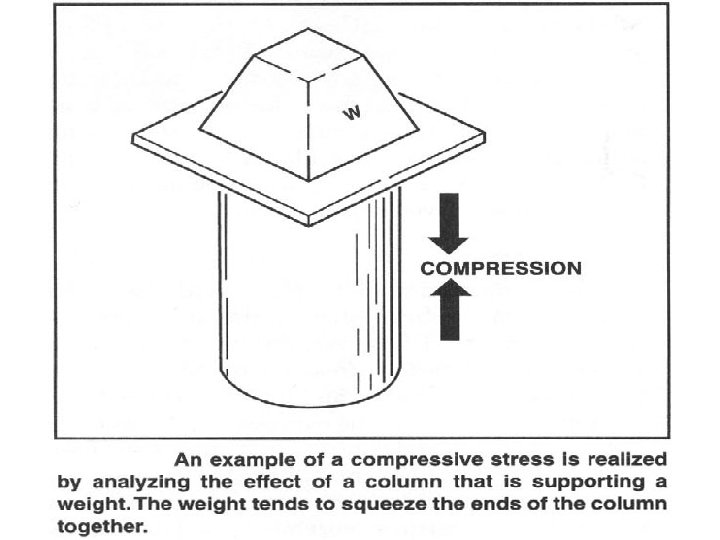
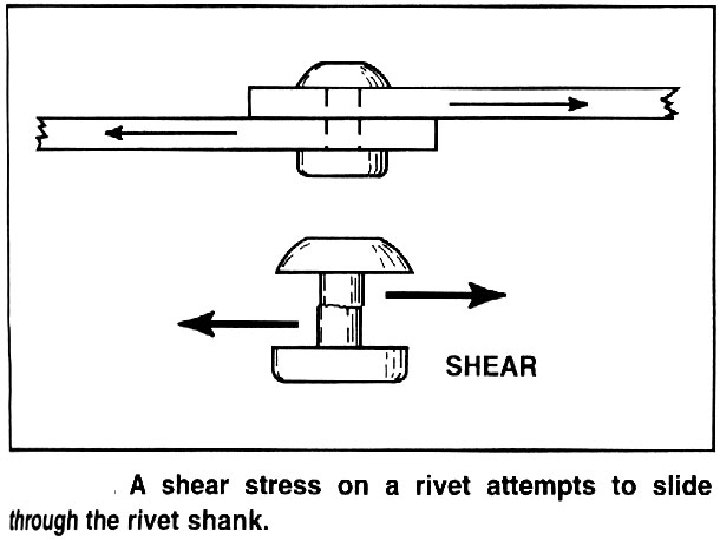
STRUCTURAL STRESS • In order to design and perform an effective repair to aircraft sheetmetal you must understand the 6 types of stresses imposed upon the airframe TENSION BENDING SHEAR COMPRESSION TORSION BEARING
( STRETCHING )
GRAVITY
IN-FLIGHT GROUNDED
TWISTING
RIVET STRENGTH • SINGLE SHEAR STRENGTH is the amount of force required to cut a rivet holding 2 or more sheets of material • If the rivet is holding 3 sheets of material its considered to be under DOUBLE SHEAR
RIVET STRENGTH • BEARING STRENGTH is the amount of tension required to pull a rivet through the edge of 2 sheets of metal riveted together • Or…… to just elongate the holes
Balance of Shear vs. Bearing strength (1) In a properly designed sheet metal joint, bearing strength and shear strength should be nearly the same as possible. (2) Shear strength is usually kept slightly less for each kind of repair.
1. Strain - deformation in material that has been caused by stress 2. Yield point - when a stress is applied, the point at which permanent deformation first takes place in material 3. Ultimate strength - (tensile strength) - the maximum load a material will stand before failure (breakage)
Fatigue limit - that amount of force in a repeating stress (cyclic) below which point the material will not permanently deform. Steel has a fatigue limit - With steel, the heavier the cyclic load, the quicker the part will fail. As the load is lightened, there is a point at which the steel part will not fail (for an indefinite period) due to fatigue. That is its fatigue limit. Aluminum has no fatigue limit - With aluminum, regardless how small the cyclic load is, it will eventually fail due to fatigue. The heavier the load the quicker it will fail, but it will always fail at some point, even though the load may be very light and the cycles tremendously high in number. Only a matter of time.
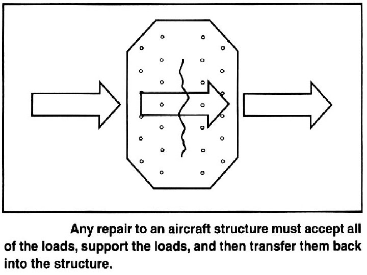
LOAD TRANSFER • Any repair must accept the stresses, carry them across the repair, and transfer them back to the original structure • Stresses must flow thru the structure with no abrupt changes in X –sectional areas that are subject to cycle loading. They must not result in concentration that induces fatigue cracking and failure. • NO SCRATCHES or GOUGES are allowed as they will concentrate stress and crack under load
REPAIR CRITERIA • Repairs must be strong enough to carry ALL of the loads plus the required safety margin (@150%)……. but not have too much extra strength or add undue weight. • Weak joints cannot be tolerated but one with too much strength will cause stress risers that tend to produce cracks in other areas
CLOSELY INSPECT TO FIND THE ACTUAL END OF THE CRACK STOP DRILL USING A # 50 BIT
MAINTAINING CONTOUR • All repairs must be made in such a manner as to ensure they will fit the original contours PERFECTLY • Smooth contour is especially desirable when repairing external skin on high speed aircraft
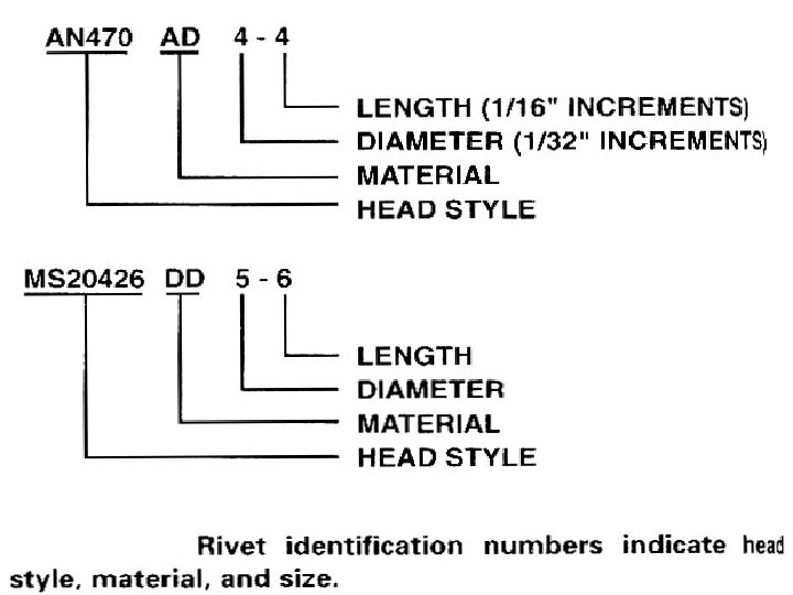
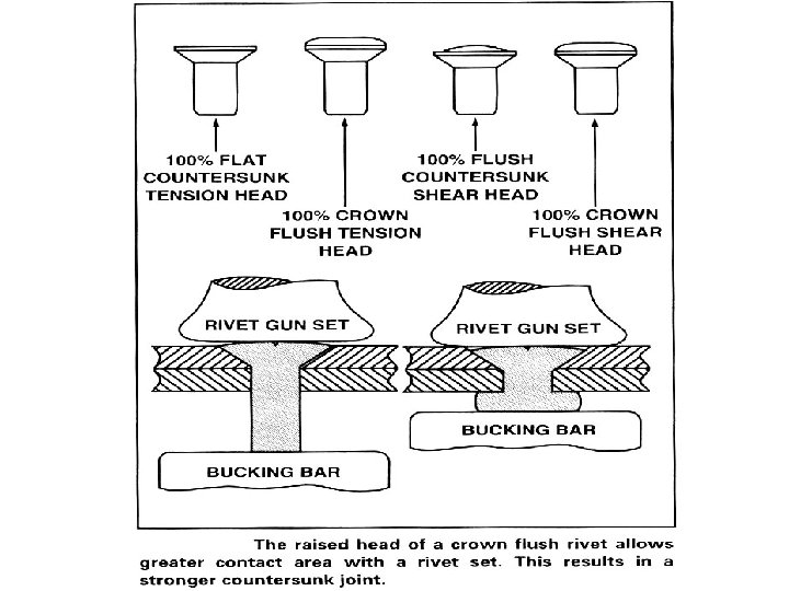
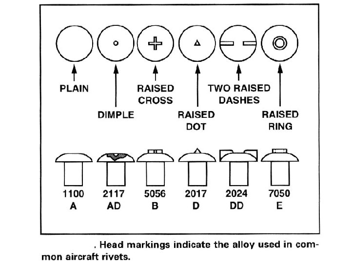
SOLID RIVETS • DESPITE THE VAST ARRAY OF SOLID RIVETS YOU’VE BEEN SHOWN, THE AD RIVET IS INDUSTRY STANDARD • THE 2117 AD RIVET IS DRIVEN IN THE AS RECEIVED CONDITION WITH NO HEAT TREATMENT REQUIRED • THERE ARE INSTANCES WHERE AN 1100 SOFT RIVET IS ADEQUATE AND REQUIRED • 2 COMMON TYPES OF AVIATION RIVETS ARE SOLID AND BLIND
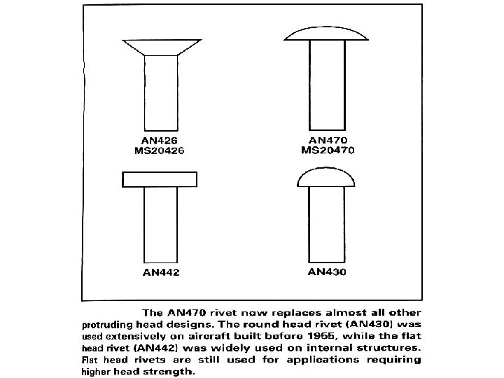
SOLID RIVETS • THE 100 DEGREE CTR SUNK AD RIVET HAS ALSO BECOME STANDARD • REPLACEMENT RIVETS MUST BE OF THE SAME STRENGTH AND SIZE AS THOSE BEING REPLACED • NEXT LARGER SIZE IS AUTHORIZED BY AC 43. 13 WHEN THE RIVET HOLE HAS BECOME ENLARGED AND THE CORRECT SIZE RIVET CANNOT BE PROPERLY SET • SOLID RIVETS ARE AVAILABLE IN ½ SIZES BUT ARE GENERALLY CUT FROM A LONGER RIVET TO PERFECTLY FIT
BUCKING BAR SELECTION • WHICH BAR YOU USE WILL BECOME A PERSONAL DECISION WITH INCREASED EXPERIANCE. • THE WEIGHT OF THE BAR SHOULD MATCH THE RIVET SIZE AND THE POWER OF THE HIT FROM THE GUN • AD 3 RIVETS WILL REQUIRE A LIGHTER WEIGHT BAR THAN AD 4 OR AD 5’s • BAR SHAPE WILL BE DETERMINED BY AREA AND COMPONENTS BEING REPAIRED