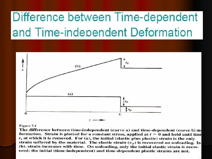
AIRCRAFT MATERIALS AND PROCESSES AERONAUTICAL ENGINEERING MATERIAL Material


 • Cubic unit cell is 3 D repeat unit •")
 • Coordination # = 8 (Courtesy P. M. Anderson)")
 • Coordination # = 12 (Courtesy P. M. Anderson)")
 Ideally, c/a = 1. 633 for close packing However, in")


 n Essentially")


 grain boundaries,")


 is the process of making")


- Slides: 120
AIRCRAFT MATERIALS AND PROCESSES AERONAUTICAL ENGINEERING
MATERIAL Ø Material is synonymous with substance, and is anything made of matter – hydrogen, air and water are all examples of materials Ø The basis of materials science involves relating the desired properties and relative performance of a material in a certain application to the structure of the atoms and phases in that material through characterization. Ø The major determinants of the structure of a material and thus of its properties are its constituent chemical elements and the way in which it has been processed into its final form. Ø The manufacture of a perfect crystal of a material is currently physically impossible. Instead materials scientists manipulate the defects in crystalline materials such as precipitates, grain boundaries, interstitial atoms, vacancies or substitutional atoms, to create materials with the desired properties.
CRYSTALLOGRAPHY What is a crystal? Ø In materials science a crystal is a solid substance in which the atoms, molecules or ions are arranged in an orderly repeating pattern extending in all three spatial dimensions - length, width and height. The process of forming a crystalline structure from a fluid or from materials dissolved in the fluid is often referred to as crystallization. Ø Various types of crystal structures in interest Ø 1. 2. 3. 4. SC BCC FCC HCP
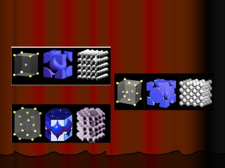
SIMPLE CUBIC STRUCTURE (SC) • Cubic unit cell is 3 D repeat unit • Rare (only Po has this structure) • Close-packed directions (directions along which atoms touch each other) are cube edges. (Courtesy P. M. Anderson)
BODY CENTERED CUBIC STRUCTURE (BCC) • Coordination # = 8 (Courtesy P. M. Anderson) Adapted from Fig. 3. 2, Callister 6 e. • Close packed directions are cube diagonals. --Note: All atoms are identical; the center atom is shaded differently only for ease of viewing.
FACE CENTERED CUBIC STRUCTURE (FCC) • Coordination # = 12 (Courtesy P. M. Anderson) Adapted from Fig. 3. 1(a), Callister 6 e. • Close packed directions are face diagonals. --Note: All atoms are identical; the face-centered atoms are shaded differently only for ease of viewing.
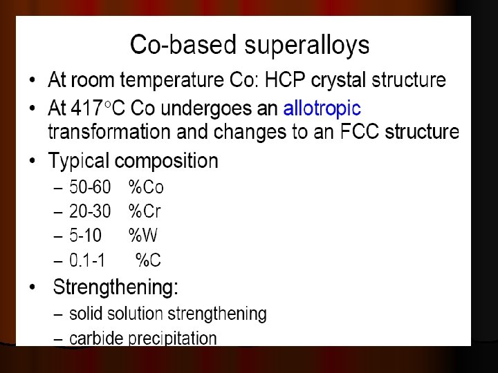
HEXAGONAL CLOSE-PACKED STRUCTURE (HCP) Ideally, c/a = 1. 633 for close packing However, in most metals, c/a ratio deviates from this value
Some metals & their crystal structures
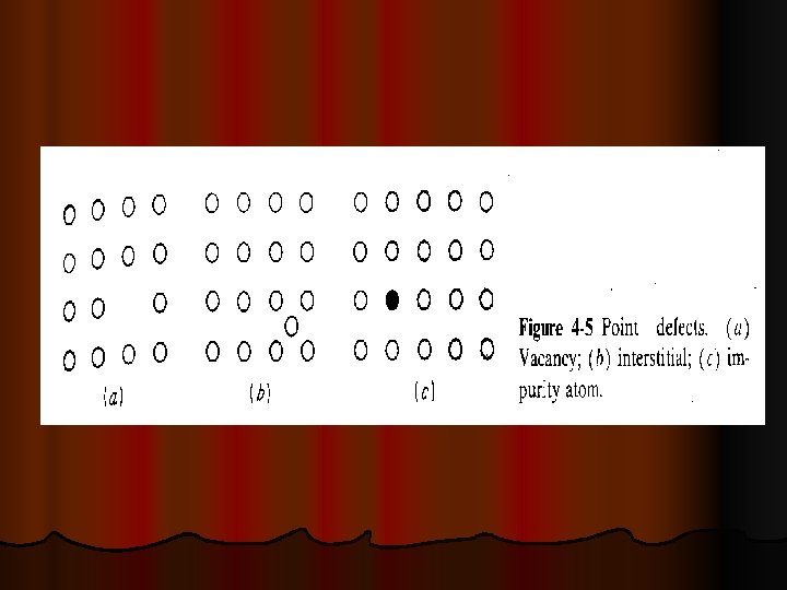
CRYSTAL DEFECTS A perfect crystal, with every atom of the same type in the correct position, does not exist. All crystals have some defects. Defects contribute to the mechanical properties of metals l There are basic classes of crystal defects: l Point defects, which are places where an atom is missing or irregularly placed in the lattice structure. Point defects include lattice vacancies, self-interstitial atoms, substitution impurity atoms, and interstitial impurity atoms Ø Linear defects, which are groups of atoms in irregular positions. Linear defects are commonly called dislocations. Ø Planar defects, which are interfaces between homogeneous regions of the material. Planar defects include grain boundaries, stacking faults and external surfaces. Ø
POINT DEFECTS Ø Ø Ø A self interstitial atom is an extra atom that has crowded its way into an interstitial void in the crystal structure. A substitutional impurity atom is an atom of a different type than the bulk atoms, which has replaced one of the bulk atoms in the lattice. Substitutional impurity atoms are usually close in size (within approximately 15%) to the bulk atom. An example of substitutional impurity atoms is the zinc atoms in brass. In brass, zinc atoms with a radius of 0. 133 nm have replaced some of the copper atoms, which have a radius of 0. 128 nm. Interstitial impurity atoms are much smaller than the atoms in the bulk matrix. Interstitial impurity atoms fit into the open space between the bulk atoms of the lattice structure. An example of interstitial impurity atoms is the carbon atoms that are added to iron to make steel. Carbon atoms, with a radius of 0. 071 nm, fit nicely in the open spaces between the larger (0. 124 nm) iron atoms. Vacancies are empty spaces where an atom should be, but is missing. They are common, especially at high temperatures when atoms are frequently and randomly change their positions leaving behind empty lattice sites. In most cases diffusion (mass transport by atomic motion) can only occur because of vacancies
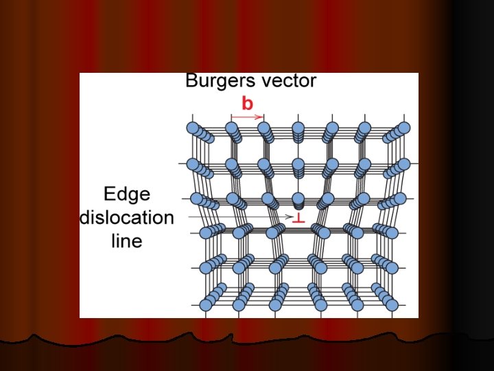
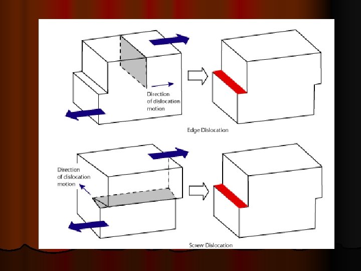
LINEAR DEFECTS Dislocations are another type of defect in crystals. Dislocations areas were the atoms are out of position in the crystal structure. Dislocations are generated and move when a stress is applied. The motion of dislocations allows slip – plastic deformation to occur. Ø In the early 1900’s scientists estimated that metals undergo plastic deformation at forces much smaller than theoretical strength of the forces that are holding the metal atoms together. Ø There are two basic types of dislocations, Ø ü ü the edge dislocation the screw dislocation. EDGE DISLOCATIONS The edge defect can be easily visualized as an extra half-plane of atoms in a lattice. Ø The dislocation is called a line defect because the locus of defective points produced in the lattice by the dislocation lie along a line. Ø This line runs along the top of the extra half-plane. Ø The inter-atomic bonds are significantly distorted only in the immediate vicinity of the dislocation line. Ø Ø Dislocation motion is analogous to movement of a caterpillar
SCREW DISLOCATIONS The motion of a screw dislocation is also a result of shear stress, but the defect line movement is perpendicular to direction of the stress and the atom displacement, rather than parallel. Ø The image aside shows the screw dislocation Ø
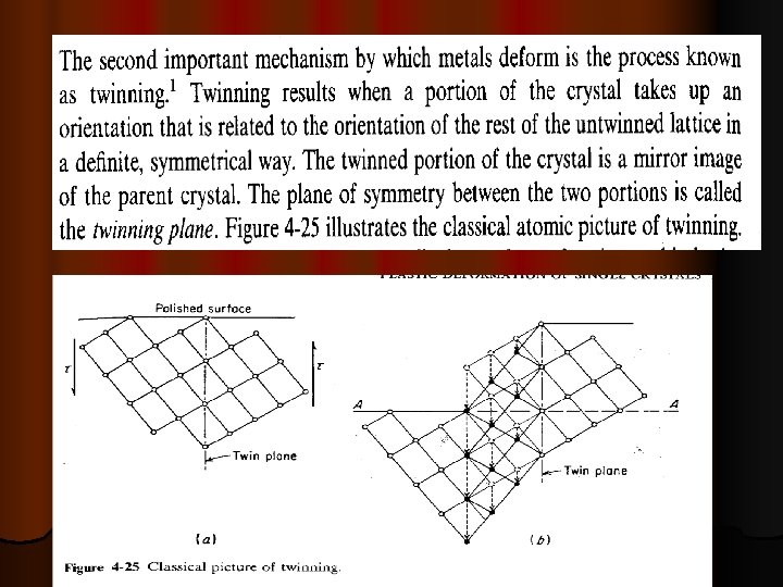
Planar Defects in Solids n One case is a twin boundary (plane) n Essentially a reflection of atom positions across the twin plane. Adapted from Fig. 5. 14, Callister & Rethwisch 3 e. n Stacking faults n n For FCC metals an error in ABCABC packing sequence Ex: ABCABABC 16
GRAIN BOUNDARY CONCEPT l l l If you were to take a small section of a common metal and examine it under a microscope, you would see a structure similar to that shown in figure. Each of the light areas is called a grain, or crystal, which is the region of space occupied by a continuous crystal lattice. The dark lines surrounding the grains are grain boundaries. The grain structure refers to the arrangement of the grains in a metal, with a grain having a particular crystal structure. The grain boundary refers to the outside area of a grain that separates it from the other grains. The grain boundary is a region of misfit between the grains and is usually one to three atom diameters wide. A very important feature of a metal is the average size of the grain. The size of the grain determines the properties of the metal. For example, smaller grain size increases tensile strength and tends to increase ductility. A larger grain size is preferred for improved hightemperature creep properties.
Some of the more important physical and chemical properties from an engineering material standpoint will be discussed in the following sections. Ø Phase Transformation Temperatures Ø Density Ø Specific Gravity Ø Thermal Conductivity Ø Linear Coefficient of Thermal Expansion Ø Electrical Conductivity and Resistivity Ø Magnetic Permeability Ø Corrosion Resistance
l You should be familiar with the following terms which you would have studied in lower classes. Engineering stress 2. Engineering strain 3. True stress 4. True strain 5. Yield strength 6. Yield point 7. Ultimate point And some basic definitions related to strength of materials 1.
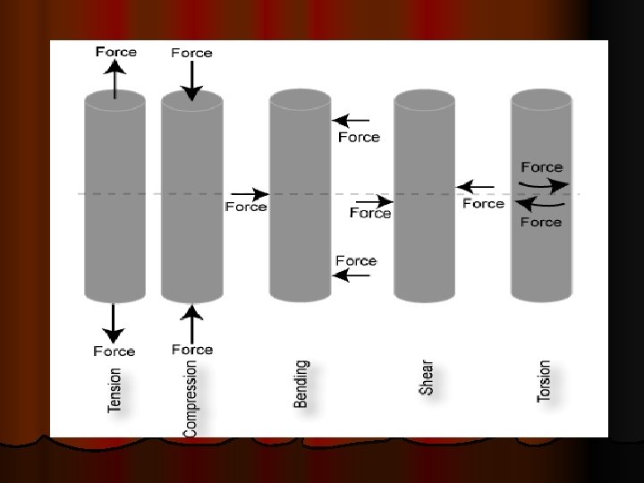
What is meant by loading a material? Ø Ø Ø Ø The application of a force to an object is known as loading. Materials can be subjected to many different loading scenarios and a material’s performance is dependant on the loading conditions. There are five fundamental loading conditions; tension, compression, bending, shear, and torsion. Tension is the type of loading in which the two sections of material on either side of a plane tend to be pulled apart or elongated. Compression is the reverse of tensile loading and involves pressing the material together. Loading by bending involves applying a load in a manner that causes a material to curve and results in compressing the material on one side and stretching it on the other. Shear involves applying a load parallel to a plane which caused the material on one side of the plane to want to slide across the material on the other side of the plane. Torsion is the application of a force that causes twisting in a material. If a material is subjected to a constant force, it is called static loading. If the loading of the material is not constant but instead fluctuates, it is called dynamic or cyclic loading. The way a material is loaded greatly affects its mechanical properties and largely determines how, or if, a component will fail; and whether it will show warning signs before failure actually occurs.
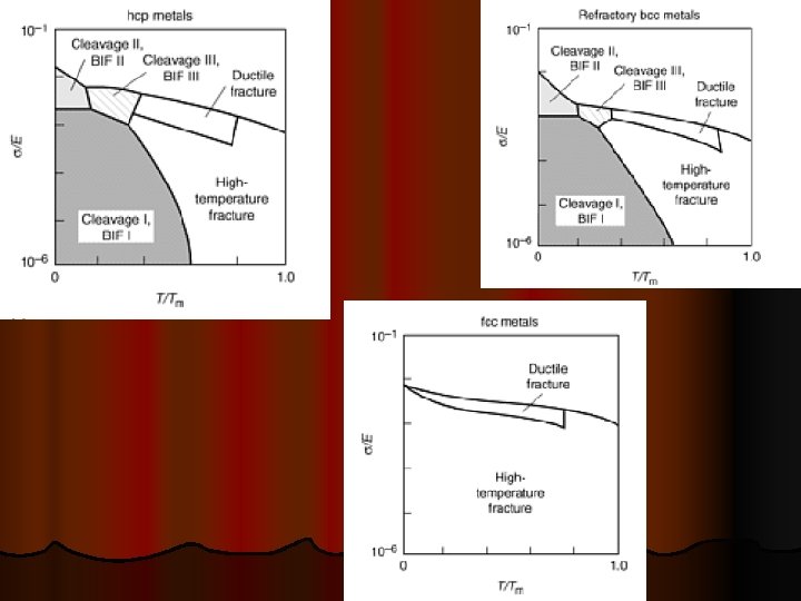
PROBLEMS FACED BY MATERIALS OPERATED AT ELEVATED TEMPERATURES
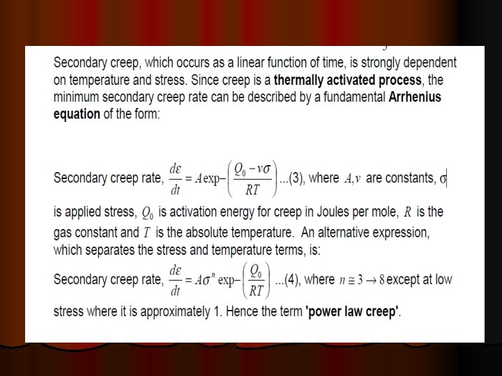
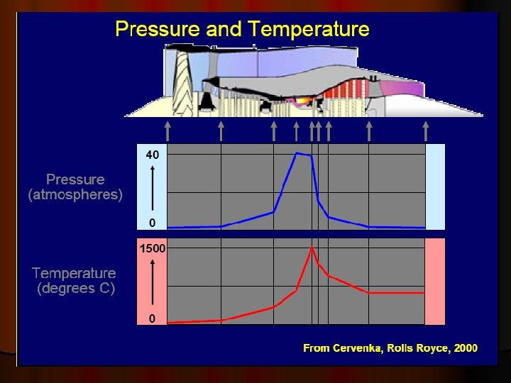
The mechanical strength of metals decreases with increasing temperature and the properties become much more time dependent. Ø In the past the operating temperatures in applications like steam power plant, chemical plant and oil refineries seldom exceeded 500 o. C, but since the development of the gas turbine in the 1940's successive designs have pushed this temperature up to typically 1000 o. C. Ø Developments in high temperature alloys with improved high temperature strength and oxidation resistance have had to keep pace with these demands, and applications like rocket engines present greater problems. Ø Ø At homologous temperatures of more than 0. 5, creep is of engineering significance
HIGH TEMPERATURE >0. 3 TM ØCreep ØHigh temperature fracture ØCorrosion ØFatigue ØEmbrittlement These are the factors affecting the functional or service life of components at elevated temperatures
CREEP
CREEP Ø Creep is the tendency of a solid material to slowly move or deform permanently under the influence of stresses. Ø It occurs as a result of long term exposure to levels of stress that are below the yield strength of the material. Creep is more severe in materials that are subjected to heat for long periods, and near the melting point. Creep always increases with temperature. The rate of this deformation is a function of the material properties, exposure time, exposure temperature and the applied structural load. The temperature range in which creep deformation may occur differs in various materials. the effects of creep deformation generally become noticeable at approximately 30% of the melting point for metals and 40– 50% of melting point for ceramic Creep deformation is important not only in systems where high temperatures are endured such as nuclear power plants, jet engines and heat exchangers In steam turbine power plants, pipes carry steam at high temperatures (566 °C or 1050 °F) and pressures (above 24. 1 MPa or 3500 psi). In jet engines, temperatures can reach up to 1400 °C (2550 °F) and initiate creep deformation in even advanced-coated turbine blades. Hence, it is crucial for correct functionality to understand the creep deformation behavior of materials. Ø Ø Ø
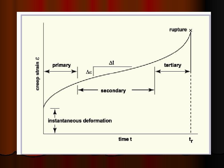
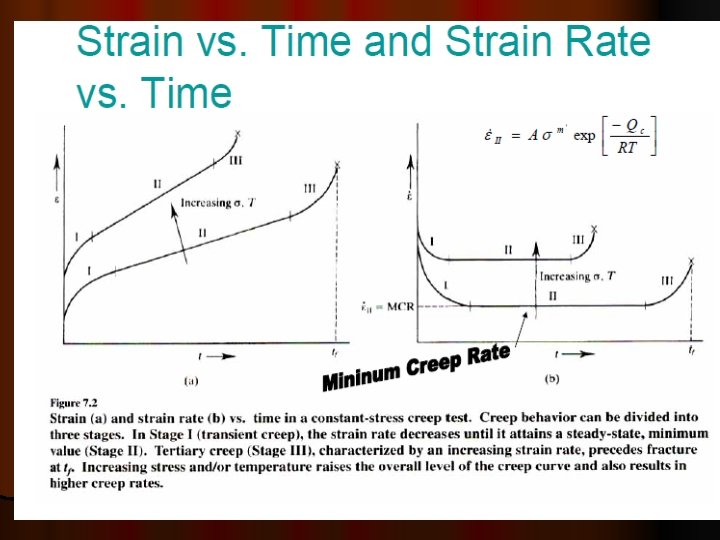
Ø Ø Ø Creep data for general design use are usually obtained under conditions of constant uniaxial loading and constant temperature. Results of tests are usually plotted as strain versus time up to rupture. As indicated in the image, creep often takes place in three stages. In the initial stage, strain occurs at a relatively rapid rate but the rate gradually decreases until it becomes approximately constant during the second stage. This constant creep rate is called the minimum creep rate or steadystate creep rate since it is the slowest creep rate during the test. In the third stage, the strain rate increases until failure occurs. Creep in service is usually affected by changing conditions of loading and temperature and the number of possible stresstemperature-time combinations is infinite. While most materials are subject to creep, the creep mechanisms is often different between metals, plastics, rubber, concrete. High homologous temperatures (Tservice/Tmelting) Unlike brittle fracture, creep deformation does not occur suddenly upon the application of stress. Instead, strain accumulates as a result of long-term stress. Creep deformation is "time-dependent" deformation.
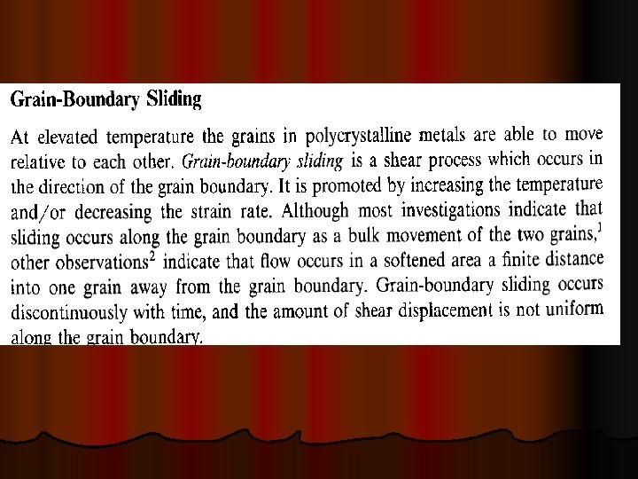
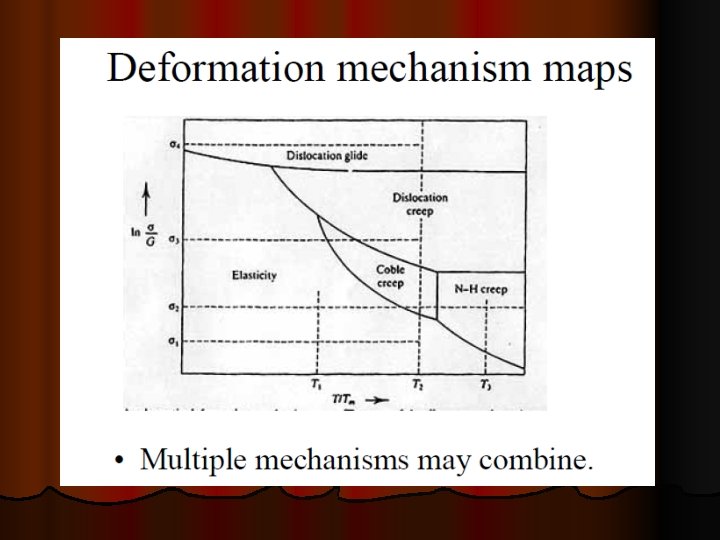
MECHANISMS OF CREEP IN METALS There are three basic mechanisms that can contribute to creep in metals, namely: (i) Dislocation slip and climb. (ii) Grain boundary sliding. (iii) Diffusional flow
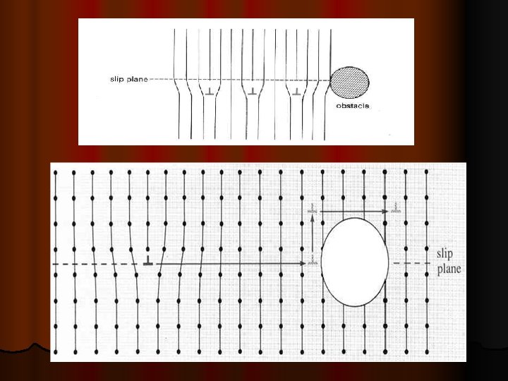
DISLOCATION CREEP l Dislocations slip is hindered by obstacles such Ø (i) grain boundaries, Ø(ii) impurity particles, Ø(iii) the stress field around solute atoms in solution or Ø(iv) the strain fields of other dislocations.
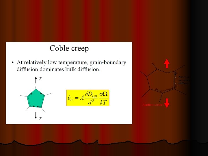
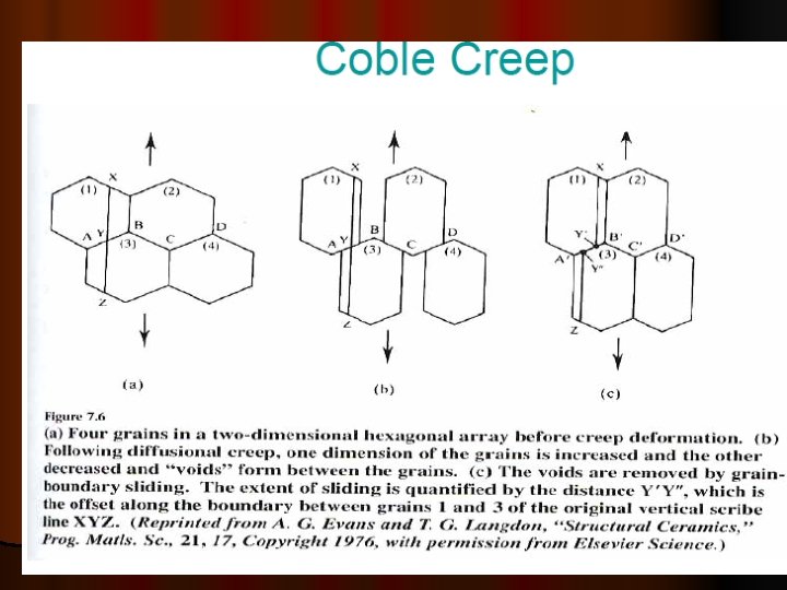
DIFFUSIONAL CREEP
GRAIN BOUNDARY SLIDING The onset of tertiary creep is a sign that structural damage has occurred in an alloy. Ø Rounded and wedge shaped voids are seen mainly at the grain boundaries and when these coalesce creep rupture occurs. Ø The mechanism of void formation involves grain boundary sliding which occurs under the action of shear stresses acting on the boundaries Ø
Voids in creep ruptured Nimonic 80 A. Showing scratch lines displaced across a grain boundary in Aluminium.
A model for the formation of cracks due to grain boundary sliding The formation of wedge cracks during grain boundary sliding.
DATA EXTRAPOLATION METHODS
LARSEN MILLER PARAMETER
AN EXAMPLE
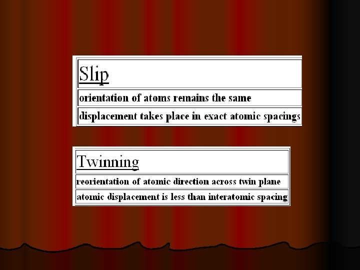
STRAIN HARDENING Strain hardening (also called work-hardening or cold-working) is the process of making a metal harder and stronger through plastic deformation. Ø When a metal is plastically deformed, dislocations move and additional dislocations are generated. The more dislocations within a material, the more they will interact and become pinned or tangled. This will result in a decrease in the mobility of the dislocations and a strengthening of the material. This type of strengthening is commonly called cold-working. It is called cold-working because the plastic deformation must occurs at a temperature low enough that atoms cannot rearrange themselves. Ø When a metal is worked at higher temperatures (hot-working) the dislocations can rearrange and little strengthening is achieved. Ø Strain hardening can be easily demonstrated with piece of wire or a paper clip. Bend a straight section back and forth several times. It increases the strength of the wire. This is said to be strain hardened wire. Ø
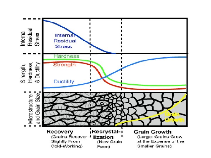
Effects of Elevated Temperature on Strain Hardened Materials When strain hardened materials are exposed to elevated temperatures, the strengthening that resulted from the plastic deformation can be lost. This can be a bad thing if the strengthening is needed to support a load. Ø Heat treatment can be used to remove the effects of strain hardening. Three things can occur during heat treatment ü Recovery ü Recrystallization ü Grain growth Ø
RECOVERY When a stain hardened material is held at an elevated temperature an increase in atomic diffusion occurs that relieves some of the internal strain energy. Ø Remember that atoms are not fixed in position but can move around when they have enough energy to break their bonds. Ø Diffusion increases rapidly with rising temperature and this allows atoms in severely strained regions to move to unstrained positions. In other words, atoms are freer to move around and recover a normal position in the lattice structure. This is known as the recovery phase and it results in an adjustment of strain on a microscopic scale. Ø Internal residual stresses are lowered due to a reduction in the dislocation density and a movement of dislocation to lower-energy positions. The tangles of dislocations condense into sharp two-dimensional boundaries and the dislocation density within these areas decrease. These areas are called sub grains. There is no appreciable reduction in the strength and hardness of the material but corrosion resistance often improves. Ø
RECRYSTALLIZATION At a higher temperature, new, strain-free grains nucleate and grow inside the old distorted grains and at the grain boundaries. These new grains grow to replace the deformed grains produced by the strain hardening. With recrystallization, the mechanical properties return to their original weaker and more ductile states. Ø Recrystallization depends on the temperature, the amount of time at this temperature and also the amount of strain hardening that the material experienced. Ø The more strain hardening, the lower the temperature will be at which recrystallization occurs. Also, a minimum amount (typically 2 -20%) of cold work is necessary for any amount of recrystallization to occur. The size the new grains is also partially dependant on the amount of strain hardening. The greater the stain hardening, the more nuclei for the new grains, and the resulting grain size will be smaller (at least initially). Ø GRAIN GROWTH If a specimen is left at the high temperature beyond the time needed for complete recrystallization, the grains begin to grow in size. This occurs because diffusion occurs across the grain boundaries and larger grains have less grain boundary surface area per unit of volume. Ø Therefore, the larger grains lose fewer atoms and grow at the expense of the smaller grains. Larger grains will reduce the strength and toughness of the material. Ø
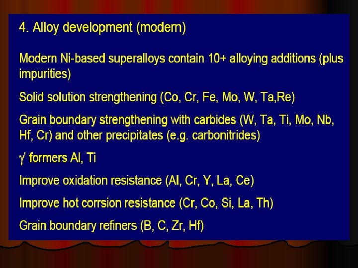
SOLID SOLUTION STRENGTHENING Solid solution strengthening is a type of alloying that can be used to improve the strength of a pure metal. The technique works by adding atoms of one element (the alloying element) to the crystalline lattice another element (the base metal). The alloying element diffuses into the matrix, forming a solid solution Ø Depending on the size of the alloying element, Ø Substitutional solid solution or Ø Intersitial solid solution Ø Substitutional solid solution strengthening occurs when the solute atom is large enough that it can replace solvent atoms in their lattice positions. According to the Hume-Rothery rules, solvent and solute atoms must differ in atomic size by less than 15% in order to form this type of solution. Ø When the solute atom is much smaller than the solvent atoms, an interstitial solid solution forms. This typically occurs when the solute atoms are less than half as small as the solvent atoms. The smaller solute atom essentially "crowds" into the spacings within the lattice structure, causing defects in the material. Elements commonly used to form interstitial solid solutions include H, N, C, and O. Carbon in iron (steel) is one example of interstitial diffusion. Ø
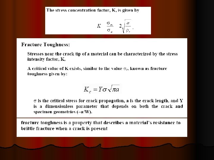
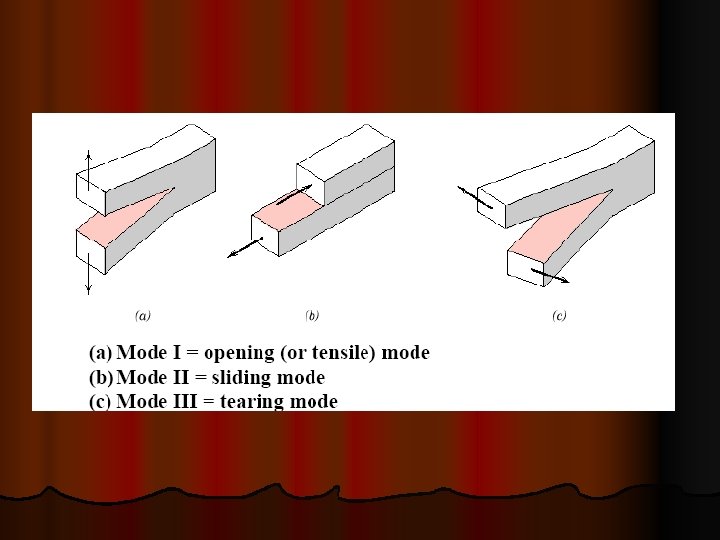
FRACTURE
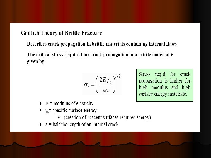
FRACTURE A separation of an object into two or more pieces in response to active stresses below the melting temperature of the material. Ø Two steps in the process of fracture: Ø Crack initiation Ø Crack propagation Ø
Types of Failure in Materials FIGURE 3. 20 Schematic illustration of types of failure in materials: (a) necking and fracture of ductile materials; (b) buckling of ductile materials under a compressive load; (c) fracture of brittle materials in compression; (d) cracking on the barreled surface of ductile materials in compression. (See also Fig. 6. 1 b) FIGURE 3. 21 Schematic illustration of the types of fracture in tension: (a) brittle fracture in polycrystalline metals; (b) shear fracture in ductile single crystals (see also Fig. 3. 4 a); (c) ductile cup-and-cone fracture in polycrystalline metals (see also Fig. 2. 2 ); (d) complete ductile fracture in polycrystalline metals, with 100% reduction of area.
DUCTILE AND BRITTLE FRACTURE
Ductile Fracture
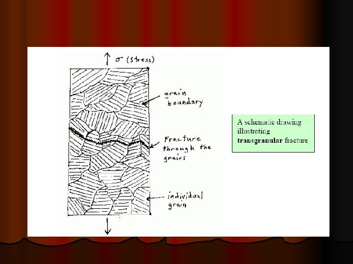
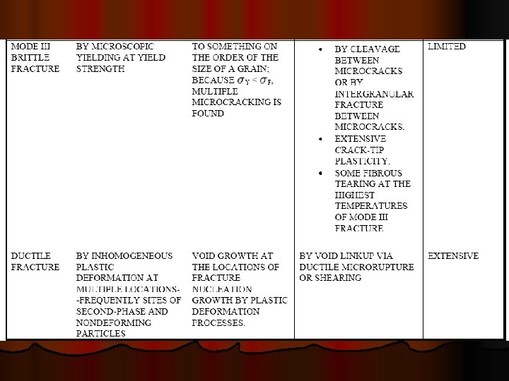
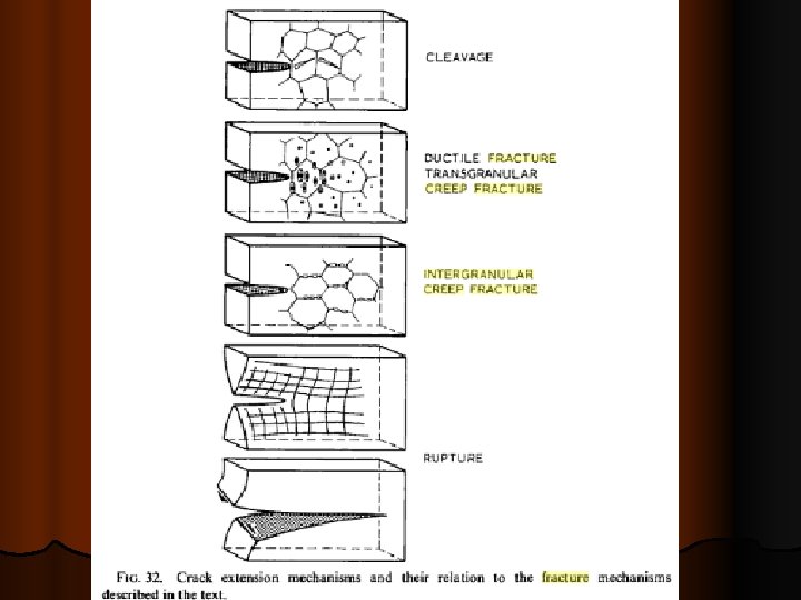
TRANSGRANULAR CREEP FRACTURE
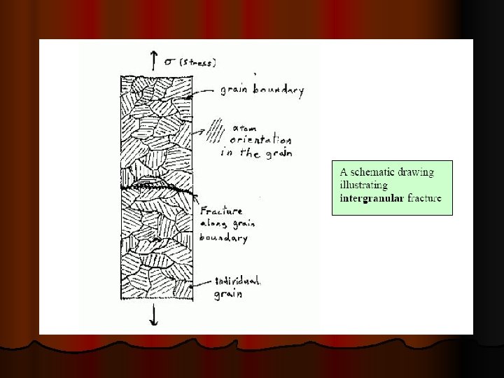
INTERGRANULAR CREEP FRACTURE
PURE DIFFUSIONAL FRACTURE
RUPTURE
HIGH TEMPERATURE CORROSION
BASICS CORROSION is the deterioration of a material by its reaction with the surroundings. It adversely affects those properties that are to be preserved. At higher temperature, this mode of degradation is known as oxidation or dry corrosion or scaling. Metals and alloys sometimes experience accelerated oxidation when their surfaces are covered with a thin film of fused salt in an oxidizing atmosphere at elevated temperatures. This mode of attack is called ‘hot corrosion’, where a porous, non-protective oxide scale is formed at the surface and sulphides in the substrate High temperature corrosion is a form of corrosion that does not require the presence of a liquid electrolyte. In general, the names of the corrosion mechanisms are determined by the most abundant dominant corrosion products. For example: Ø Ø Oxidation implies oxides, Sulfidation implies sulfides, Sulfidation/oxidation implies sulfides plus oxides, and Carburization implies carbides
High temperature corrosion is a widespread problem in various industries such as: Ø power generation (nuclear and fossil fuel) Ø aerospace and gas turbine Ø heat treating Ø mineral and metallurgical processing Ø chemical processing Ø refining and petrochemical Ø automotive Ø pulp and paper Ø waste incineration
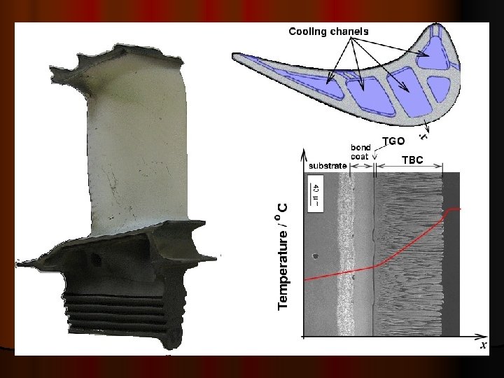
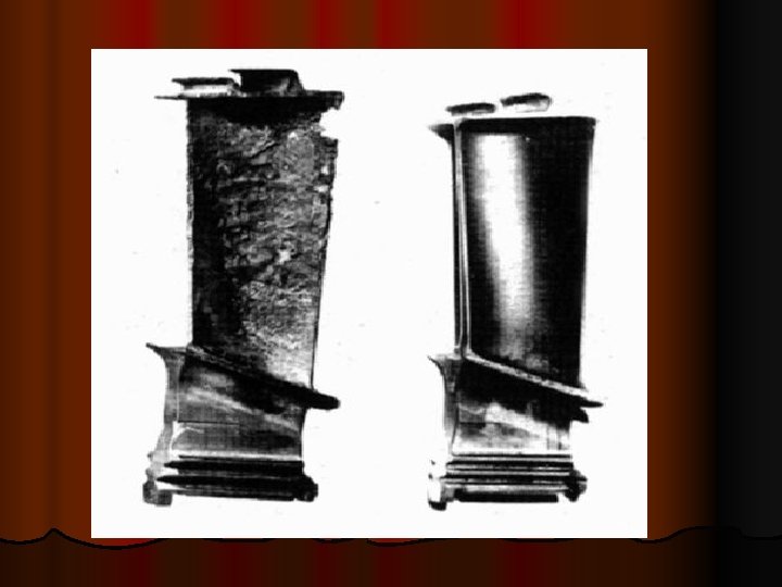
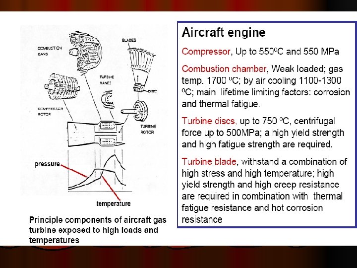
During operation, blades and vanes of gas turbines are subjected to high thermal stresses and mechanical loads. In addition, they are also attacked chemically by oxidation and/or high-temperature corrosion. Only composite materials are able to meet such a demanding spectrum of requirements; the base material provides the necessary mechanical properties and coatings provide protection against oxidation and corrosion
Hot corrosion may be defined as an accelerated corrosion, resulting from the presence of salt contaminants such as Na 2 SO 4, Na. Cl, and V 2 O 5 that combine to form molten deposits, which damage the protective surface oxides Hot corrosion occurs when metals are heated in the temperature range 700– 900°C in the presence of sulphate deposits formed as a result of the reaction between sodium chloride and sulphur compounds in the gas phase surrounding the metals. At higher temperatures, deposits of Na 2 SO 4 are molten (m. p. 884°C) and can cause accelerated attack on Ni- and Co-based superalloys. This type of attack is commonly called ‘hot corrosion’. Accelerated corrosion can also be caused by other salts, viz. vanadates or sulphates– vanadate mixtures and in the presence of solid or gaseous salts such as chlorides
CHARACTERISTICS AND MECHANISM OF HOT CORROSION Hot corrosion can occur at high temperatures, where the deposit is in the liquid state right from the beginning, or the solid deposit turns into liquid during exposure as a result of reaction with the environment. These two types of hot corrosion processes are termed as Ø High Temperature Hot Corrosion (HTHC) or Type I Ø Low Temperature Hot Corrosion (LTHC) or Type II respectively
TYPES OF OXIDE LAYERS High temperature oxidation usually results in formation of an oxide layer on the surface of the oxidizing metal. Thin oxide layers (commonly thinner than 3000 Å) are called films. Thicker oxide layers (above 3000 Å) are called scales. (1. 0 Å = 10 -10 m) Oxide scale may be composed of several layers of different oxides. At the temperatures above 1050ºF (566ºC) iron scale consists of three layers: Fe. O (the layer adjacent to iron), Fe 3 O 4 (middle layer) and Fe 2 O 3 (surface layer). Ø Depending on their structures, the scales may be categorized into two groups: protective scales and non-protective scales. Protective scale prevents access of oxygen to the metal surface due to non-porous continuous structure of the oxide layer. Ø Non-protective scale has loose porous structure providing free access of oxygen to the underlaying metal. Ø
Ø The scales type may be determined by the Pilling- Bedworth rule: Ø The scale is protective (adherent and non-porous) if the volume of the oxide is not less than the volume of metal, from which the oxide was formed. Ø The scale is non-protective (porous) if the volume of the oxide is less than the volume of metal, from which the oxide was formed. Ø Oxides with volume much greater (twice and more) than the volume of metal, from which the oxide was formed cause developing compressive stresses. The stresses may lead to cracking and spalling of the scale, which result in faster penetration of oxygen to the metal surface.
Protective oxides Be 1. 59 Cu 1. 68 Al 1. 28 Cr 1. 99 Mn 1. 79 Fe 1. 77 Co 1. 99 Ni 1. 52 Pd 1. 60 Pb 1. 40 Ce 1. 16 Non protective oxides K 0. 45 Ag 1. 59 Cd 1. 21 Ti 1. 95 Mo 3. 40 Hf 2. 61 Sb 2. 35 W 3. 40 Ta 2. 33 U 3. 05 V 3. 18
Effect of oxide structure on oxidation Ø Most of oxides are not ideal. Their compositions differ from the stoichiometric ratios. The oxide structure may be divided into two groups: n-type oxides with anion deficiency (Zn. O, Zr. O 2, Mg. O, Al 2 O 3, Si. O 2, Sn. O 2, Pb. O 2). Anion: negatively charged ion (oxygen). Ø p-type oxides with cation deficiency (Ni. O, Co. O, Fe. O, Pb. O, Mn. O, Cu 2 O). Cation: positively charged ion (metal). Ø
Ø Additions of alloying elements having a valencies, which differ from the valency of the base metal may effect on the oxidation rate if it is controlled by diffusion: In n-type oxides. Ø Addition of higher valency cation (eg. addition of Al to Zn) results in lowering the oxidation rate. Ø Addition of lower valency cation (eg. addition of Li to Zn) results in increasing the oxidation rate. Ø In p-type oxides. Ø Addition of higher valency cation (eg. addition of Cr to Ni) results in increasing the oxidation rate. Ø Addition of lower valency cation (eg. addition of Ni to Cr) results in lowering the oxidation rate. Ø
Kinetics laws of oxidation l Three basic kinetic laws have been used to characterize the oxidation rates of pure metals. Ø Parabolic rate law Ø Logarithmic rate law Ø Linear rate law
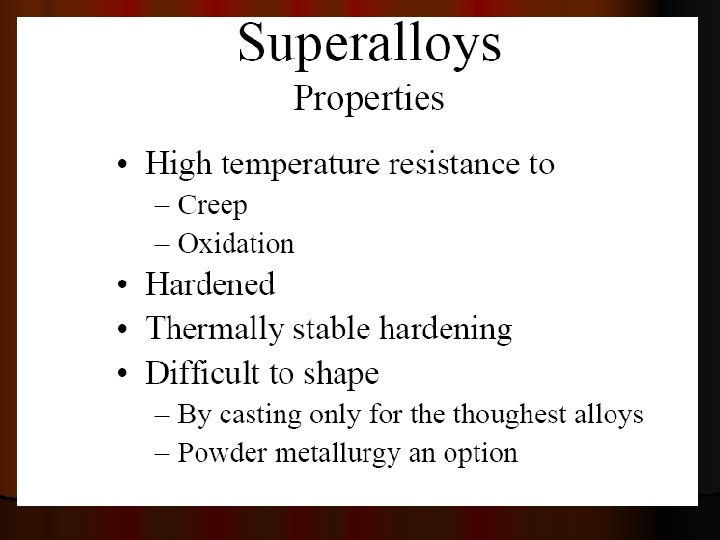
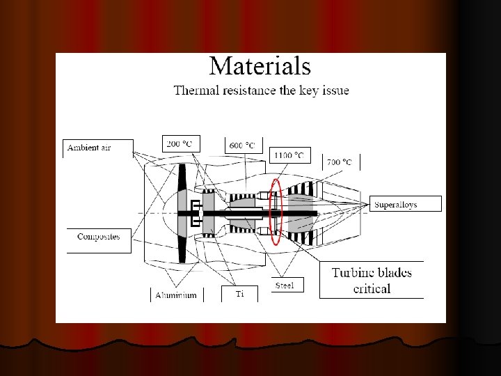
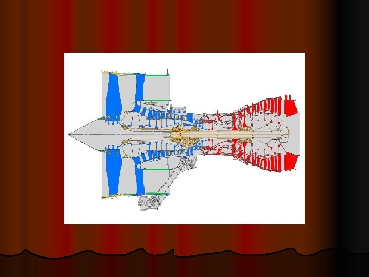
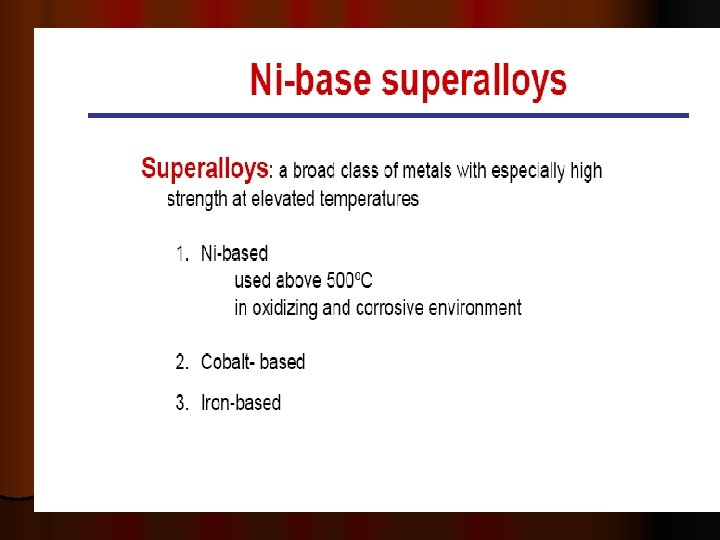
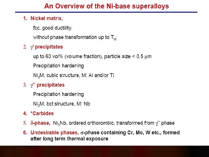
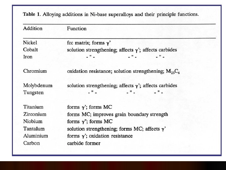
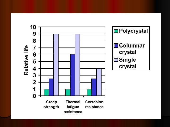
SUPER ALLOYS
l The different materials used in a Rolls-Royce jet engine. In blue, titanium is ideal for its strength and density, but not at high temperatures, where it is replaced by nickelbased superalloys (red). In orange: steel used for the static parts of the compressor.
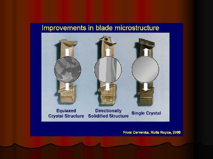
SINGLE CRYSTAL SOLIDIFICATION