Aircraft Icing 1 2 Icing Factors Liquid water


- Slides: 58

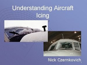
Aircraft Icing 1

2

Icing Factors • • Liquid water content Temperature Droplet size Cloud type Airfoil geometry Airspeed Duration of exposure 3

Where Icing is Likely to Occur 4

Icing Risk Most icing tends to occur at temperatures between 0°and -20°C – More than 50% of those occur between -8 and -12°C - Heaviest icing usually will be found at or slightly above the freezing level 5

Causation of Icing • NOT caused by ICE in clouds. • Caused by “Super-cooled” liquid water droplets – Strike the leading edge of an airfoil – Freeze on impact • For icing to occur – – the aircraft must be flying through visible water such as rain or cloud droplets, and – the temperature at the point where the moisture strikes the aircraft must be 0° C or colder. • Aerodynamic cooling can lower temperature of an airfoil to 0° C even though the ambient temperature is a few degrees warmer 6

Icing Type Classification • Types – Clear – Rime – Mixed • Classified based on the structure and appearance of the ice • Type of ice varies based on the atmospheric and flight conditions in which it forms 7

8

Frequency of Icing Types 9

Clear Ice • Glossy, transparent ice formed by the relatively slow freezing of super cooled water – Often contains some air pockets that result in a lumpy translucent appearance • Clear ice is denser, harder, and sometimes more transparent than rime ice • With larger accumulations, clear ice may form “horns. ” • Forms when – – – Temperatures are close to freezing Large amounts of liquid water are present High aircraft velocity Large droplets are present Clear icing most likely in building Cumulus • Removal of clear ice by deicing equipment is especially difficult 10

Rime Ice • • • Rough, milky, opaque ice Formed by the instantaneous or very rapid freezing of super cooled droplets as they strike the surface – Freezes before the drop has time to spread Rapid freezing results in the formation of air pockets in the ice, giving it an opaque appearance and making it porous and brittle For larger accretions, rime ice may form a streamlined extension of the wing Forms when: – Temperatures are low – Lower amounts of liquid water present – Low velocity – Small droplets are present Irregular shape and rough surface make it very effective in decreasing aerodynamic efficiency, but it is lighter than clear ice 11

Mixed Ice • Mixed ice is a combination of clear and rime ice • Shape and roughness of the ice is the most important aspect from an aerodynamic point of view. 12

Icing Severity Accumulation Rate Description to Report to ATC Condition of Ice Accumulation Pilot Action Trace Ice becomes perceptible. Rate of accumulation slightly greater than rate of sublimation. It is not hazardous even though deicing/anti-icing equipment is not utilized, unless encountered for an extended period of time - over one hour. Unless encountered for one hour or more, deicing/anti-icing equipment and/or heading or altitude change not usually required. Light The rate of accumulation may create a problem if flight is prolonged in this environment (over one hour). Occasional use of deicing/anti-icing equipment removes/prevents accumulation. It does not present a problem if the deicing/anti-icing equipment is used. Deicing/anti-icing required occasionally to prevent accumulation and/or heading or altitude change required. Moderate The rate of accumulation is such that even short encounters become potentially hazardous and use of deicing/anti-icing equipment or diversion is necessary. Deicing/anti-icing required or heading or altitude change required. Severe The rate of accumulation is such that deicing/antiicing equipment fails to reduce or control the hazard. Immediate diversion is necessary. Immediate heading or altitude change required. 13

Icing Severity Accumulation Rate Light Moderate Severe 14

Freezing Rain • Heavy icing in short time • Warm air/moisture over-running Cold air • Begins as rain, – Then falls through cold air – Becomes super cooled water – Freezes on impact • Best maneuver maybe to gain altitude • Check with a weather briefer first! 15

Cloud Type and Icing • Stratus clouds – Typically contain lower amounts of liquid water than cumulus clouds – Thickness can go to several thousands of feet; however, the vertical exent of an icing layer in a stratus cloud usually does not exceed 3, 000 feet – Icing in stratiform clouds is usually found in the higher temperature mid-to low-level clouds below 15, 000 feet AGL – Immediately activate ice protection systems. Monitor closely, and change altitude by at least 3, 000 feet to avoid prolonged icing exposure • Cumulus clouds – Vertical development can cause the range of icing to cover many thousands of feet – Often contain high amounts of liquid water and larger droplet sizes – Icing is most intense in the updrafts that have high liquid water content, which sometimes support Super large droplets – Icing usually found below 27, 000 feet at temperatures between +2° and -20°C. – Icing is usually of short in duration, but can be severe in intensity – Attempt to maintain visual separation from the clouds • Icing risk can increase near large bodies of water, since moisture added to overlying air masses increases water content 16

Known Icing • Generally known icing conditions exist when visible moisture or high relative humidity combines with temperatures near or below freezing • Since clouds are a form of visible moisture, flying through clouds at an altitude that is near or below freezing would constitute flight into known icing conditions • It doesn't matter whethere any reports or forecasts of icing conditions at any altitude anywhere near the route of flight – determination of known icing is based upon temperature and moisture • The threat of ice need not cover an entire area at all altitudes for the threat to be known or dangerous 17

Aircraft Certification • Aircraft are either FAA approved for flight in icing conditions or not – Icing approval involves significant testing – Few light aircraft are approved for flight in icing – Aircraft that do not have all required ice protection equipment installed and functional are prohibited from venturing into an area with known icing conditions – Limited anti/de-icing equipment, such as a heated propeller or windshield, does not prepare an aircraft for flight in icing conditions • Only makes escape from an inadvertent encounter a little easier • Flight into known icing conditions when the airplane flight manual or pilot operating handbook prohibits such flight would constitute a violation whether the aircraft accretes ice or not 18

Types of Icing • Structural Icing – Accumulation of ice on the exterior of the aircraft • Forms on aircraft structures and surfaces when super-cooled droplets land on them and freeze • Small and/or narrow parts rapidly collect droplets and ice up most rapidly – This is why a small protuberance within the pilot’s vision can be used as an “ice evidence probe” It is generally one of the first parts of the airplane on which an appreciable amount of ice forms – Tailplane is a better collector than wings, because the tailplane presents a thinner surface to the airstream – Structural icing can cause significant aircraft control and performance degradation 19

Where Ice Forms 20

Structural Icing • Thin wings are more critical with ice on them than thick wings • Tail Stall – If the tail stalls due to ice and the airflow disruption it causes, recovery is unlikely at low altitudes – Less familiar to many pilots • Wing stall – Much more common threat – Important to distinguish between tail stall and wing stall, since the required actions are roughly opposite 21

Tail Stall • What Is a Tail Stall? – Horizontal stabilizer balances the tendency of the nose to pitch down by generating downward lift on the tail of the aircraft to counter CG being forward of CP – When the tail stalls, this downward force is lessened or removed, and the nose of the airplane can severely pitch down – Because the tail has a smaller leading edge radius and chord length than the wings, it collects two to three times more ice than the wings – Tail ice accumulation is often not seen by the pilot 22

Tail Stall • Tailplane stall often worsens with increased airspeed and may worsen with increased power settings at the same flap setting – Airspeed, at any flap setting, in excess of the airplane manufacturer’s recommendations, with ice on the tailplane may cause a tailplane stall and uncommanded pitch down from which recovery may not be possible – Tailplane stall may occur at speeds less than the maximum flap extended speed (VFE) • High engine power settings may adversely impact response to tailplane stall conditions at high airspeed in some aircraft designs – Follow the manufacturer’s recommendations regarding power 23

Tail Stall Recognition • Tail stall Indications – When flaps are extended to any setting, the pitch control forces become abnormal or erratic – Buffet in the control column (not the airframe) – Elevator control pulsing, oscillations, or vibrations – Abnormal nose-down trim change – Any other unusual or abnormal pitch anomalies (possibly resulting in pilot induced oscillations) – Reduction or loss of elevator effectiveness – Sudden change in elevator force (control would move nose-down if unrestrained) – Sudden uncommanded nose-down pitch • Recovery from a tail stall is exactly opposite that for a wing stall recovery – In a tail stall recovery air flow must be restored to the tail's lower airfoil surface, and in a wing stall recovery air flow must be restored to the wing's upper airfoil surface 24

Tail Stall Recovery • Immediately raise flaps to the previous setting • Apply appropriate nose-up elevator pressure • Reduce power if altitude permits; otherwise maintain power – May need power increase if flaps are retracted, however – Do not increase airspeed unless it is necessary to avoid a wing stall • Make nose-down pitch changes slowly, even in gusting conditions, if circumstances allow 25

Wing Icing • Ice can distort the flow of air over the wing – – – Diminishes the wing's maximum lift Reduces the angle of attack for maximum lift Adversely affects airplane handling qualities Significantly increases drag Will ordinarily stall at a lower angle of attack, and thus a higher airspeed • Small amounts of ice will have an effect, and if the ice is rough, it can be a large effect – Frost, snow, and ice accumulations (on the leading edge or upper surface of the wing) no thicker or rougher than a piece of coarse sandpaper can reduce lift by 30 percent and increase drag up to 40 percent – Larger accretions can reduce lift even more and can increase drag by 80 percent or more 26

Wing Icing • Increased approach speed is advisable if ice is on the wings – How much of an increase depends on both the aircraft type and amount of ice – Refer to the POH • Stall characteristics of an aircraft with ice-covered wings will be degraded • Ice accretion may be asymmetric between the two wings • Outer part of a wing, which is ordinarily thinner and thus a better collector of ice, may stall first rather than last 27

Detecting Wing and Airframe Icing • Most obvious early symptom of airframe / wing icing in flight will be a decrease in airspeed – May also see ice on small narrow areas around the windshield and on struts • Visual inspection on the ground and inflight – Use of a flashlight can be very helpful – Ice is often difficult to see and in many instances cannot be detected other than by touch with the bare hand so should conduct visual and tactile inspections – inspections of airplane wing upper surfaces – May make the aircraft’s critical surfaces appear to be wet or the same color as the wing – During night operations, adequate illumination should be used to observe ice on the ground and in flight • Some aircraft have electronic ice detectors 28

Icing Impact on Roll Control • Ice on the wings forward of the ailerons can affect roll control – Serious roll control problems are not unusual – Possible for uncommanded and uncontrolled rolls to occur • Roll upset may be caused by airflow separation (aerodynamic stall), which induces selfdeflection of the ailerons and loss of or degraded roll handling characteristics • Wings on GA aircraft are designed so that stall starts near the root of the wing and progresses outward, so the stall does not interfere with roll control of the ailerons • Since wing tips are thinner and most efficiently collect ice - can lead to a partial stall of the wings at the tips, which can affect the ailerons and thus roll control • If ice accumulates in a ridge aft of the boots but forward of the ailerons, this can affect the airflow and interfere with proper functioning of the ailerons • If aileron function is impaired due to ice, slight forward pressure on the elevator may help to reattach airflow to the aileron 29

Pitot Tube / Static Port Icing • A completely blocked pitot tube (e. g. , due to an inoperative heater) will cause the airspeed indicator to function like an altimeter – As the aircraft climbs, so does the airspeed. As the aircraft descends, so does the airspeed indication • Various instruments (e. g. , airspeed indicator, altimeter, and VSI) utilize pressures sensed by the pitot tube and static port – When iced these instruments display incorrect information 30

Propeller Icing • Ice buildup on propeller blades reduces thrust • The greatest quantity of ice normally collects on the spinner and inner radius of the propeller • Propeller areas on which ice may accumulate and be ingested into the engine normally are anti-iced rather than deiced to reduce the probability of ice being shed into the engine 31

Stall Warning Systems • Icing may result in the possible loss of stall warning system effectiveness – Exacerbates an already hazardous situation • Even if the stall warning system is operational, it may be ineffective because the wing stalls at a lower angle of attack due to ice on the wing 32

Other Icing Impacts • In certain icing conditions, control surfaces may bind or jam as a result of icing – Some approved aircraft have space around the edges of control surfaces to allow ice to build up without interfering with their movement • Unheated fuel vents can become blocked, which may lead to fuel starvation – Fuel tanks, especially bladder types, may collapse because air is unavailable to replace the used fuel • Limited vision – Icing may block windscreen blocking enough forward vision to see ahead enough to land 33

Communications • Because of their small size and shape, antennas that do not lay flush with the aircraft’s skin tend to accumulate ice rapidly • Ice accumulations may cause: – Antenna to vibrate – Radio signals to become distorted – Damage to the antenna • If a frozen antenna breaks off, it can damage other areas of the aircraft in addition to causing a communication or navigation system failure 34

Ice Weight Impact • Weight of ice may prevent an aircraft from: – Taking off – Maintaining altitude – Significantly alter CG • How much ice can a non-approved aircraft can carry? – It is unknown – It was never determined through testing 35

Fuel System Icing • • • Ice formation in fuel systems results from dissolved and undissolved water in the fuel Dissolved water in solution with fuels constitutes a relatively small part of the total water potential in a fuel system. Water strictly in solution is not a serious problem in aviation fuel so long as it remains in solution. Undissolved water is entrained water, such as water particles, suspended in the fuel as a result: – Mechanical agitation of free water – Conversion of dissolved water through temperature reduction – May be introduced as a result of refueling or the settling of entrained water which collects at the bottom of a fuel – May also be introduced as a result of condensation from air entering a fuel tank through the vent system – Entrained and free water are the most dangerous because of the potential of freezing on the surfaces of the fuel system • Free water can be drained from a fuel tank if low point drain provisions are adequate. Removal of such water can reduce or eliminate the potential for icing problems 36

Fuel System Icing • During flight, the temperature of the fuel in the tanks decreases, due to the decreasing temperatures at altitude – – • Temperature decrease causes precipitation of the dissolved water from the fuel Separated water then drops to the bottom of the tank, because it is denser than the fuel. Since the water is no longer in solution, it can freeze, blocking fuel inlet pipes The entrained water will freeze in cold fuel and tend to stay in solution longer since the specific gravity of ice is approximately the same as that of aircraft fuel Ice crystals begin to form in entrained water in the fuel as the temperature nears the freeze point of water – Due to impurities in the water, this normally takes place at slightly lower temperatures (27 to 31 °F) (-3 to -1 °C) • • As the temperature decreases further, the ice crystals begin to adhere to their surroundings in the form of ice. This is known as the critical icing temperature and occurs at about 12 to 15 °F (-11 to -9 °C) At temperatures below 0 °F (-18 °C), ice crystals tend to become larger and can plug small openings such as screens, filters, and orifices 37

Fuel System Icing • Anti icing agents – Fuel System Icing Inhibitors (FSII) help to prevent the formation of ice crystals – Typically an Ethylene Glycol mixture – FSII dissolves in more easily in water then fuel. Any water present will extract FSII from the fuel; the additive then acts to reduce the freeze point of the free water, preventing the formation of ice crystals – FSII must be distributed evenly throughout the fuel – can’t just pour in the tank – FSII depresses the freezing point of the water to -43°C. – Some FSII formulations are highly toxic and must be stored properly in dry conditions – Normally prepared for jet fuel, but some brands are good with 100 LL – Check the label • Fuel Heaters – Operate using the principle of heat exchange to warm the fuel • Can use engine bleed air, an air-to-liquid exchanger, or engine lubricating oil, a liquid-to-liquid exchanger, as a source of heat. – Protects the engine fuel system from ice formation and can also be used to thaw ice – In some cases the fuel filter is fitted with a pressure-drop warning switch which illuminates a warning light if ice collects on the filter surface – Fuel deicing systems are designed to be used intermittently • Controlled manually by a switch in the cockpit or automatically using a thermostat 38

Deicing and Anti-Icing Equipment • Anti-icing equipment is turned on and used before entering icing conditions – Includes carburetor heat, prop heat, pitot heat, fuel vent heat, windshield heat, and fluid surface deicers (in some cases). • • Deicing is used after ice has built up to an appreciable amount. Typically this includes surface deice equipment – e. g. boots Propeller – Ice often forms on the propeller before it is visible on the wing – Deicing fluid can be applied by slinger rings on the prop hub – Propeller can be de-iced by electrically heated elements on the leading edges • Wing – Boots are de-icing devices – most common system • Boots are inflatable rubber strips attached to the leading edge of the wing and tail surfaces. When inflated they expand, breaking ice off the boot surfaces. Following inflation, suction is applied to the boots and they return to their original shape – Two types of anti-icing systems • Weeping wing systems (fluid deice systems) - pump fluid from a reservoir through a mesh screen embedded in the wing’s leading edge • Heated wing - typically found on jets 39

Deicing and Anti-Icing Equipment • Windshield - two systems used in light aircraft – Electrically heated windshield, or plate – Fluid de-icing spray onto the windshield – Icing can also be controlled to a very limited extent with the windshield defroster • Never acceptable by itself • On many aircraft it is the only source of windshield ice prevention 40

Deicing and Anti-Icing Equipment • Unprotected areas of an aircraft with anti / deicing equipment can still have a significant performance impact, even after use of the equipment – Close to 30 percent of the total drag associated with an ice encounter remained after all the protected surfaces were cleared – Non-protected surfaces may include antennas, flap hinges, control horns, fuselage frontal area, windshield wipers, wing struts, fixed landing gear, etc. 41

What about Using Anti-Icing Fluid • Consult your Pilot Operating Handbook (POH) for specific information • General guidance – Key factor is rotation speed – Rotation speed of <60 knots, normally only consider Type I fluid • Type I fluid is orange in color and mostly glycol • Protection time is limited - five minutes or less – Rotation speed is 60 knots or more, may be able to use Type III fluid, if approved by the airframe manufacturer – Only if rotation speed is 110 knots or more, should you consider using Type II or IV fluid—and then only if approved by the airframe manufacturer 42

Induction Icing • • • Ice in the induction system reduces the amount of air available for combustion Induction icing accidents is the number one cause of icing accidents – 52% Carburetor ice – Occurs when moist air passes through a carburetor venturi and is cooled • Carburetion process can lower the temperature of the incoming air as much as 60 degrees F – Ice may, as a result, form on the venturi walls and throttle plate, restricting airflow to the engine – Generally occurs at temperatures between 20° F (-7° C) and 70° F (21° C) • Can form even when the skies are clear and the outside air temperature is as high as 90 degrees – Indicated by reduced rpm with a fixed-pitch propeller and a loss of manifold pressure with a constant speed propeller, and may make the engine run rough – Remedied by applying carburetor heat, which uses exhaust as a heat source to melt the ice or prevent its formation 43

Induction Icing – At the first indication of carburetor ice • Apply full carburetor heat and leave it on • Engine may run rougher as the ice melts and goes through it, but it will smooth out • When the engine runs smoothly, turn off the carb heat – If you shut off the carburetor heat prematurely, the engine will build more ice— and probably quit because of air starvation. • The engine rpm should return to its original power setting. If the rpm drops again, fly with the carb heat on • Do not use partial heat – it will make the icing worse • With carburetor heat on, the hot air is less dense, so the mixture becomes richer, and as a result, the rpm will drop a bit further. Lean the mixture, and most of the rpm loss should return. 44

Induction Icing • Fuel-injected aircraft induction icing – Engines are less vulnerable to icing – Can be affected if the engine’s air source (air filter and intake passages) becomes blocked with ice – Manufacturers provide an alternate air source to remedy the situation – At the first indication of induction icing • Activate the alternate induction air door or doors – When these doors open, intake air routes through them, bypassing the ice blocked normal induction air pathway – Some alternate induction air systems activate automatically using springloaded doors • Check the POH to ascertain how and when to use this system 45

Induction Icing • Jet aircraft – Air that is drawn into the engines creates an area of reduced pressure at the inlet, which lowers the temperature below that of the surrounding air. This reduction in temperature may be sufficient to cause ice to form on the engine inlet, disrupting the airflow into the engine – Hazard may also occur when ice breaks off and is ingested into a running engine, which can cause damage to fan blades, engine compressor stall, or combustor flameout – When anti-icing systems are used, runback water also can refreeze on unprotected surfaces of the inlet and, if excessive, reduce airflow into the engine or distort the airflow pattern in such a manner as to cause compressor or fan blades to vibrate, possibly damaging the engine – Icing of engine probes used to set power levels (for example, engine inlet temperature or engine pressure ratio (EPR) probes), can lead to erroneous readings of engine performance, reduced power or total power loss. • The type of ice that forms can be classified as clear, rime, or mixed, based on the structure and appearance of the ice. The type of ice that forms varies depending on the atmospheric and flight conditions in which it forms. Significant structural icing on an aircraft can cause serious aircraft control and performance problems. 46

Ice Avoidance flight plan • Fairly easy to predict where large areas of icing potential exist • Accurate prediction of specific icing areas and altitudes is much harder • All clouds are not alike. There are dry clouds and wet clouds • Fronts and low-pressure areas are the biggest ice producers, but isolated air mass instability with plenty of moisture can produce significant icing • Freezing rain and drizzle are very dangerous 47

Ice Avoidance flight plan • For VFR flights, with the exceptions of freezing rain, freezing drizzle, and carburetor icing, staying clear of clouds by a safe margin generally will prevent ice formation • For IFR Flights – Get a good briefing – use all resources • • • Know the big picture because most ice is in fronts and low-pressure centers Cloud tops and bases Temperatures Look at alternate routes Have an escape route - could be a climb, descent, 180 -degree turn, or immediate landing at a nearby airport – Request Pireps pre-flight and enroute • Type of aircraft making the pirep is important • Single reports not always accurate – Provide Pireps for others 48

Ice Pre-Flight Actions • Carry extra fuel. In icing conditions, extra power is needed because of increased aerodynamic drag and/or because carburetor heat is used. Fuel consumption will increase • Remove all frost, snow, or ice from the wings - Don't count on blowing snow off when taking off. There could be some nasty sticky stuff underneath the snow • Check for ice and snow elsewhere – Propeller dry and clean – Check controls to be sure there is full freedom of movement in all directions – Check the landing gear and clean off all accumulated slush • Wheelpants on fixed-gear aircraft should be removed in winter operations because they are slush collectors • Check wheel wells for ice accumulation • Be sure that deice and anti-ice equipment works. When was the last time you actually checked the pitot heat for proper functioning 49

Weather Products • Current Icing Potential (CIP) – Shows expected potential for icing, but does not yet show severity – Gives icing potential information for particular altitudes and geographic locations, but should be used as a supplement to an official weather briefing • Forecast Icing Potential (FIP) 50

Weather Products • Icing sigmets – Issued for severe icing (not associated with thunderstorms -- otherwise, it is a convective sigmet) • AIRMET Zulu – Describes moderate icing and provides freezing-level heights • Freezing level graphics 51

Departures in Icing Conditions • Taxi slowly on icy taxiways • Be careful on run-up – aircraft may slide • Know where the cloud bases and the tops are – If you encounter icing conditions, have a plan either to return to the airport or climb above the ice • Consider cycling the gear after takeoff to help shed ice from the landing gear • Do not climb too steeply as it may cause ice to form on the underside of the wing behind the boots – Ice on the underside of the wing increases drag, sometimes dramatically 52

Enroute • Airspeed is a key to measuring ice accumulation. – If normal cruise drops, it's time to exit immediately – If you can't climb or descend, then a 180 -degree turn is the only option, and that will result in a loss of at least another 10 KIAS until you're out of the ice – A 20 -knot drop in airspeed is plenty. Add power to increase airspeed, since stall speed margins shrink with speed loss – Speed discipline is key in icing conditions – Aircraft not certified for flight into icing conditions should start getting out of icing conditions at the first sign of ice. • At the first sign of ice accumulation, decide what action you need to take and advise ATC – Do you know where warmer air or a cloud-free altitude is – If you need to modify your route to avoid ice, be firm with ATC about the need to change altitude or direction as soon as possible • Requesting an immediate climb, descent, or turn lets the controller know that unless the request is handled quickly an emergency situation will likely develop – Don't wait until the situation deteriorates – Declare an emergency if necessary to solve the problem 53

Enroute • If you're on top of a cloud layer and can stay on top, ask ATC for a climb well before getting into the clouds – Icing is much worse in the tops of the clouds • If you're in the clouds and the temperature is close to freezing, ask for a top report ahead – Can tell you whether going up is a better option than descending • Around mountains be extra cautious – The air being lifted up the mountain slopes by the wind (orographic lifting) produces moderate to severe icing 54

Autopilot • Do not use the autopilot in icing conditions – Masks the aerodynamic effects of the ice and may bring the aircraft into a stall or cause control problems – Situation can degrade to the point that autopilot servo control power is exceeded, disconnecting the autopilot • Pilot is then faced with an immediate control deflection for which there was no warning or preparation 55

Approach and Landing With Ice • • • Most icing accidents occur in the approach and landing phases of flight If on top of ice-laden clouds, request ATC's permission to stay on top as long as possible When carrying ice do not lower the flaps – The airflow change resulting from lowering the flaps may cause a tail with ice to stall • Carry extra power and speed on final approach — at least 10 to 20 knots – Stall speed is increased when carrying Ice • Many icing accidents occur when the aircraft is maneuvering to land – Shallow bank turns should be used as the stall potential is high • Use the longest runway possible – Because of increased airspeed and the no-flap configuration – May also be ice on the runway • Turn the defroster on high to possibly help keep a portion of the windshield clear – Turn off the cabin heat if that will provide more heat to the windshield. • If the windshield is badly iced, open the side window and attempt to scrape away a small hole using an automotive windshield ice scraper, credit card, or other suitable object – Be careful not to lose control of the aircraft when removing ice from the windshield 56

Also Look at the FAA’s Pilot’s Guide to Flight in Icing Conditions for more detail – http: //rgl. faa. gov/Regulatory_and_Guidan ce_Library/rg. Advisory. Circular. nsf/list/AC% 2091 -74/$FILE/AC 91 -74. pdf 57

Disclaimer • Instrument flight can be dangerous. Do not rely solely on this presentation – PROFESSIONAL INSTRUCTION IS REQUIRED • The foregoing material should not be relied upon for flight • ALTHOUGH THE ABOVE INFORMATION IS FROM SOURCES BELIEVED TO BE RELIABLE SUCH INFORMATION HAS NOT BEEN VERIFIED, AND NO EXPRESS REPRESENTATION IS MADE NOR IS ANY TO BE IMPLIED AS TO THE ACCURACY THEREOF, AND IT IS SUBMITTED SUBJECT TO ERRORS, OMISSIONS, CHANGE 58
 Rime icing
 Water and water and water water
 Example of pure liquid dielectric is
 Triangular diagram for liquid-liquid extraction
 Ice crystal icing
 Flat type icing
 Ganache define
 Royal icing ce
 Icing sugar wiki
 Face off spelhervatting
 Carburetor icing
 Tat sat temperature
 Compressed liquid water
 Mass and volume definition
 Adiabatic liquid water content
 Why is water colourless
 Site vs. situation
 Is a wooden chair biotic or abiotic
 Abiotic factors and biotic factors
 Aboitic environment
 Is tulip biotic or abiotic
 Site factors vs situation factors
 Factors of 18
 Common factors of 10 and 20
 Gcf of 56
 Keel surface of aircraft
 Aircraft configuration management
 Wdm manual aircraft
 Aircraft maintenance planning and control
 Engine ogv
 Aircraft onboard inert gas generation system
 Log book entries example
 The tilting or turning of a gyro in response to pressure
 Double acting unbalanced actuator
 Glideslope indicator
 Robert fugard
 Grumman aircraft engineering corporation
 Search and rescue aircraft signals
 Aircraft static margin
 Aircraft static margin
 Cpa aviation
 Aircraft static margin
 Apron safety lines colour
 Aircraft electrical components
 Bank owned aircraft
 Continuous airworthiness maintenance program (camp)
 Aircraft builders council
 Bada aircraft performance summary tables
 Aircraft meteorological data relay
 Aircraft maintenance organization chart
 Aircraft maintenance forms
 Aircraft maintenance cost breakdown
 Aircraft phase inspection
 Aircraft hydraulic systems
 Faa aircraft design group classification
 Airport characteristics related to airport design
 Aging aircraft solutions
 Stall speed increase with bank angle
 Weedhopper ultralight
