
Agilent Technologies Free Space Materials Characterization Shelley Blasdel
Agilent Technologies Free Space Materials Characterization Shelley Blasdel Begley Application Development Engineer Page 1 Agilent Technical Forum Free Space Materials Characterization 15 October 2008
Agilent Technologies Agenda What is it? Free Space Measurement Systems Calibration Measurement Results Page 2 Agilent Technical Forum Free Space Materials Characterization 15 October 2008
What is Free Space Materials Characterization? Measuring Electromagnetic Properties of Materials Using Free Space Measurement Technique. Important for: Circuit design Military Applications Car Radar Applications New Materials Research Incoming Inspection Quality Assurance Health and Safety and more… Page 3 Agilent Technical Forum Free Space Materials Characterization 15 October 2008
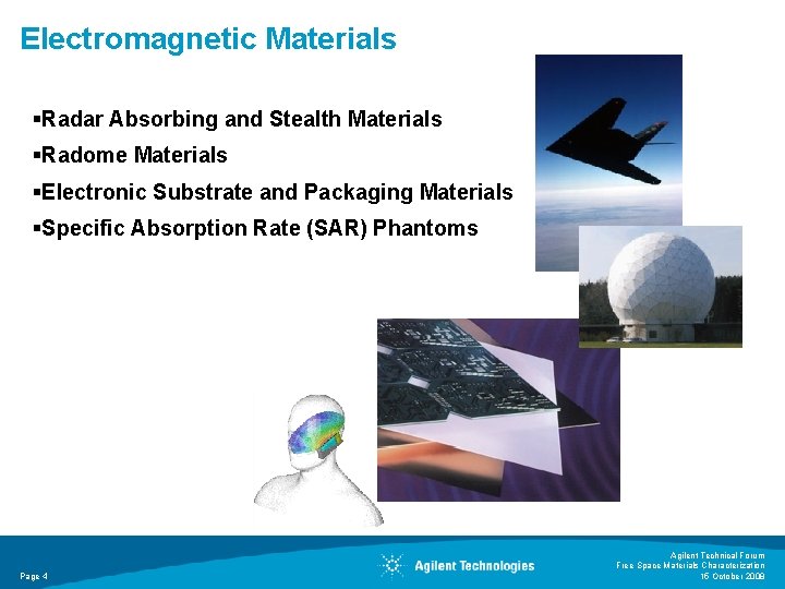
Electromagnetic Materials §Radar Absorbing and Stealth Materials §Radome Materials §Electronic Substrate and Packaging Materials §Specific Absorption Rate (SAR) Phantoms Page 4 Agilent Technical Forum Free Space Materials Characterization 15 October 2008
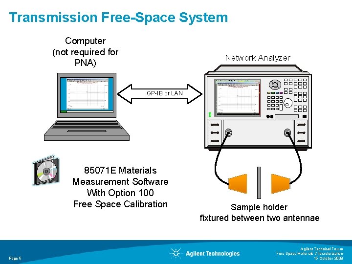
Transmission Free-Space System Computer (not required for PNA) Network Analyzer GP-IB or LAN 85071 E Materials Measurement Software With Option 100 Free Space Calibration Page 5 Sample holder fixtured between two antennae Agilent Technical Forum Free Space Materials Characterization 15 October 2008
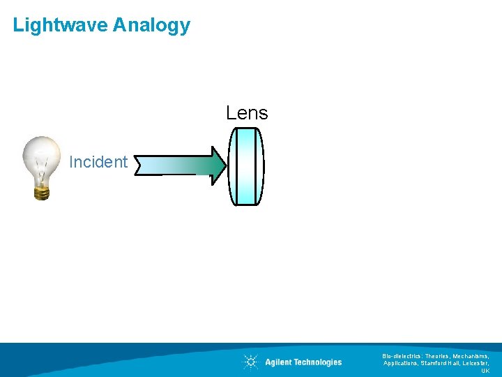
Lightwave Analogy Lens Incident Bio-dielectrics: Theories, Mechanisms, Applications, Stamford Hall, Leicester, UK
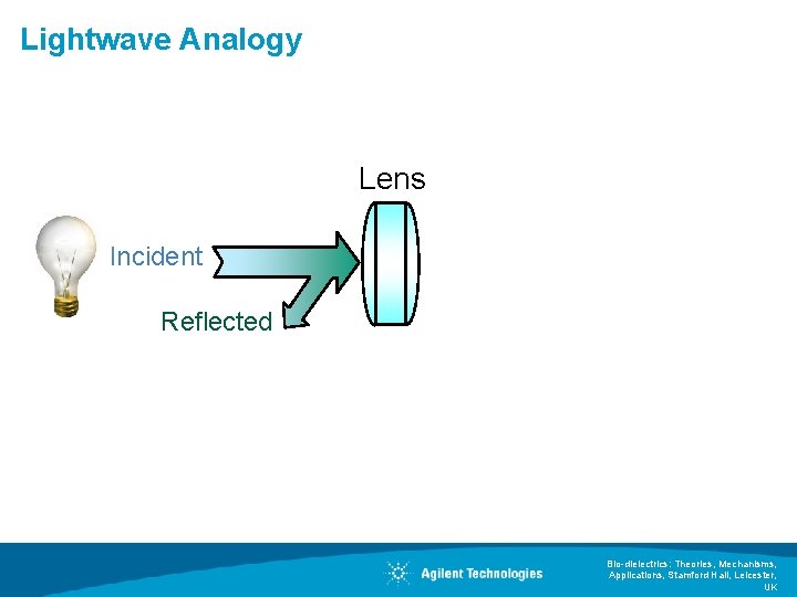
Lightwave Analogy Lens Incident Reflected Bio-dielectrics: Theories, Mechanisms, Applications, Stamford Hall, Leicester, UK
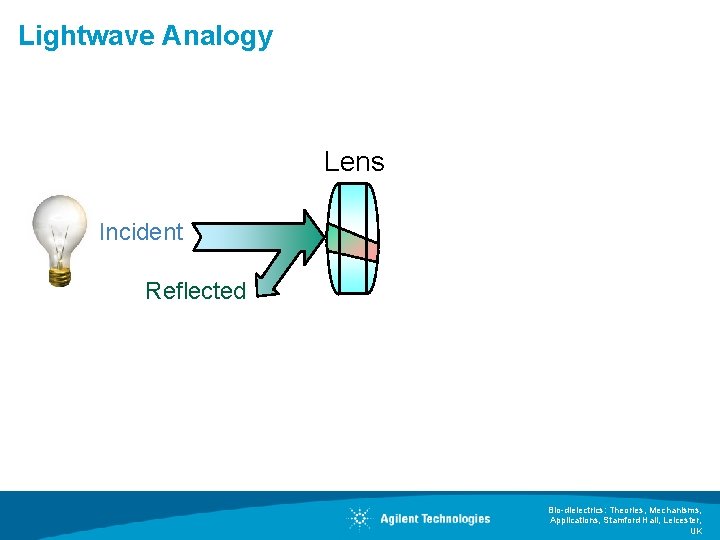
Lightwave Analogy Lens Incident Reflected Bio-dielectrics: Theories, Mechanisms, Applications, Stamford Hall, Leicester, UK
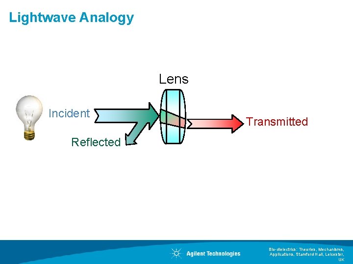
Lightwave Analogy Lens Incident Transmitted Reflected Bio-dielectrics: Theories, Mechanisms, Applications, Stamford Hall, Leicester, UK
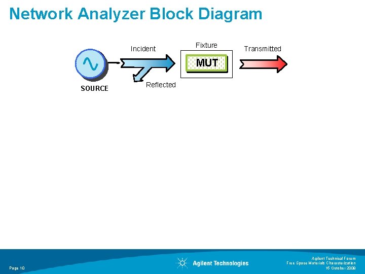
Network Analyzer Block Diagram Incident Fixture Transmitted MUT SOURCE Page 10 Reflected Agilent Technical Forum Free Space Materials Characterization 15 October 2008
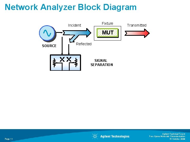
Network Analyzer Block Diagram Fixture Incident Transmitted MUT SOURCE Reflected SIGNAL SEPARATION Page 11 Agilent Technical Forum Free Space Materials Characterization 15 October 2008
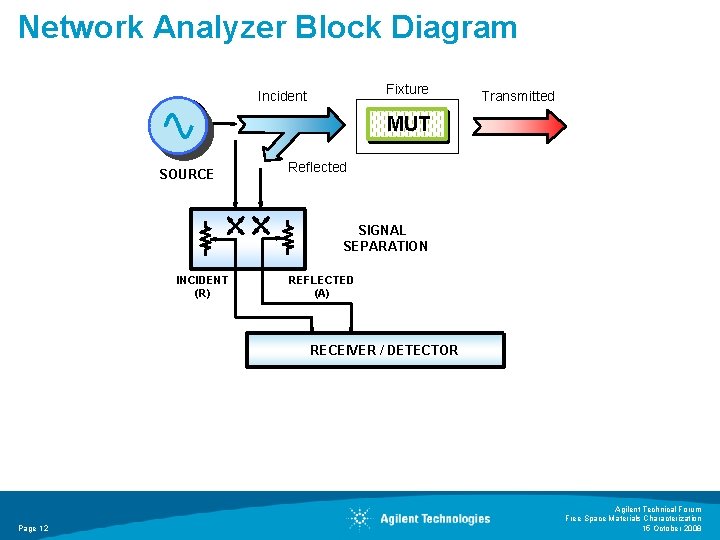
Network Analyzer Block Diagram Fixture Incident Transmitted MUT SOURCE Reflected SIGNAL SEPARATION INCIDENT (R) REFLECTED (A) RECEIVER / DETECTOR Page 12 Agilent Technical Forum Free Space Materials Characterization 15 October 2008
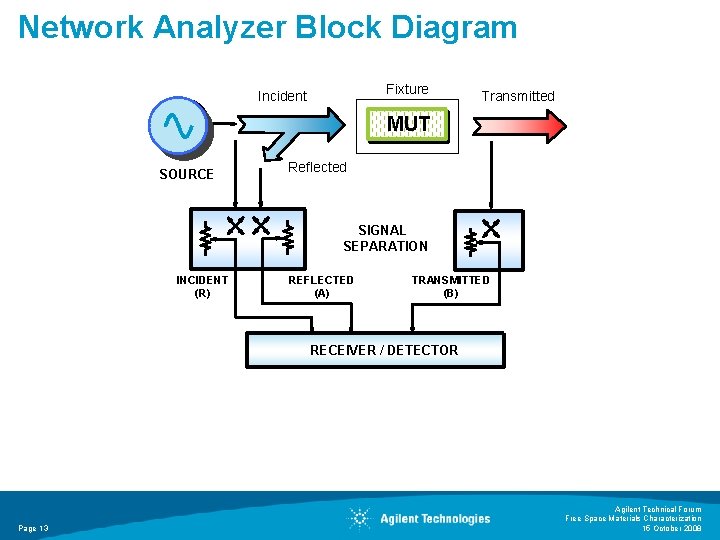
Network Analyzer Block Diagram Fixture Incident Transmitted MUT SOURCE Reflected SIGNAL SEPARATION INCIDENT (R) REFLECTED (A) TRANSMITTED (B) RECEIVER / DETECTOR Page 13 Agilent Technical Forum Free Space Materials Characterization 15 October 2008
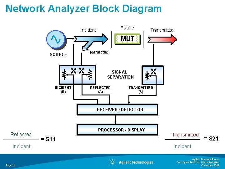
Network Analyzer Block Diagram Fixture Incident Transmitted MUT SOURCE Reflected SIGNAL SEPARATION INCIDENT (R) REFLECTED (A) TRANSMITTED (B) RECEIVER / DETECTOR Reflected Incident Page 14 PROCESSOR / DISPLAY = S 11 Transmitted = S 21 Incident Agilent Technical Forum Free Space Materials Characterization 15 October 2008
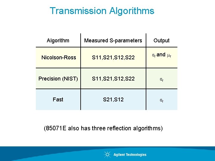
Transmission Algorithms Algorithm Measured S-parameters Output Nicolson-Ross S 11, S 21, S 12, S 22 r and r Precision (NIST) S 11, S 21, S 12, S 22 r Fast S 21, S 12 r (85071 E also has three reflection algorithms)
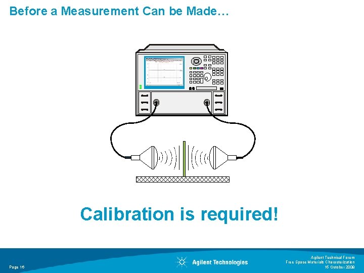
Before a Measurement Can be Made… Calibration is required! Page 16 Agilent Technical Forum Free Space Materials Characterization 15 October 2008
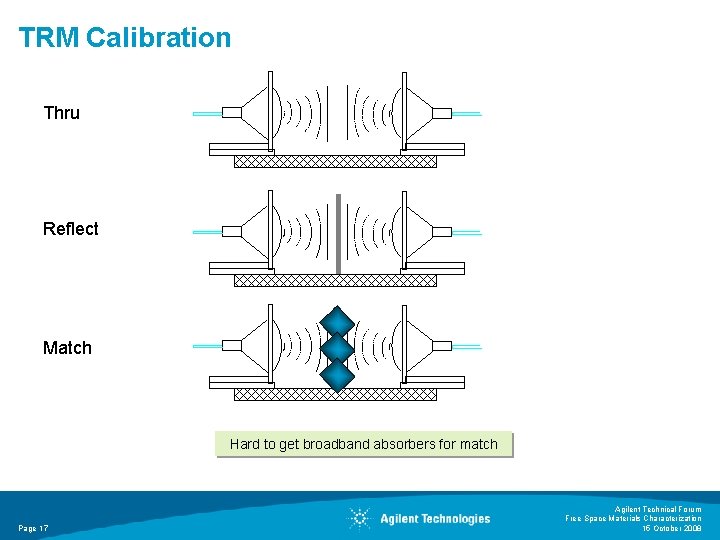
TRM Calibration Thru Reflect Match Hard to get broadband absorbers for match Page 17 Agilent Technical Forum Free Space Materials Characterization 15 October 2008
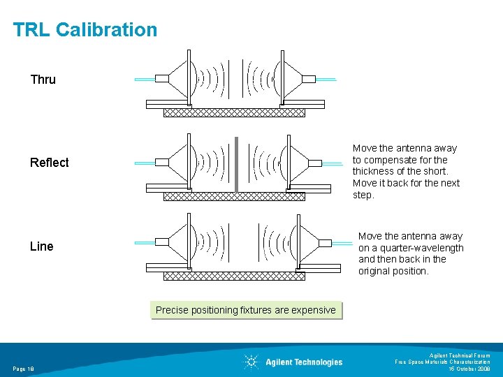
TRL Calibration Thru Move the antenna away to compensate for the thickness of the short. Move it back for the next step. Reflect Move the antenna away on a quarter-wavelength and then back in the original position. Line Precise positioning fixtures are expensive Page 18 Agilent Technical Forum Free Space Materials Characterization 15 October 2008
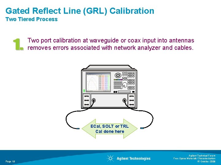
Gated Reflect Line (GRL) Calibration Two Tiered Process Two port calibration at waveguide or coax input into antennas removes errors associated with network analyzer and cables. ECal, SOLT or TRL Cal done here Page 19 Agilent Technical Forum Free Space Materials Characterization 15 October 2008
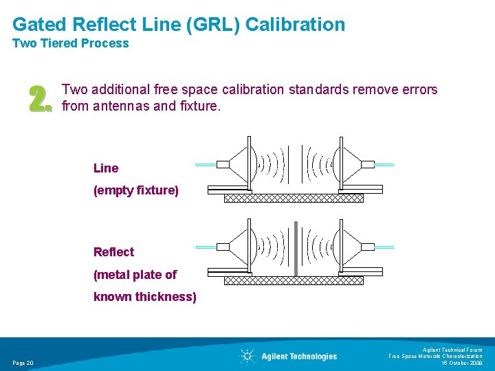
Gated Reflect Line (GRL) Calibration Two Tiered Process Two additional free space calibration standards remove errors from antennas and fixture. Line (empty fixture) Reflect (metal plate of known thickness) Page 20 Agilent Technical Forum Free Space Materials Characterization 15 October 2008
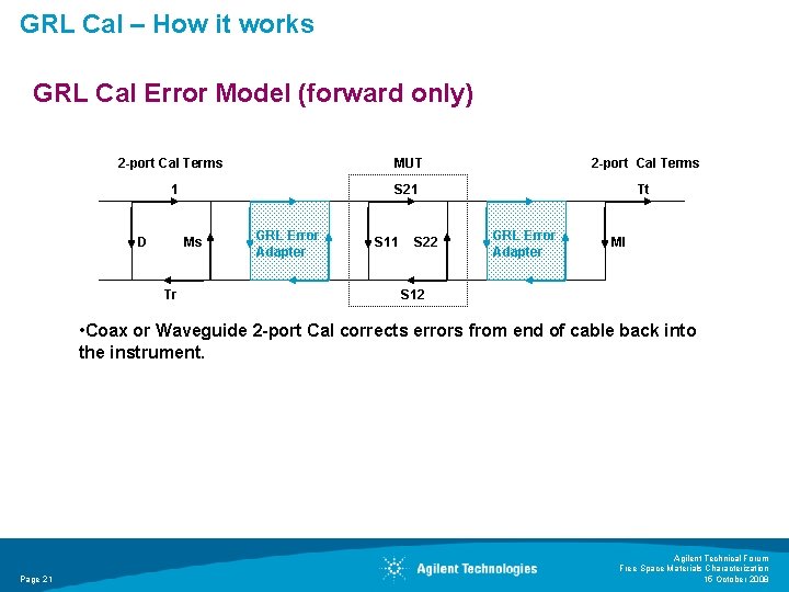
GRL Cal – How it works GRL Cal Error Model (forward only) 2 -port Cal Terms 1 D Ms Tr GRL Error Adapter MUT 2 -port Cal Terms S 21 Tt S 11 S 22 GRL Error Adapter Ml S 12 • Coax or Waveguide 2 -port Cal corrects errors from end of cable back into the instrument. Page 21 Agilent Technical Forum Free Space Materials Characterization 15 October 2008
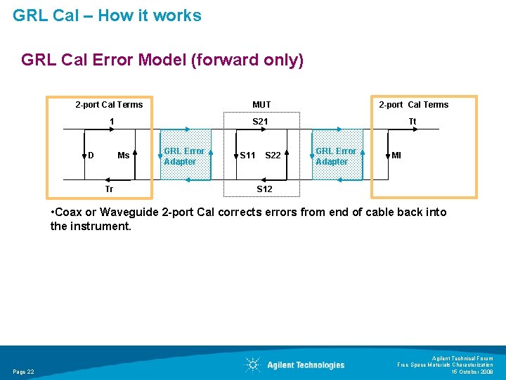
GRL Cal – How it works GRL Cal Error Model (forward only) 2 -port Cal Terms 1 D Ms Tr GRL Error Adapter MUT 2 -port Cal Terms S 21 Tt S 11 S 22 GRL Error Adapter Ml S 12 • Coax or Waveguide 2 -port Cal corrects errors from end of cable back into the instrument. Page 22 Agilent Technical Forum Free Space Materials Characterization 15 October 2008
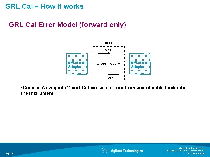
GRL Cal – How it works GRL Cal Error Model (forward only) 2 -port Cal Terms 1 D Ms Tr GRL Error Adapter MUT 2 -port Cal Terms S 21 Tt S 11 S 22 GRL Error Adapter Ml S 12 • Coax or Waveguide 2 -port Cal corrects errors from end of cable back into the instrument. Page 23 Agilent Technical Forum Free Space Materials Characterization 15 October 2008
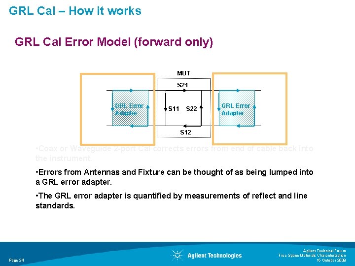
GRL Cal – How it works GRL Cal Error Model (forward only) 2 -port Cal Terms 1 D Ms Tr GRL Error Adapter MUT 2 -port Cal Terms S 21 Tt S 11 S 22 GRL Error Adapter Ml S 12 • Coax or Waveguide 2 -port Cal corrects errors from end of cable back into the instrument. • Errors from Antennas and Fixture can be thought of as being lumped into a GRL error adapter. • The GRL error adapter is quantified by measurements of reflect and line standards. Page 24 Agilent Technical Forum Free Space Materials Characterization 15 October 2008
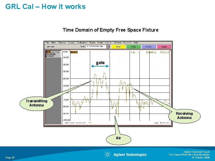
GRL Cal – How it works Time Domain of Empty Free Space Fixture gate Transmitting Antenna Receiving Antenna Air Page 25 Agilent Technical Forum Free Space Materials Characterization 15 October 2008
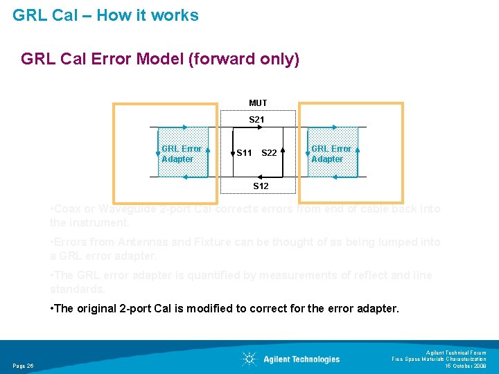
GRL Cal – How it works GRL Cal Error Model (forward only) 2 -port Cal Terms 1 D Ms Tr GRL Error Adapter MUT 2 -port Cal Terms S 21 Tt S 11 S 22 GRL Error Adapter Ml S 12 • Coax or Waveguide 2 -port Cal corrects errors from end of cable back into the instrument. • Errors from Antennas and Fixture can be thought of as being lumped into a GRL error adapter. • The GRL error adapter is quantified by measurements of reflect and line standards. • The original 2 -port Cal is modified to correct for the error adapter. Page 26 Agilent Technical Forum Free Space Materials Characterization 15 October 2008
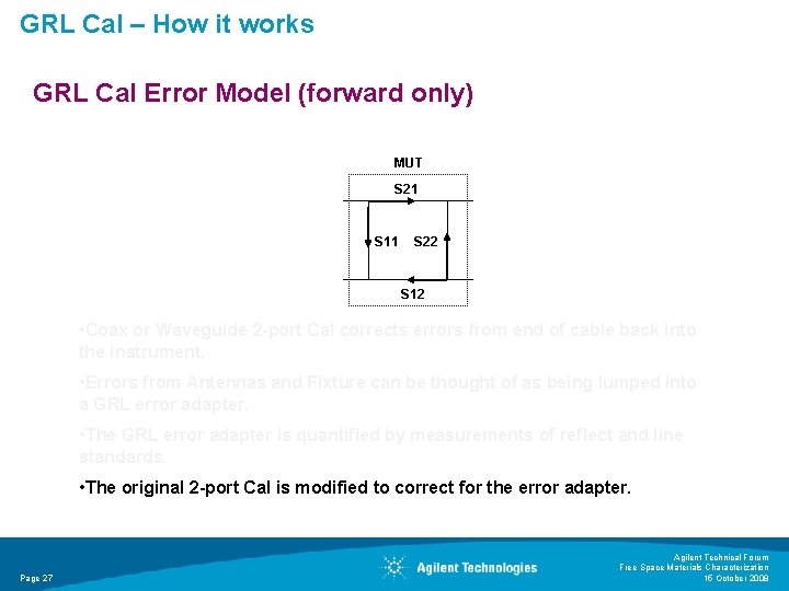
GRL Cal – How it works GRL Cal Error Model (forward only) 2 -port Cal Terms 1 D Ms Tr GRL Error Adapter MUT 2 -port Cal Terms S 21 Tt S 11 S 22 GRL Error Adapter Ml S 12 • Coax or Waveguide 2 -port Cal corrects errors from end of cable back into the instrument. • Errors from Antennas and Fixture can be thought of as being lumped into a GRL error adapter. • The GRL error adapter is quantified by measurements of reflect and line standards. • The original 2 -port Cal is modified to correct for the error adapter. Page 27 Agilent Technical Forum Free Space Materials Characterization 15 October 2008
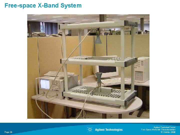
Free-space X-Band System Page 28 Agilent Technical Forum Free Space Materials Characterization 15 October 2008
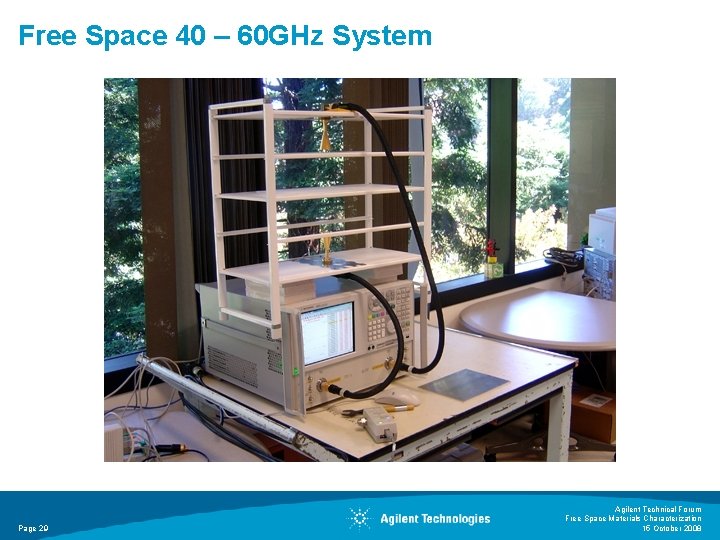
Free Space 40 – 60 GHz System Page 29 Agilent Technical Forum Free Space Materials Characterization 15 October 2008
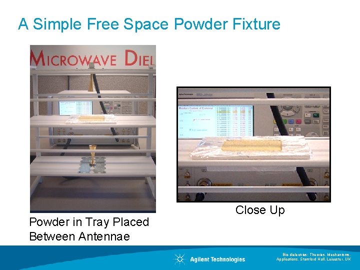
A Simple Free Space Powder Fixture Powder in Tray Placed Between Antennae Close Up Bio-dielectrics: Theories, Mechanisms, Applications, Stamford Hall, Leicester, UK
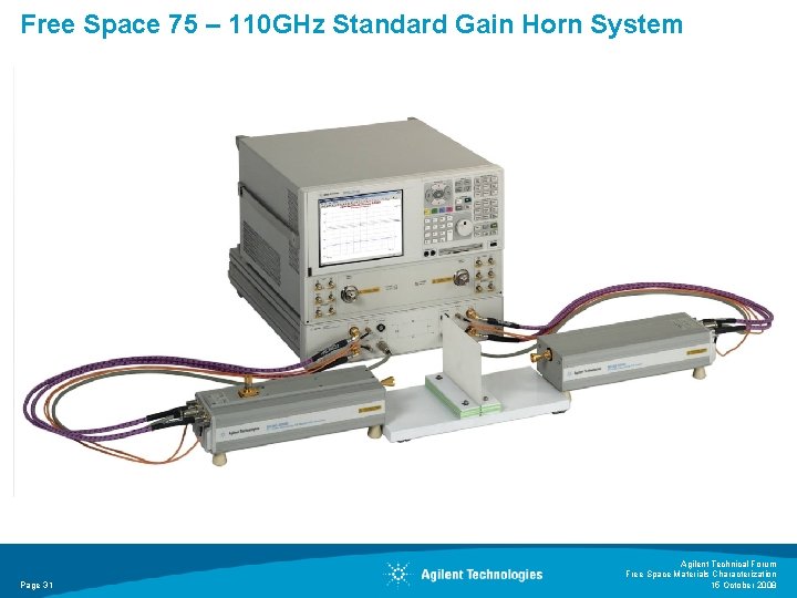
Free Space 75 – 110 GHz Standard Gain Horn System Page 31 Agilent Technical Forum Free Space Materials Characterization 15 October 2008
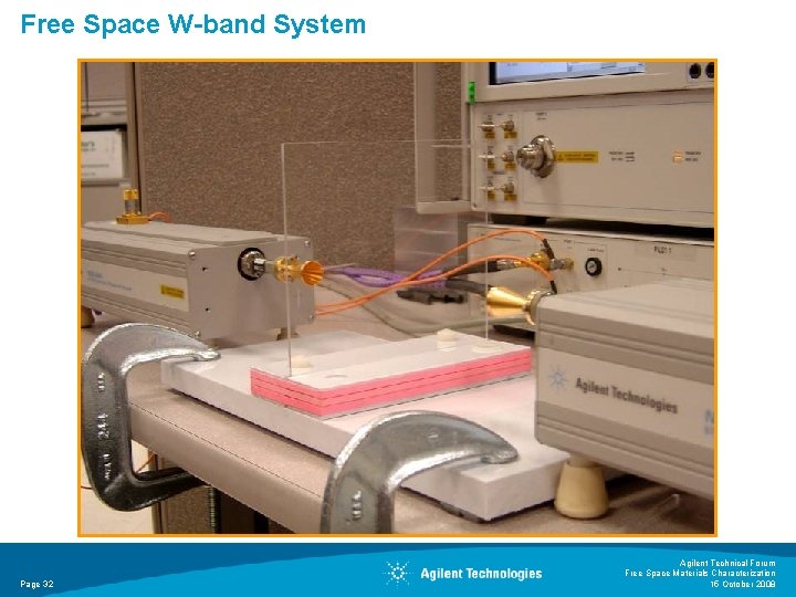
Free Space W-band System Page 32 Agilent Technical Forum Free Space Materials Characterization 15 October 2008
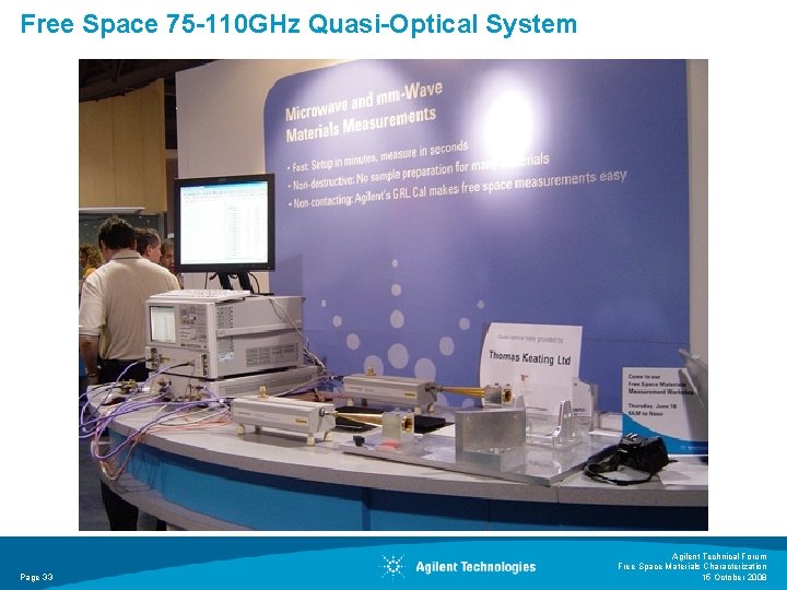
Free Space 75 -110 GHz Quasi-Optical System Page 33 Agilent Technical Forum Free Space Materials Characterization 15 October 2008
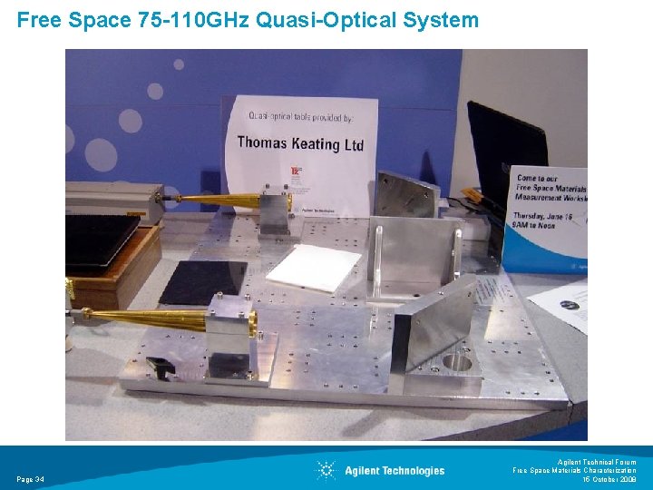
Free Space 75 -110 GHz Quasi-Optical System Page 34 Agilent Technical Forum Free Space Materials Characterization 15 October 2008
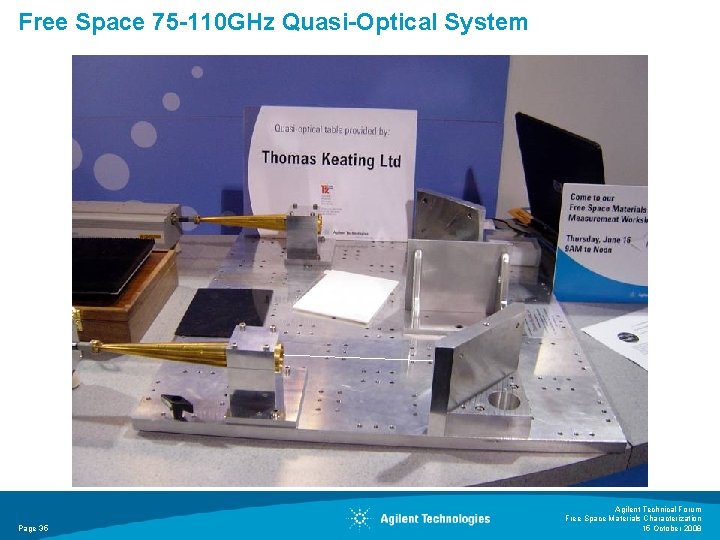
Free Space 75 -110 GHz Quasi-Optical System Page 35 Agilent Technical Forum Free Space Materials Characterization 15 October 2008
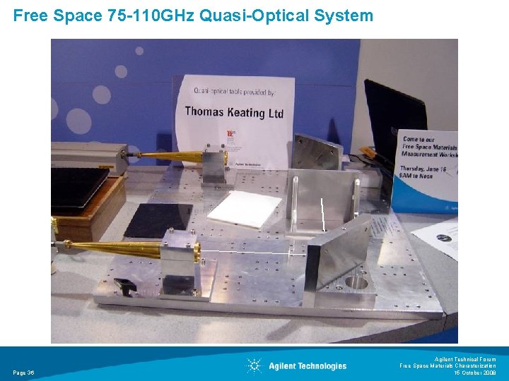
Free Space 75 -110 GHz Quasi-Optical System Page 36 Agilent Technical Forum Free Space Materials Characterization 15 October 2008
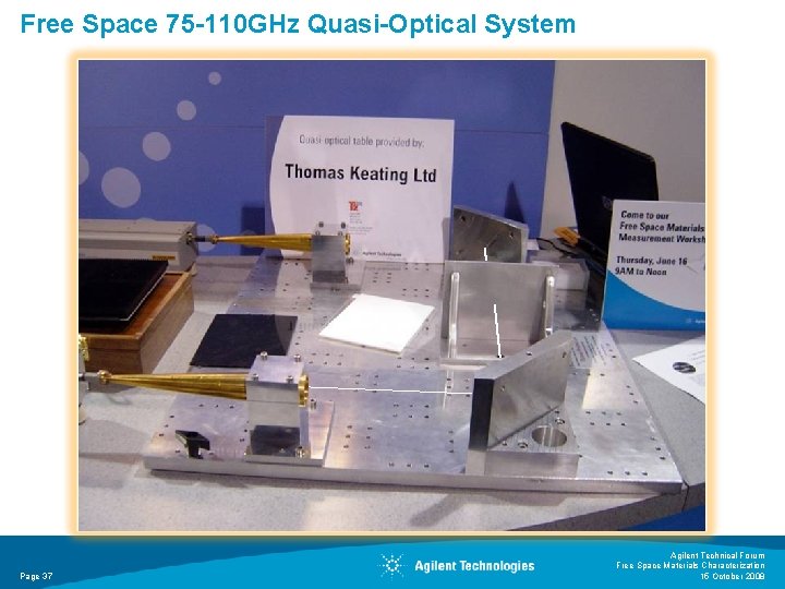
Free Space 75 -110 GHz Quasi-Optical System Page 37 Agilent Technical Forum Free Space Materials Characterization 15 October 2008
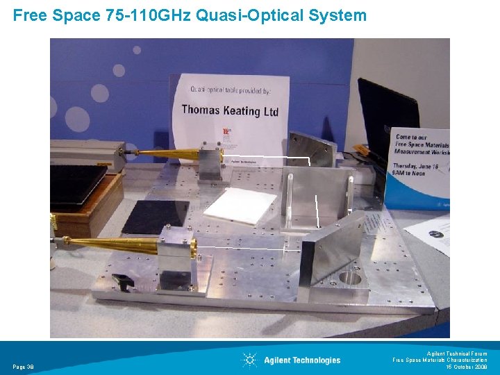
Free Space 75 -110 GHz Quasi-Optical System Page 38 Agilent Technical Forum Free Space Materials Characterization 15 October 2008
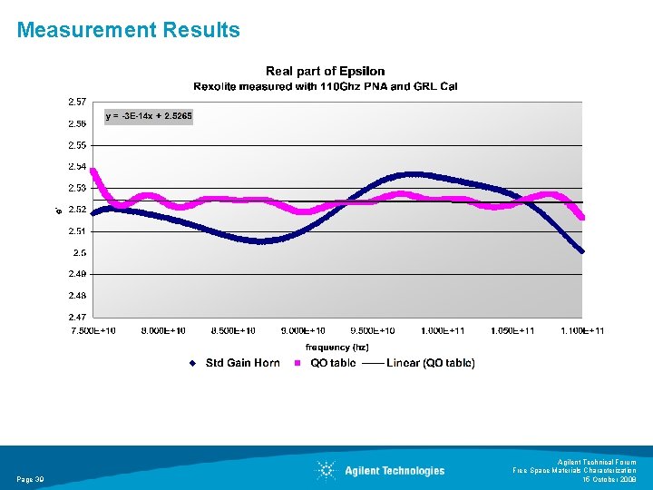
Measurement Results Page 39 Agilent Technical Forum Free Space Materials Characterization 15 October 2008
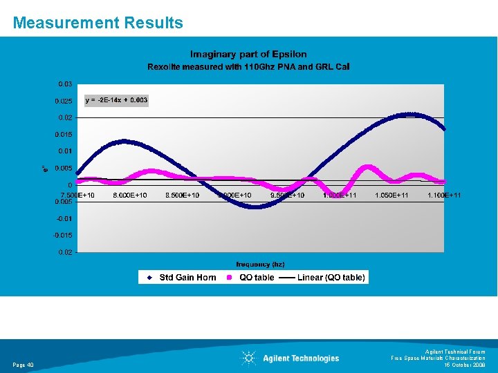
Measurement Results Page 40 Agilent Technical Forum Free Space Materials Characterization 15 October 2008
Conclusion Free Space is a useful method for measuring electromagnetic properties of a of materials. Innovative calibration overcomes challenges of previous free space error correction methods. Page 41 Agilent Technical Forum Free Space Materials Characterization 15 October 2008

For More Information Visit our website at: www. agilent. com/find/materials Page 42 Agilent Technical Forum Free Space Materials Characterization 15 October 2008
References R N Clarke (Ed. ), “A Guide to the Characterisation of Dielectric. Materials at RF and Microwave Frequencies, ” Published by The Institute of Measurement & Control (UK) & NPL, 2003 J. Baker-Jarvis, M. D. Janezic, R. F. Riddle, R. T. Johnk, P. Kabos, C. Holloway, R. G. Geyer, C. A. Grosvenor, “Measuring the Permittivity and Permeability of Lossy Materials: Solids, Liquids, Metals, Building Materials, and Negative-Index Materials, ” NIST Technical Note 15362005 “Test methods for complex permittivity (Dielectric Constant) of solid electrical insulating materials at microwave frequencies and temperatures to 1650°, ” ASTM Standard D 2520, American Society for Testing and Materials Janezic M. and Baker-Jarvis J. , “Full-wave Analysis of a Split-Cylinder Resonator for Nondestructive Permittivity Measurements, ” IEEE Transactions on Microwave Theory and Techniques vol. 47, no. 10, Oct 1999, pg. 2014 -2020 J. Krupka , A. P. Gregory, O. C. Rochard, R. N. Clarke, B. Riddle, J. Baker-Jarvis, “Uncertainty of Complex Permittivity Measurement by Split-Post Dielectric Resonator Techniques, ” Journal of the European Ceramic Society No. 10, 2001, pg. 2673 -2676 “Basics of Measureing the Dielectric Properties of Materials”. Agilent application note. 5989 -2589 EN, April 28, 2005 Page 43 Agilent Technical Forum Free Space Materials Characterization 15 October 2008
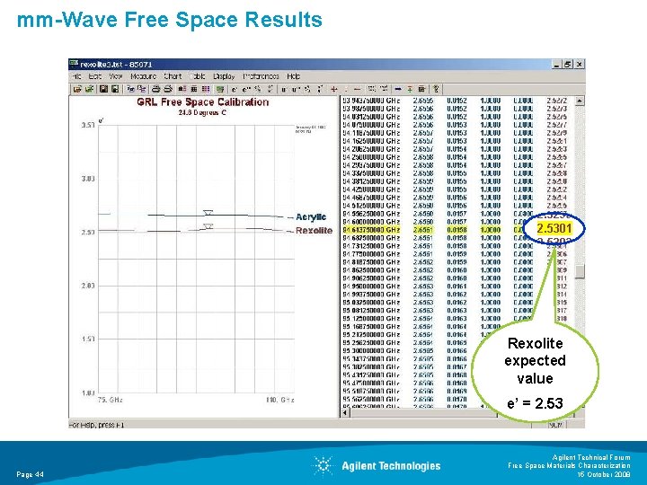
mm-Wave Free Space Results Rexolite expected value e’ = 2. 53 Page 44 Agilent Technical Forum Free Space Materials Characterization 15 October 2008
Apendix • • Section Title Page 45 Agilent Technical Forum Free Space Materials Characterization 15 October 2008
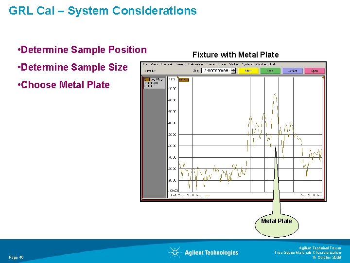
GRL Cal – System Considerations • Determine Sample Position Fixture with Metal Plate • Determine Sample Size • Choose Metal Plate Page 46 Agilent Technical Forum Free Space Materials Characterization 15 October 2008
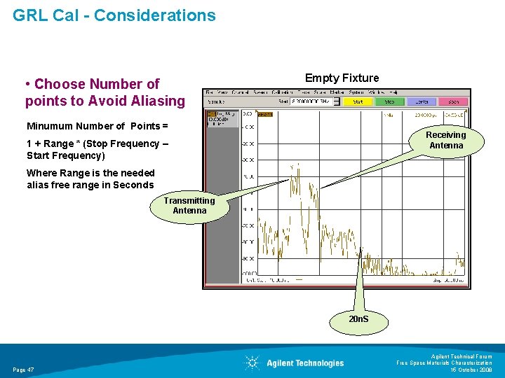
GRL Cal - Considerations • Choose Number of points to Avoid Aliasing Empty Fixture Minumum Number of Points = Receiving Antenna 1 + Range * (Stop Frequency – Start Frequency) Where Range is the needed alias free range in Seconds Transmitting Antenna 20 n. S Page 47 Agilent Technical Forum Free Space Materials Characterization 15 October 2008
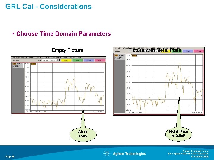
GRL Cal - Considerations • Choose Time Domain Parameters Empty Fixture Air at 3. 5 n. S Page 48 Fixture with Metal Plate at 3. 5 n. S Agilent Technical Forum Free Space Materials Characterization 15 October 2008
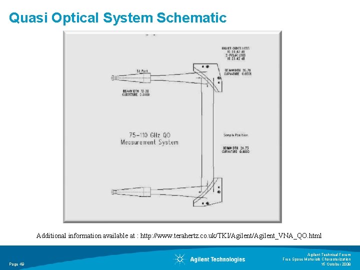
Quasi Optical System Schematic Additional information available at : http: //www. terahertz. co. uk/TKI/Agilent_VNA_QO. html Page 49 Agilent Technical Forum Free Space Materials Characterization 15 October 2008
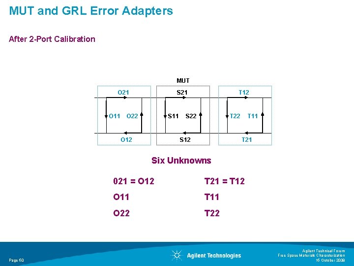
MUT and GRL Error Adapters After 2 -Port Calibration MUT O 21 O 11 S 21 O 22 S 11 O 12 T 12 S 22 T 22 S 12 T 11 T 21 Six Unknowns Page 50 021 = O 12 T 21 = T 12 O 11 T 11 O 22 T 22 Agilent Technical Forum Free Space Materials Characterization 15 October 2008
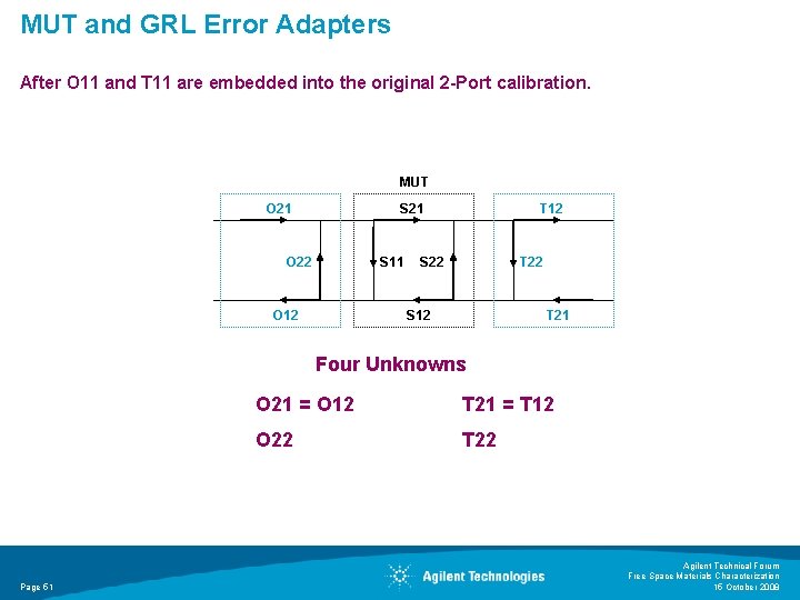
MUT and GRL Error Adapters After O 11 and T 11 are embedded into the original 2 -Port calibration. MUT O 21 S 21 O 22 S 11 O 12 T 12 S 22 T 22 S 12 T 21 Four Unknowns Page 51 O 21 = O 12 T 21 = T 12 O 22 T 22 Agilent Technical Forum Free Space Materials Characterization 15 October 2008
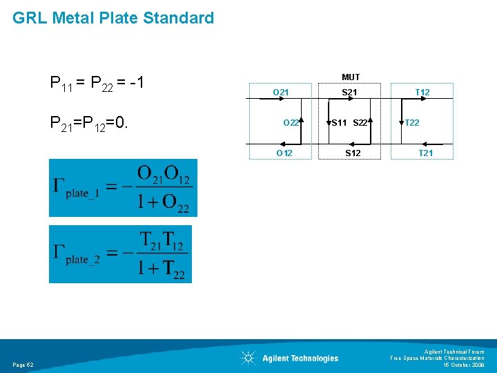
GRL Metal Plate Standard P 11 = P 22 = -1 P 21=P 12=0. MUT O 21 O 22 O 12 Page 52 S 21 S 11 S 22 S 12 T 22 T 21 Agilent Technical Forum Free Space Materials Characterization 15 October 2008
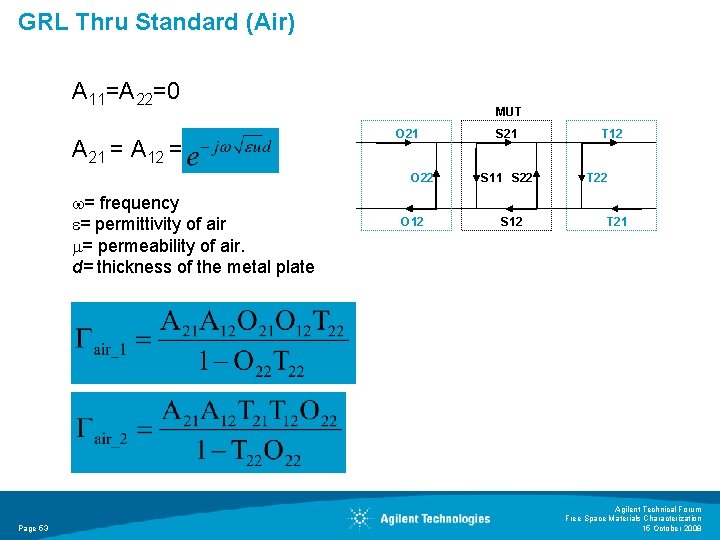
GRL Thru Standard (Air) A 11=A 22=0 A 21 = A 12 = MUT O 21 O 22 = frequency = permittivity of air = permeability of air. d= thickness of the metal plate Page 53 O 12 S 21 S 11 S 22 S 12 T 22 T 21 Agilent Technical Forum Free Space Materials Characterization 15 October 2008
- Slides: 53