Agenda WSB 312 Part 1 Watch the recording

Agenda WS-B 312: Part 1 Watch the recording online • What’s new in SP 1 • How to setup your datacenter networking from scratch WS-B 313: Part 2 Room: Here Time: Now • Software defined networking with VMM • Switch extensibility • Network virtualization

Virtual Machine VM Network • Hyper-V Network Virtualization • Extensible Virtual Switch Subnet 192. 168. 1. 0/24 Extension Fabric Extension Logical NW VLAN 25 Subnet 10. 0/26 Physical Network • • • SR-IOV DHCP Guard IPSec Task Offload Bandwidth Control Trunk Mode

LB Backend Tenant 1 Tenant 2 Management LM, Cluster, Storage

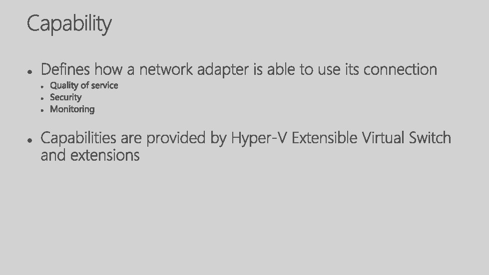
• Add functionality not native to Hyper-V switch • Able to tie virtual to physical network together • Additional tenant isolation capabilities

VM 1 CA 2 CA 1 3 rd Party components VMU VM 2 CA 1 SCVMM Hardware Virtualization Hyper-V Host – Root Partition Capture Extension Filtering Extension Forwarding Extension Physical NIC (SRIOV) Physical NIC (Non SRIOV) Top of rack switch VMM Agent VMM Server Vendor SCVMM Plugin Vendor network management console Policy database

One more type of isolation
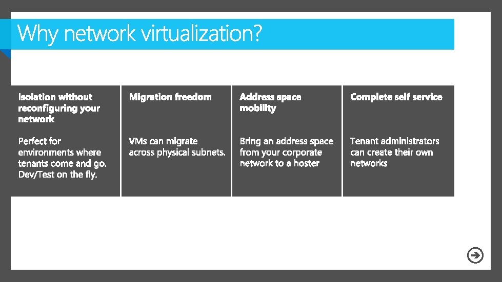

Tenant 3 Tenant 2 Tenant 1 Physical data center Compute Storage Network Virtualization Gateway

192. 168. 2. 22 GRE Key 192. 168. 5. 55 5001 MAC 10. 0. 0. 5 10. 0. 0. 7 192. 168. 2. 22 GRE Key 192. 168. 5. 55 6001 MAC 10. 0. 0. 5 10. 0. 0. 7 192. 168. 2. 22 10. 0. 0. 5 10. 0. 0. 7 Different subnets 192. 168. 5. 55 10. 0. 0. 7 10. 0. 0. 5 10. 0. 0. 7

LB Backend Tenant 1 Tenant 2 Management LM, Cluster, Storage

LB Backend Provider Tenant 1 Tenant 2 Management LM, Cluster, Storage

172. 16. 1. 1, 172. 16. 2. 1 and 10. 254. 1 Network Virtualization Router Contoso datacenter network – 10. 0/16 VMNetwork 1 “Contoso Finance” VM 1 IP: 172. 16. 1. 2 GW: 172. 16. 1. 1 DNS: 172. 16. 3. 99 Subnet 1 172. 16. 1. 0/24 VM 2 IP: 172. 16. 2. 2 GW: 172. 16. 2. 1 DNS: 172. 16. 3. 99 Subnet 2 172. 16. 2. 0/24 Subnet G (hidden) 10. 254. 0/30 DC IP: 10. 0. 0. x VN IP: 10. 254. 2 IP: 172. 16. 0. 2 Gateway “Contoso” DNS 1 IP: 172. 16. 3. 99 CORP-RED 172. 16. 3. 0/24 CORP-KIRK 172. 16. 4. 0/24

Subnet 1 172. 16. 1. 0/24 VM 2 IP: 172. 16. 2. 2 GW: 172. 16. 2. 1 DNS: 172. 16. 3. 99 Subnet 2 172. 16. 2. 0/24 Subnet G (hidden) w. x. y. z/30 Contoso Corp Network VM 1 IP: 172. 16. 1. 2 GW: 172. 16. 1. 1 DNS: 172. 16. 3. 99 IP: 4. 3. 2. 1 DC IP: 10. 0. 0. x VN IP: 10. 254. 2 Internet 172. 16. 1. 1, 172. 16. 2. 1 and 10. 254. 1 Network Virtualization Router Fabrikam Datacenter network – 10. 0/16 VMNetwork 1 “Contoso Finance” IP: 1. 2. 3. 4 NVGRE VPN Gateway “Fabrikam” IP: 172. 16. 0. 2 Any VPN Gateway “Contoso” DNS 1 IP: 172. 16. 3. 99 CORP-RED 172. 16. 3. 0/24 CORP-KIRK 172. 16. 4. 0/24

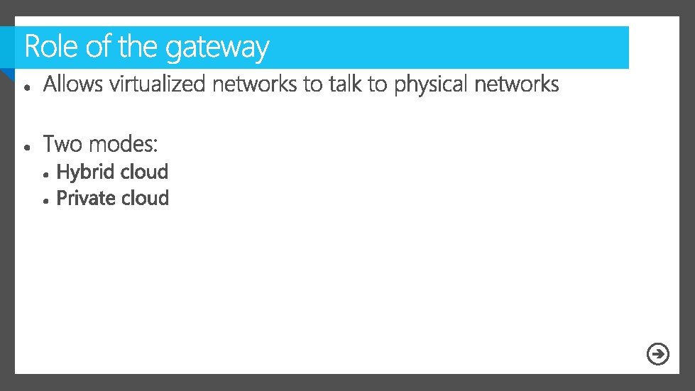
• Private cloud: route to local networks • Hybrid cloud: create site to site tunnel

LB Backend Provider Tenant 1 Tenant 2 Management LM, Cluster, Storage

SD-B 201 IM-B 203 IM-B 308 IM-B 310 WS-B 312 WS-B 313 WS-B 314 WS-B 327

Complete your session evaluations today and enter to win prizes daily. Provide your feedback at a Comm. Net kiosk or log on at www. 2013 mms. com. Upon submission you will receive instant notification if you have won a prize. Prize pickup is at the Information Desk located in Attendee Services in the Mandalay Bay Foyer. Entry details can be found on the MMS website.


Scenarios

VMM 2012 LOGICAL NETWORKS Classify network for VMs to access Map to network topology Allocate to hosts and clouds ADDRESS POOLS LOAD BALANCERS • Allocate a static IP • Apply settings for load • Create IP pool as a • Control load balancer • Create MAC address pool • Create virtual IP templates address to VMs from a preconfigured pool managed range of IP address assignments as a managed range of MAC address assignments balancer capability in service deployment through vendor provider based on Power. Shell consisting of load balancer configuration settings

Internet Data VM to VM

Logical Network “Corp” 1 -M Logical network definition “Building 42” Host group “Production” Physical network adapter 1 -M Subnet. VLAN “ 10. 0/24” “VLAN 5” IP Pool 1 -M “Static. Srv” “ 10. 0. 0. 110. 0. 0. 99” Virtual network adapter Virtual switch
 Specified use")
IP POOLS Assigned to VMs, v. NICs, hosts, and virtual IPs (VIP’s) Specified use in VM template creation Checked out at VM creation —assigns static IP in VM Returned on VM deletion MAC POOLS Assigned to VMs Specified use in VM template creation Checked out at VM creation —assigned before VM boot Returned on VM deletion VIRTUAL IP POOLS Assigned to service tiers that use a load balancer Reserved within IP Pools Assigned to clouds Checked out at service deployment Returned on service deletion

AUTOMATION SUPPORTED BALANCERS Connect to load balancer through hardware provider F 5 BIG-IP Assign to clouds, host groups, and logical networks Citrix Net. Scaler Configure load balancing method and add virtual IP on service deployment Brocade Server. Iron ADX Microsoft Network Load Balancer VIRTUAL IP TEMPLATES Specifies preconfigured properties for configuring a load balancer at service deployment Specifies load balancing methods—round robin, least connections, fastest response

#Create a Logical Network New-SCLogical. Network #Create a network $all. Host. Groups $all. Subnet. Vlan site Get-SCVMHost. Group New-SCSubnet. VLan New-SCLogical. Network. Definition $logical. Network $all. Host. Groups $all. Subnet. Vlan

#Assume $logical. Network and $logical. Network. Definition are set $all. Gateways New-SCDefault. Gateway "10. 0. 0. 1" $all. Dns. Server $all. Dns. Suffixes $all. Wins. Servers "10. 0. 0. 3" “contoso. com” “ 10. 0. 0. 3” New-SCStatic. IPAddress. Pool "My. IPPool" $logical. Network. Definition "10. 0/16" "10. 0. 0. 1" "10. 0. 255. 254" $all. Gateways $all. Dns. Server $all. Dns. Suffixes ""

$ippool Get-SCStatic. IPAddress. Pool "VMTraffic" #Show allocated IP Addresses Get-SCIPAddress, Assigned. To. Type, State $ippool ft -property

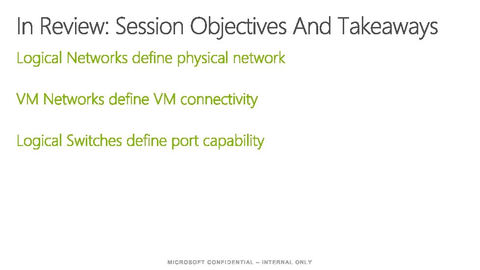
Networking Scenarios Connectivity Capability Multi-tenancy Isolation Mobility Bring your own IP Quality of service (QOS) Security Optimizations Monitors Answer: VM Networks Answer: Logical Switch

Connectivity VM Networks Multi-tenancy Isolation Owner Sharable - Access list Self service creation by Tenant Admin user role No isolation Network virtualization VLAN External Bring your own IP Mobility Enabled by network virtualization Tenant/Customer IP address space separate from Provider IP address space v. NICs only connect to VM Networks are built on logical networks VM Networks span clouds With NV, IP follows VM migration

No Isolation VM Network No Isolation “mgmt” Logical Network “Corp” Logical network definition “Building 42” Subnet. VLAN “ 10. 0/24” “VLAN 5” IP Pool “Static. Srv” “ 10. 0. 0. 110. 0. 0. 99”

Blue VM Physical Server Red VM Virtualization Blue Network Physical Network Red Network
 Blue Corp Red Corp Blue 10. 0.")
Virtualize Customer Addresses Provider Address Space (PA) Blue Corp Red Corp Blue 10. 0. 0. 5 10. 0. 0. 7 Red 10. 0. 0. 5 10. 0. 0. 7 System Center Datacenter Network Virtualization Policy 10. 0. 0. 5 10. 0. 0. 7 CA Blue 192. 168. 4. 11 192. 168. 4. 22 Red 192. 168. 4. 11 192. 168. 4. 22 PA 192. 168. 4. 11 192. 168. 4. 22 Host 1 Host 2 Blue 10. 0. 0. 5 192. 168. 4. 11 10. 0. 0. 7 192. 168. 4. 22 Red 10. 1. 1. 1 192. 168. 4. 11 10. 1. 1. 2 192. 168. 4. 22 Blue 1 Red 1 Blue 2 Red 2 10. 0. 0. 5 10. 0. 0. 7 Customer Address Space (CA)

Hyper-V Network Virtualization VM Network Net. Virt. “Finance” Logical Network “Corp” VM Subnet 192. 168. 0. 0 /16 Logical network definition “Building 42” Subnet. VLAN “ 10. 0/24” “VLAN 5” IP Pool (CA) 192. 168. 0. 2 192. 168. 0. 9 9 IP Pool (PA) “Static. Srv” “ 10. 0. 0. 110. 0. 0. 99”

Hyper-V Network Virtualization Gateways

VLAN VM Network VLAN “Finance” VM Subnet “ 99. 0. 0. 0/24 ” 44 Logical Network Logical network definition Not Connected “Tenant. VLANs “B 42 Tenants ” Subnet. VLAN “ 99. 0. 0. 0/24” “VLAN 44” IP Pool “Static. Srv” “ 99. 0. 0. 199. 0. 0. 99”

External VM Network External “Finance” VM Subnet Logical Network Logical network definition Not Connected “Tenant. Nets” IP Pool “Static. Srv” “ 99. 0. 0. 199. 0. 0. 99” 1 -M “B 27 Tenants ”

#Create Hyper-V NV VMNetwork $logical. Network Get-SCLogical. Network $vm. Network New-SCVMNetwork $logical. Network #Add VMSubnet $subnet New-SCSubnet. VLan $vm. Subnet = New-SCVMSubnet $vm. Network $subnet #. . . etc… #Add IP Pool is same cmdlet as with Logical Network New-SCStatic. IPAddress. Pool $all. Dns. Server $all. Dns. Suffixes $vm. Subnet $all. Gateways

Networking Scenarios Connectivity Capability Multi-tenancy Isolation Mobility Bring your own IP Quality of service (QOS) Security Optimizations Monitors Answer: VM Networks Answer: Logical Switch

Key Tenets Extensible, not replaceable Pluggable switch 1 st class citizen of system Open & public API model Logo certification and rich OS framework Unified Tracing thru virtual switch Benefit Added features don’t remove other features Extensions process all network traffic, including VM-to-VM Live Migration and offloads just work; Extensions work together Large ecosystem of extensions High quality extensions Shorter down times

Extension Extensions are Filters or Windows Filtering Platform Providers Extension state/configuration is unique to each instance of an Extensible Switch on a machine

VMM Management of Switch Extensions CA 1 CA 2 VM 1 VM 2 CA 1 Hardware VMU 3 rd Party components SCVMM Virtualization Root Partition Capture Extension Filtering Extension VMM Server VMM Agent Vendor SCVMM Plugin Forwarding Extension Physical NIC (SRIOV) Physical NIC (Non SRIOV) Top of rack switch Vendor network mgmt console Policy database

3 rd Party Extension Manager Provider Virtual Policy database 1. Import: Logical Networks IP Pools VM Networks Port Profiles 3. Retrieve port Profile policies VMM Switch Extension Manager (VSEM) Provider Interface 2. Set VM Network Port Profile

Host v. NICs VM v. NICs Virtual Switch Instances Physical Host NICs Multiple Windows Server 2012 hosts Uplink p. NIC 1 Uplink p. NIC 2 …on Host 1 Native Switch Settings Uplink p. NIC 1 …on Host 2 Extension 1 Extension 2 Native Switch Settings VM 2 v. NIC 1 Host 1 v. NIC 1 Uplink p. NIC 1 Native Switch Settings Extension 1 Extension 2 VM 3 v. NIC 1 Host 1 v. NIC 2 Uplink p. NIC 2 …on Host 3 Extension 3 VM 1 v. NIC 1 Uplink p. NIC 2 Host 2 v. NIC 2 Uplink p. NIC 2 …etc Extension 1 Extension 2 Native Switch Settings Extension 3 VM 4 v. NIC 1 Host 2 v. NIC 1 Uplink p. NIC 1 VM 5 v. NIC 1 Host 3 v. NIC 1 Extension 2 Extension 3 VM 6 v. NIC 1 Host 3 v. NIC 2 Host 4 v. NIC 1 Host 4 v. NIC 2

Physical Host NICs VMM Switch Infrastructure Uplink p. NIC 1 Uplink p. NIC 2 Host v. NICs VM VS v. NICs Instances Logical Switch Native Switch Settings …on Host 1 VM 1 v. NIC 1 Uplink p. NIC 2 Uplink p. NIC 1 Extension 1 …on Host 2 VM 2 v. NIC 1 Host 1 v. NIC 1 Extension 2 Uplink p. NIC 2 VM 4 v. NIC 1 Host 2 v. NIC 2 Uplink p. NIC 1 Uplink p. NIC 2 Extension 3 …on Host 3 VM 3 v. NIC 1 Host 1 v. NIC 2 Uplink p. NIC 1 …on Host 4 VM 5 v. NIC 1 Host 3 v. NIC 1 VM 6 v. NIC 1 Host 3 v. NIC 2 Host 4 v. NIC 1 Host 4 v. NIC 2

Logical Switch 1 -M Logical switch objects Physical NIC Switch Extensions M - M “Cisco Nexus 1000 v” “In. Mon s. Flow” Uplink Port Profile Set Extension M - M Uplink Port Profile M-1 1 -M “B 42 Switch” Self Service User Port Classificati on “Fast DB” “Web” “Restricted” Cloud 1 -1 Virtual Port Profile Set Extension M - M Virtual Port Profile M-1 1 -M 1 -M v. NIC Native Uplink Port Profile Native Virtual Port Profile

1 -M Logical switch objects Physical NIC Uplink Port Profile Set Logical Switch M-1 1 -M “B 42 Switch” Port Classificati on “Fast DB” “Web” “Restricted” Cloud 1 -1 Virtual Port Profile Set M-1 1 -M 1 -M v. NIC Native Uplink Port Profile Native Virtual Port Profile

Integration Script

- Slides: 66