Agenda 1 What is DMD 2 DLP projector


")


 DMD Panel Condenser")
 Lamp & Reflector a. Output Voltage -")
 UV Cut Filter - UV causes heat")
 Rod Integrator - through internal reflects, it")
 Color Drum & Wheel Optical instrument filtering")
 Illumination Lenses It guides lights from Rod")
 Mirror It changes light path or controls")
 (TIR Prism) Using air gaps between two")
 Projection Lens It transmit Active Area of")

 RGB Segment ( W=1,")


- Slides: 24
Agenda 1. What is DMD? 2. DLP projector 3. - Why should we choice DLP projector? 4. - Optical configurations 5. - Optical elements 6. 3. How it works? 7. - FSC 8. - SCR
1. What is DMD ? DMD: Digital Micromirror Device Beginning to be developed by sight change according to the movement of Rear View Mirror Number of moving parts - 0. 5 (SVGA) to >1. 3 (TBA) million Mechanical motion - - - Makes discrete contacts or landings Lifetime - - - - up to 100, 000 hrs Address voltage - - - - 3. 3 -volt CMOS technology Mechanical elements - - Aluminum Process - - - - Low temperature, sputter deposition, plasma etch (standard SC processes) Package (Type A) - - - Optical, hermetic, welded lid Mirror Address Electrode Yoke Bias/Reset Bus Metal Address Pads Tilting Angle: ± 10˚ ± 12˚
1. What is DMD ? Expressing light and shade by changes of selected light by path Mirror Tilting Expressing Gray level by times taken for path change
2. DLP Projector – Why should we choice DLP projector? Image Quality - Pixelization (fill factor) DLP= ‘Seamless’, Filmlike LCD= Grainy, Pixellated DLP™ = large ‘active’ area LCD = smaller ‘active’ area - Contrast Ratio DLP= simple optics: easier light management LCD= complex optics: more difficult light management - Sharpness (color alignment) DLP= no misalignment LCD= misalignment likely over time DLP™ LCD - Video Quality DLP= fast switching: minimal ‘lag’ (few μs) LCD= slow switching: significant ‘lag’ (tens of ms) smearing for fast moving video
2. DLP Projector – Why should we choice DLP projector? - Color Quality DLP= can match any LCD color gamut LCD= can’t match any DLP color gamut R, G, B Bandwidth is depend on each color because of non-sequential system DLPTM LCD wavelength - Smallest & Brightest DLP= simple optical system, good reflectivity LCD= complex optical system DLPTM LCD
2. DLP Projector – Why should we choice DLP projector? Repeatable Performance (digital accuracy) DLP= digital: precise control, constant performance over time LCD= analog: variable (affected by temperature, vibration, heat, humidity), deterioration over time Reliable - Superior thermal characteristics DLP= reflects heat LCD= absorbs heat, performance degrades - LCD panel degrades as a function of both time and use - DMDs have shown consistent robust performance over time with up to 100, 000 hours lifetime Start LCD DLP
2. DLP Projector – Optical configurations Number of DMD 1 Chip DLP 3 Chip DLP
2. DLP Projector – Optical Configurations TIR prism Non TIR Prism DLP
2. DLP Projector – Optical Configurations TIR prism Non TIR Prism DLP
2. DLP Projector – Optical elements TIR Prism (Total Internal Reflection) DMD Panel Condenser Lens C 3 (Aspherical Surface) Pro Mirror ject i on L Condenser Lens C 2 Condenser Lens C 1 Integrating Rod Reflector (Elliptical Surface) Lamp Aperture Front Glass (UV Cut Coating) Color Drum (R, G, B, W segment) ※Color Wheel ens
2. DLP Projector – Optical elements (1) Lamp & Reflector a. Output Voltage - AC Type : PHILIPS, OSRAM, IWASAKI, THOSHIBA …. - DC Type : USHIO … b. Reflector - Elliptical Type : Almost of all DLP Projector Smallest size= Φ 33 mm, ‘Bami’ lamp made by Philips - Parabolic Type : Used with condensor lens. Some of AV Projector Elliptical Reflector Parabolic Reflector
2. DLP Projector – Optical elements (2) UV Cut Filter - UV causes heat for some parts. (Coating, Plastic, Bonding) - On UV Cut Coating, Try not to make the reflected light be concentrated on one point of UV Lamp Reflected UV light Material: Borofloat + UV Coating
2. DLP Projector – Optical elements (3) Rod Integrator - through internal reflects, it makes uninformative incident light distribution “rectangular uninformative light” Type: Solid Rod – Glass or Plastic Light Tunnel – Mirror in out Avd: good transmission. Strong against heat Dis. Avd: easy to broken, easy to get dust , long Light Distribution from the input Avd: easy to install, dust free, Short Dis. Avd: less transmission, weak for heat Light Distribution from the output
2. DLP Projector – Optical elements (3) Color Drum & Wheel Optical instrument filtering color by Color Filter assembled with Motor < Color Drum > < Color Wheel > < SCR Color Drum >
2. DLP Projector – Optical elements (4) Illumination Lenses It guides lights from Rod Integrator into valid dimensions of DMD L 2 L 1 (m)= h’ / h h h’ θ θ’ = f 2 / f 1 (t)= 2*(f 1+f 2) f 1 f 2 t L 2 L 1 < JT 30 > R 1 R 5 R 4 f 1 = 9. 53, f 2 = 22. 79 ※ m = 2. 39배 R 2 R 3 R 6
2. DLP Projector – Optical elements (5) Mirror It changes light path or controls light position on DMD
2. DLP Projector – Optical elements (5) (TIR Prism) Using air gaps between two prism, it makes selective reflect of transmission in out air gap in air gap <in : reflect, out : transmission> <in : transmission, out : Reflect > TIR Prism DMD Panel
2. DLP Projector – Optical elements (5) Projection Lens It transmit Active Area of DMD on Screen Fixed Focus Lens – Cannot control the zoom in Fixed distance Variable Focus Lens (Zoom Lens) – Can control the screen size with zoom in Fixed distance Used in DLP Engine with TRI Prism DMD Screen < Converging Type Zoom Lens > Screen Telecentric Type Zoom Lens> DMD < Used DLP Engine with Non-TIR Prism
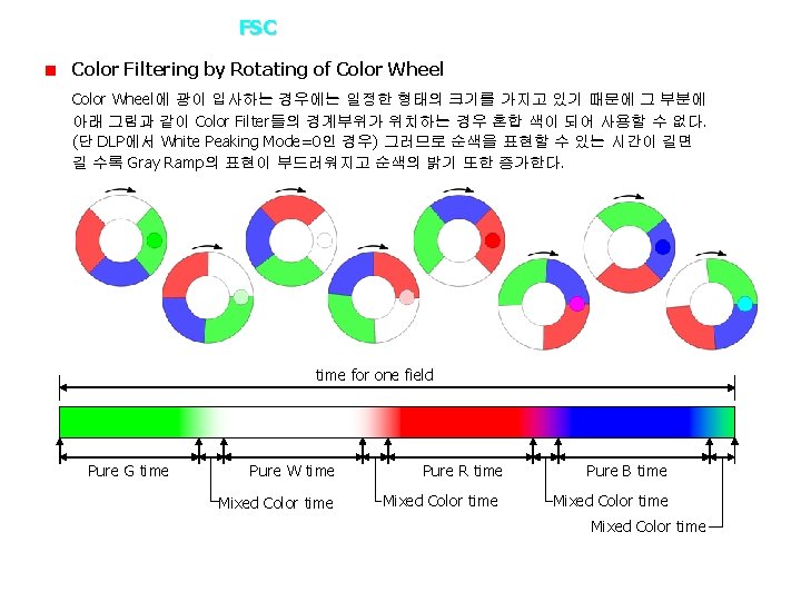
3. How it works? – FSC Operation ※FSC=Field Sequential Color Lighting on DMD in timely sequence In case of transmitting Red Filter, Green and Blue is reflected and is useless Blue and Green light turned into heat Color Wheel Red light transmitted 33% efficiency
3. How it works? – FSC Brief Brightness Estimation 1) RGB Segment ( W=1, R: G: B Intensity= 1/3, R: G: B segment size= 1: 1: 1) R = 1/3 G = B = 1/3 RGB size = 1/3 : Wo = R/3 + G/3 + B/3 = 0. 333 2) RGB Segment ( W=1, R: G: B Intensity= 1/3, R: G: B: W segment size= 1: 1: 1: 1) R = 1/3 G = B = 1/3 W=1 RGB size = 1/4 Wo = R/4 + G/4 + B/4 + W/4 = 0. 500
3. How it works? – SCR Operation ※SCR= Sequential Color Recapture Scroll Lighting Whole RGB on DMD in timely sequence Integrating RGB색이 반사된 RGB Filter에 CMY색은 투과하고 Rod의 Rod에 의해 Integrating CMY색은 출사측에 입사된 CMY색은 백색광은 해당 Color 반사되어 Rod의 RGB색을 Filter가 입사측의 RGB Integrating Segment 위치하며, 투과되고 Mirror면에 Filter에 나머지 출사면의 의해 입사측으로 의해 RGB색은 다시 Size안에 해당 RGB 다시 되돌아간다. RGB색은 RGB Filter에 반사된다. Segment를 투과된다. 입사하게모두 된다. 포함한다 Reflected RGB is re-reflected by Integrating Rod INRod의 and transmitted by RGB Filter
3. How it works? – SCR Brief Brightness Estimation Integrating Rod : Total size vs Hole Size ratio = 0. 5 Total size Input vs Hole Input Intensity Ratio = 0. 85 1) RGB Segment ( Wi=1, R: G: B Intensity= 1/3, R: G: B segment size= 1: 1: 1) 2) 3) 4) R = first transmission R(0. 85*1/3) + G, B reflected MY of re-reflected R(0. 85*0. 5*2/3*1/3*2) = 0. 472 G, B is same as above G=B= 0. 472 5) RGB size = 1/3 Wo = R/3 + G/3 + B/3 = 0. 472 2) RGB Segment ( W=1, R: G: B Intensity= 1/3, R: G: B: W segment size= 1: 1: 1: 1) R = first transmission R(0. 85*1/3) + G, B reflected MY of re-reflected R(0. 85*0. 5*2/4*1/3*2) = 0. 425 G, B is same as above G = B = 0. 425 W=1 RGB size = 1/4 Wo = R/4 + G/4 + B/4 + W/4 = 0. 569