Advanced Turning Unit 047 Taper turning How COMPOUND


")


, the name cermet combines the words")


")
 What are the Benefits of Ti. N Coating?")


 with the")


- Slides: 50
Advanced Turning, Unit 047
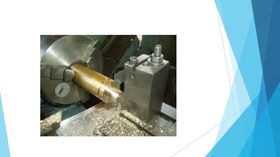
Taper turning, How? COMPOUND SLIDE / TOP SLIDE TAPER
Taper turning Compound / top slide method Advantages: This method allows both external and internal angles to be produced. No limitations to the angle produced Disadvantages: The limitations of this method is that the length of taper is limited to the length of travel of the compound slide. The compound slide, being hand operated, needs skill to produce a constant feed rate resulting in a good surface finish.
Taper turning OFFSET TAILSTOCK METHOD TAPER
Taper turning Offset tailstock method Advantages The length of work is only limited by the distance between the headstock and tailstock, and the feed can be by power traverse. Disadvantages The limitation of this method is that only shallow tapers may be turned, due to the amount of offset available on the tailstock. Only external tapers can be turned by this method.
Taper turning • Taper turning attachment TAPER TURN 1 TAPER 2
Taper turning attachment TAPER
• The three-jaw chuck is self centring. The jaws are moved centrally by a flat scroll • The chuck is usually equipped with two sets of hardened jaws, for holding external and internal work. • A third set can be purchased which are not hardened, these are called soft jaws. • The chuck is used to hold bright drawn material or previously machined work. In either case the work must be round, triangular or hexagonal. • The work should not be removed from the chuck until all the operations required have been carried out. • Once work is removed from the chuck it cannot be guaranteed to run concentric if replaced in the chuck. 3 jaw chuck
3 jaw chuck jaws External jaws Standard jaws (Internal)
• With the four-jaw chuck each of the four jaws is moved independently by a threaded screw. • The jaws are reversible so that they can be used for either very small or very large diameter work. • The chuck is more heavily constructed than the three-jaw and has a much greater gripping power. • Because of the four jaws, the chuck can hold both symmetrical and irregularly shaped work. • The work-piece may be set to run either concentric or offset to run eccentrically. 4 jaw chuck
Soft jaws Soft soft 19
How is the chuck size determined? Outside diameter of the chuck body
Face plate FACE
Work holding - Steady STEADY Fixed Steady – Used to support long slender work. Bolted to the lathe bed. Contains 3 adjustable work supports.
Work holding - Steady T STEADY Travelling steady – • Fixed to the saddle so it can travel along the work-piece with the tool. • Contains 2 adjustable work supports, the tool acts as the 3 rd support. • Supporting long slender work-pieces close to the cutting tool when turning to a diameter
Thread chasing dial. The thread chasing dial is used for threading. • The thread chasing dial works off the leadscrew and is used as a tracking device. • The dial tells you when to engage the half nut lever so the tool follows the same thread groove every time. TCD https: //www. youtube. com/watch? v=yq. Yd 2 -52 R 5 U
Capstan / turret lathe. • Used for mass production. • Two tool-posts, front generally used for turning operations, rear usually used for part off. • No tailstock, drills, reamers etc mounted on a turret which indexes around. • Work held in collet chuck. PO LATHES
Core drill. Used to open out existing holes, cannot be used for starting a hole.
Carbide cutting inserts. Material groups
DCGT • • D=55° rhomboid, C= 7° clearance, G= tolerance of insert T= with hole, chip breaker one side
DNMG • • D= 55° rhomboid, N= 0° clearance, M= tolerance G= with hole, chip breaker both sides,
CCMT • • C= 80° rhomboid, C= 7° clearance, M= tolerance T= with hole, chip breaker one side,
TCGT • • T= Triangle, C=7° clearance, T= tolerance G= with hole, chip breaker one side.
CNMG • • C= 80° Rhomboid, N= 0° clearance, M= tolerance G= with hole, chip breaker both sides.
VBMT • • V= 35° Rhomboid, B= 7° clearance, M= tolerance T= with hole, chip breaker one side.
3 th Letter • The 3 rd letter in tip designation, i. e. DNMG designates the tolerance class the tip has been made to. • The letter indicates the tolerances that control the indexability of the insert. • Tolerances specified do not imply the method of manufacture. • The tolerance applies to the inscribed circle within the insert.
What is a Cermet? Type of insert (tip), the name cermet combines the words ceramic and metal. What is it used for? CERMET
Cermets also feature higher hot hardness than carbide, meaning they maintain more wear resistance at high temperatures. As a result, cutting speeds can often be increased with these tools without compromising tool life. Cermets today are tougher than they once were, but their toughness still does not match that of the toughest carbides. Cermets are not appropriate for roughing. Typical applications are finishing in stainless steels, cast irons, low carbon steels and ferrous steels. They can perform quicker than carbide. Typical cutting speeds: 150 - 350 m/min.
What is “CBN” ? A form of industrial diamond called “Cubic Boron Nitride” Uses? Cubic boron nitride is used for machining very hard ferrous materials such as steel dies, alloy steels and hard-facing materials.
What is “PCD“ in cutting tool terms? A form of industrial diamond called “Polycrystalline diamond”. Uses? Polycrystalline diamond is used for non-ferrous machining and for machining abrasive materials such as glass and some plastics.
Titanium Nitride coated cutters. (Ti. N)
Titanium Nitride coated cutters. (Ti. N) What are the Benefits of Ti. N Coating? • Provides increased surface hardness: Ti. N coating protects against abrasion and provides protection against the damaging effects of heat. • Provides increased durability: The hard, heat resistant Ti. N coating prolongs durability by protecting the tool material. • Provides wear resistance: Since the extremely hard coating transfers far less heat than an uncoated part, the wear resistance is greatly increased, providing a much greater part life. • Provides higher lubricity: The coefficient of friction of Titanium Nitride is very low. This provides for quicker chip dissipation, less heat build up, and a superior workplace finish.
Form tools - Turning • Generally made from HSS as it is easier to grind to whatever shape you require.
Rake angles:
Rake angle Is provided for ease of chip flow and overall machining. Positive rake – helps reduce cutting force and thus cutting power requirement. Negative rake – to increase edge-strength and life of the tool Zero rake – to simplify design and manufacture of the form tools.
Cutting-Tool Terms Relief or Clearance angle: Ground on the end and side faces of a tool to prevent it from rubbing on the work piece. To enable only the cutting edge to touch the work piece. Side Relief angle: • Angle ground directly below the cutting edge on the flank of the tool End Relief angle: • Angle ground from the nose of the tool 37
Clearance angle is essentially provided to avoid rubbing of the tool (flank) with the machined surface which causes loss of energy and damages of both the tool and the job surface. Hence, clearance angle is a must and must be positive (3 o ~ 15 o depending upon tool-work materials and type of the machining operations like turning, drilling, boring etc. )
Rake angles on HSS tools. • High / Medium / Low or none: • • • Mild steel ? Brass / Bronze ? Aluminium ?
• Mild steel - Medium • Brass / Bronze - Low or zero • Aluminium - High
Suggested rake angles
Carbide tools can be up to 2 – 5 faster than HSS, depending on the grade and manufacturer, what examples did you find?
Manganese • Manganese improves machinability, helping the chip to break. • Manganese is also added to steel to improve hot working properties and increase strength, toughness and hardenability.
Power used while cutting is a formula that can be used to find out how much power is being used whilst machining. The formula is: Pc = vc x f x ap / 25 (k. W) Where: • Pc = • vc = • f= • ap = power used in cutting surface speed in m/min feed per revolution depth of cut in mm
The formula is Pc= power vc cutting speed x f feed per rev x ap depth of cut / 25 (k. W) kilowatt • Turning aluminium with a HSS tool at a feed of 0. 3 mm per revolution and a depth of cut of 3 mm = • 70 x. 3 x 3 / 25 = 2. 52 kw • Turning low carbon steel with a HSS tool at a feed of 0. 1 mm per revolution and a depth of cut of 1 mm = • 30 x. 1 x 1 / 25 = 0. 25 kw • Turning stainless steel with a HSS tool at a feed of 0. 1 mm per revolution and a depth of cut of 2 mm = • 20 x. 1 x 2 / 25 = 0. 16 kw
Measuring a taper using steel balls taper
Extra question, try to find what the standard spacing of the spindle speed ratios on a centre lathe is? Is it a. Linear progression b. Random c. Geometric progression d. Radial The answer is geometric! GP
Geometric Sequences • A geometric sequence goes from one term to the next by always multiplying (or dividing) by the same value. So 1, 2, 4, 8, 16, . . . and 81, 27, 9, 3, 1, 1/3, . . . are geometric, since you multiply by 2 and divide by 3, respectively, at each step.
Balancing
Re-cap What are the 3 way to turn a taper on a lathe? Compound slide / offset tail stock / taper turning attachment Three types of jaws on a 3 jaw chuck Internal / external / soft How is the chuck size determined? Outside of the chuck What is the back tool post for on a turret lathe Part off tool What is meaning of the first 4 letters in the ISO tip designation? Shape / relief angle / tolerance / hole and chip breaker The most suitable surface speed for machining mild steel using a high speed steel (workshop calculation)