
Advanced Manufacturing Processes MEC 6240 Syllabus General classification

Advanced Manufacturing Processes (MEC 6240)
Syllabus General classification of unconventional machining processes; Abrasive jet machining; Water jet machining; Abrasive water jet machining; Magnetic abrasive jet machining; Ultrasonic machining; Chemical machining; Electro- chemical machining; Electric discharge machining; Electron beam machining; Laser beam machining; Ion beam machining; Plasma arc machining; Comparative evaluation of different processes. References: 1. Modern Machining Processes by Pandey and Shah, Tata Mc. Graw Hills. 2. Non-Traditional Manufacturing Proceses by Gary F. Benedict, Marcel Dakker. 3. Non-Conventional machining by P. K. Mishra, Narosa. 4. Principals of Electro-chemical Machining by J. A. Mcgeough, Chopman & Hall, London. 5. Manufacturing Science by Amitabha Ghosh & Asok Kumar Mallik East. West press Private limited. 2
Course Outcomes 1. Ability to identify methods and the respective process parameters to machine components using chemical and electro-chemical energy. Capability to estimate them. 2. Able to identify methods and the respective process parameters to machine using electrical energy. Capability to estimate them. 3. Gain the knowledge and able to employ various methods, tools and equipments to machine a component with high power density. Capable to estimate the process variables. 4. Capability to estimate process parameters and employ mechanical energy in machining components. 3
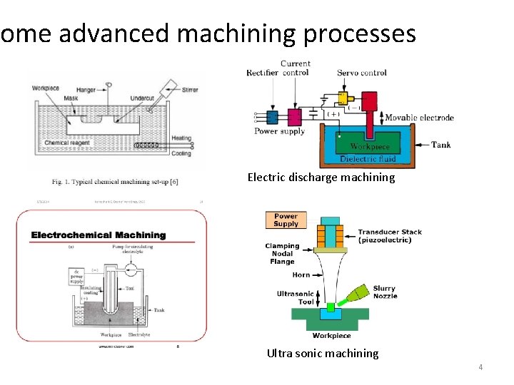
ome advanced machining processes Electric discharge machining Ultra sonic machining 4
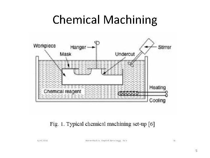
Chemical Machining 5
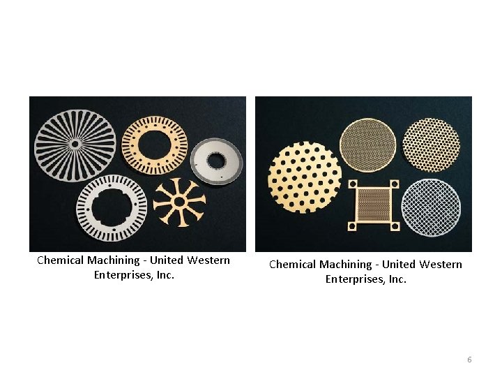
Chemical Machining - United Western Enterprises, Inc. 6
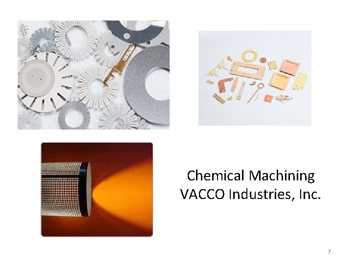
Chemical Machining VACCO Industries, Inc. 7
Chemical Machining • Also referred to as chemical milling • Uses chemicals • to extract or remove unwanted metal for a metal surface • Utilized when • other more traditional methods are – either unable to easily perform the task – or the desired final product is too intricate – or complex to complete • Often used for application – where precise is vital – such as micro components – or in the electronics field where traditional machining processes could damage the surface and overall product. 8
• Chemical machining is very precise • as the areas that are desired to remain are protected from the chemicals • which insure that only unwanted metal is removed. • This form of manufacturing is used • for a number of different industries – – • from the aerospace industry to the automotive industry Chemical machining • since the nineteenth century • pretty simple • the surface is cleaned • the desired patterned is masking out – leaving only the parts that are to be etched exposed • the metal surface is lowered into a chemical solution • The chemical eats away at the exposed metal 9
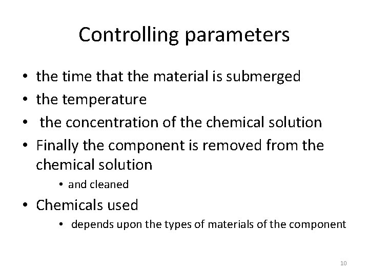
Controlling parameters • • the time that the material is submerged the temperature the concentration of the chemical solution Finally the component is removed from the chemical solution • and cleaned • Chemicals used • depends upon the types of materials of the component 10

11
12

13
14
15
16
17
18
19
20
21
22
23
24
Photo Chemical Machining Process (PCM)
• A chemical milling process • Uses • a photo resist – a photosensitive resist which, when exposed to light, loses its resistance or its susceptibility to attack by an etchant or solvent. Such materials are used in making microcircuits. » polyhydroxystyrene-based polymers » mixture of diazonaphthoquinone (DNQ) and novolac resin (a phenol formaldehyde resin). • and etchants • To corrosively machine away selected areas 26
Examples of PCM products 27
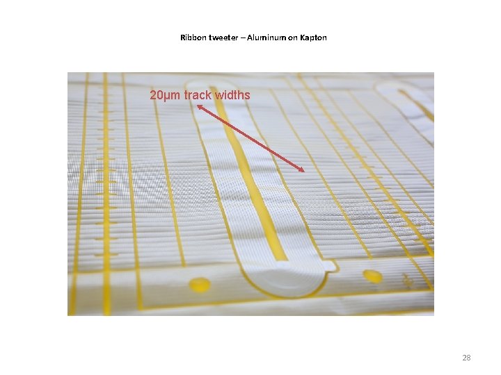
Ribbon tweeter – Aluminum on Kapton 20µm track widths 28
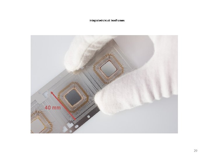
Integrated circuit leadframes 40 mm 29
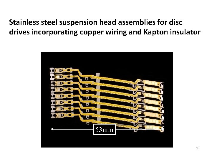
Stainless steel suspension head assemblies for disc drives incorporating copper wiring and Kapton insulator 53 mm 53 mm 30
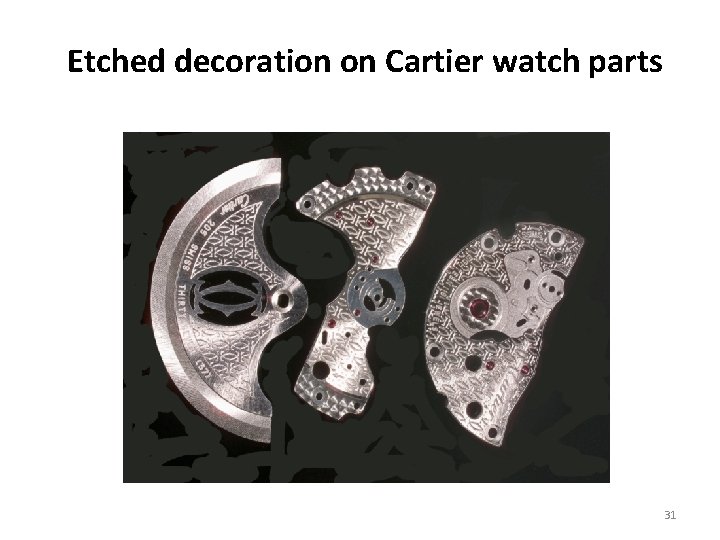
Etched decoration on Cartier watch parts 31
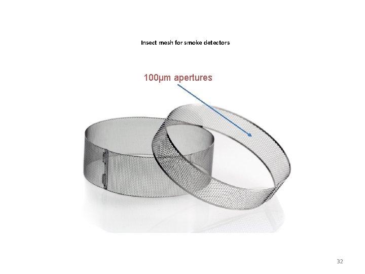
Insect mesh for smoke detectors 100µm apertures 32
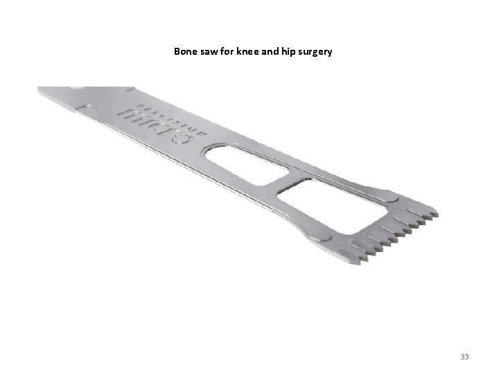
Bone saw for knee and hip surgery 100µm apertures 33
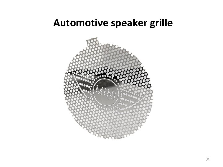
Automotive speaker grille 34
Other PCM products • Perforated products such as: • Grids, filters, meshes, screens, masks and attenuators. • Complex geometry products such as: • Shims, gaskets, levers, diaphragms, washers, springs, links, brackets, connectors, probes, heat sinks and exchangers, lead frames, rotor and stator laminations, shutter blades, iris leaves, graticules, masks, encoder discs, jewellery. • Surface-etched products such as: • Rules, scales, clutch plates, emitter contacts, bearings, edge filters, hybrid circuit pack lids, boxes and enclosures, nameplates, decorative plaques, components etched with permanent logos, trademarks, part numbers or instructions. 35
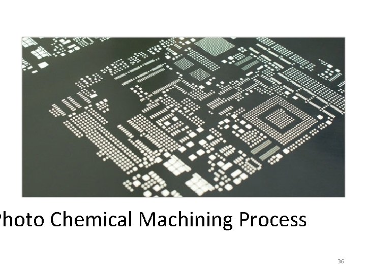
Photo Chemical Machining Process 36
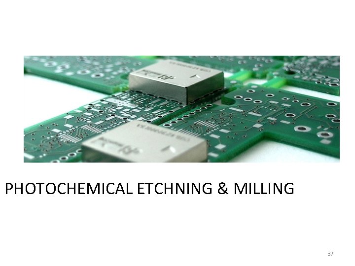
PHOTOCHEMICAL ETCHNING & MILLING 37
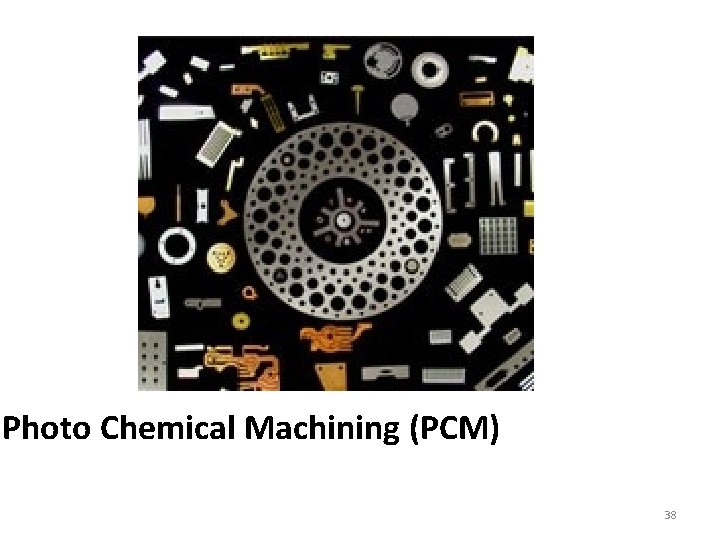
Photo Chemical Machining (PCM) 38
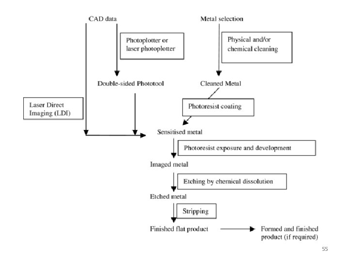
Designing PCM Products with CAD • The engineering drawing is digitised to produce data streams that can be utilised to produce either: • a conventional high resolution phototool via a photoplotter or • instructions to drive a laser to expose photoresist –coated metal directly (known as Laser Direct Imaging or LDI) 39
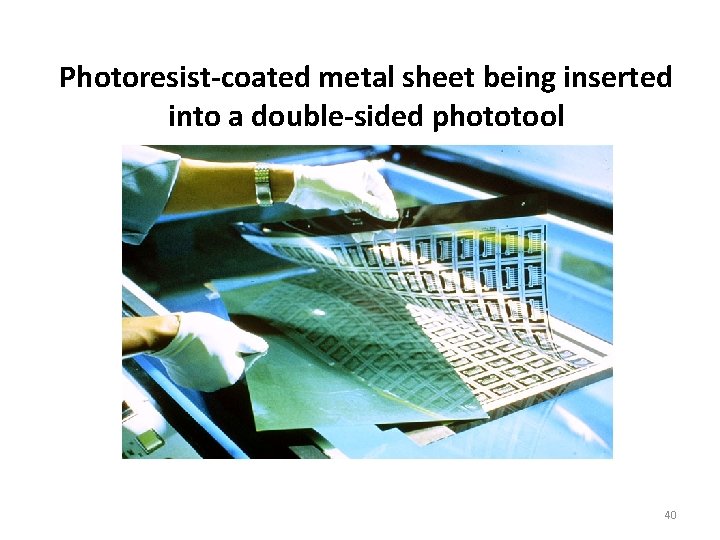
Photoresist-coated metal sheet being inserted into a double-sided phototool 40
What is the purpose of a photoresist? • A photoresist - a uv photosensitive polymer supplied as a liquid or dry film - is used to produce an image on metal. Where the photoresist has been exposed to uv radiation, it becomes insoluble in a developer solution and adheres strongly to the metal surface to form an etchant-resistant coating. 41
Coating The objective of photoresist coating is to provide a protective surface stencil that can protect from (resist) the action of chemical etching. The stencil pattern is achieved by photo-exposure of the light-sensitive coating via uv flood exposure through a phototool or uv laser exposure (also known as laser direct imaging or LDI). 42
Resolution v. coating thickness In general, liquid photoresists will give coating thicknesses between 2 m and 15 m. Dry film photoresist thicknesses are generally between 10 m and 100 m. The finest features will be resolved in the thinnest photoresists but the stencil gains increased strength with thicker coatings. Note the compromise 43
Liquid photoresists Solvent and aqueous photoresists can be applied by: Spinning (high speed) or Whirling (low speed) Dipping (the method most commonly used) Spraying Flowing Roller coating and for conductive (largely aqueous) systems Electrophoretic coating 44
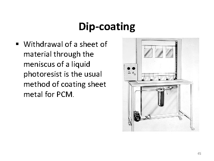
Dip-coating Withdrawal of a sheet of material through the meniscus of a liquid photoresist is the usual method of coating sheet metal for PCM. 45
Dry film photoresists can be applied by hot lamination and the images developed by: Aqueous solutions (predominant in the 21 st century) Semi-aqueous solutions (an environmental development of the 1970 s) Solvents (the original technology of 1960 s) 46
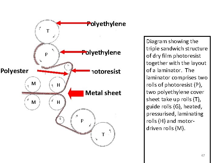
Polyethylene T Polyethylene P Polyester Photoresist M H Metal sheet M H P T Diagram showing the triple sandwich structure of dry film photoresist together with the layout of a laminator. The laminator comprises two rolls of photoresist (P), two polyethylene cover sheet take up rolls (T), guide rolls (G), heated, pressurised, laminating rolls (H) and motordriven rolls (M). 47
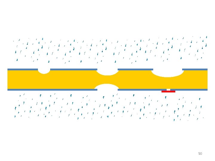
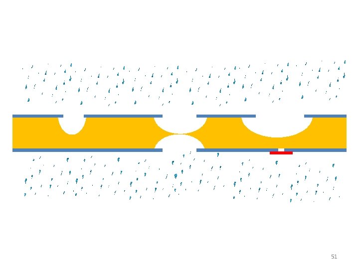
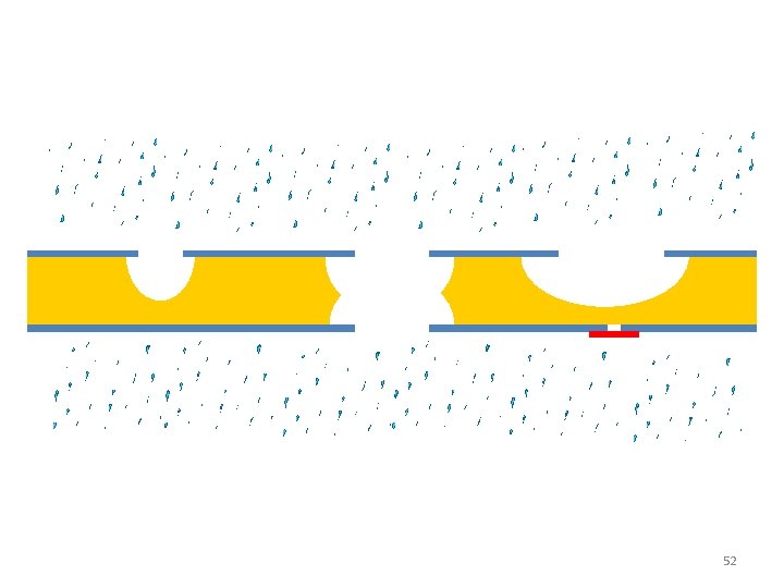
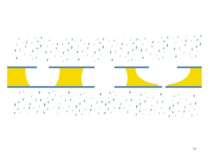
The PCM Production Process • Once the photoresist has been imaged to produce an etchant –resistant patterned coating, chemical etching is used to transfer that pattern into the metal by selective removal as shown in the following animation. 48
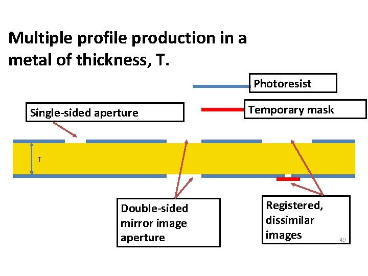
Multiple profile production in a metal of thickness, T. Photoresist Single-sided aperture Temporary mask T Double-sided mirror image aperture Registered, dissimilar images 49
50
51
52
53
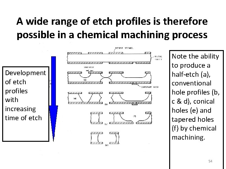
A wide range of etch profiles is therefore possible in a chemical machining process Development of etch profiles with increasing time of etch Note the ability to produce a half-etch (a), conventional hole profiles (b, c & d), conical holes (e) and tapered holes (f) by chemical machining. 54
55
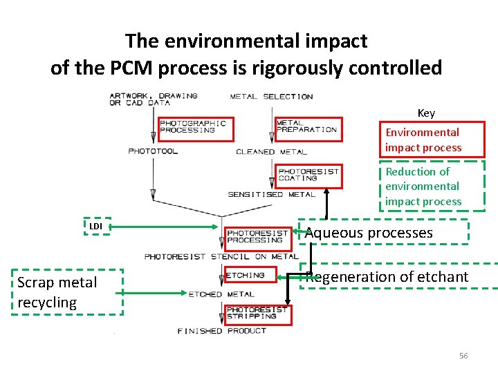
The environmental impact of the PCM process is rigorously controlled Key Environmental impact process Reduction of environmental impact process LDI Scrap metal recycling Aqueous processes Regeneration of etchant 56
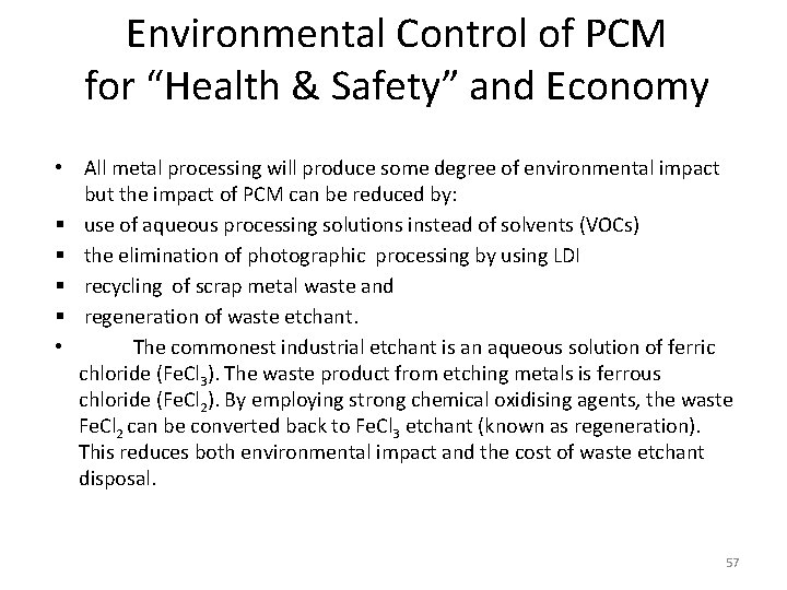
Environmental Control of PCM for “Health & Safety” and Economy • All metal processing will produce some degree of environmental impact but the impact of PCM can be reduced by: use of aqueous processing solutions instead of solvents (VOCs) the elimination of photographic processing by using LDI recycling of scrap metal waste and regeneration of waste etchant. • The commonest industrial etchant is an aqueous solution of ferric chloride (Fe. Cl 3). The waste product from etching metals is ferrous chloride (Fe. Cl 2). By employing strong chemical oxidising agents, the waste Fe. Cl 2 can be converted back to Fe. Cl 3 etchant (known as regeneration). This reduces both environmental impact and the cost of waste etchant disposal. 57

Competing technologies: the designer needs to choose the lowest-cost manufacturing process that also meets the technical specifications of the product 58
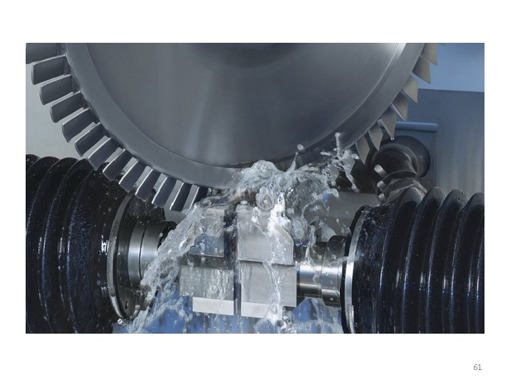
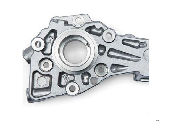
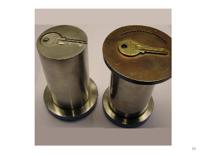
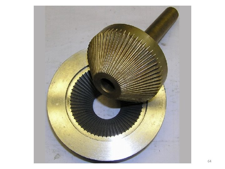
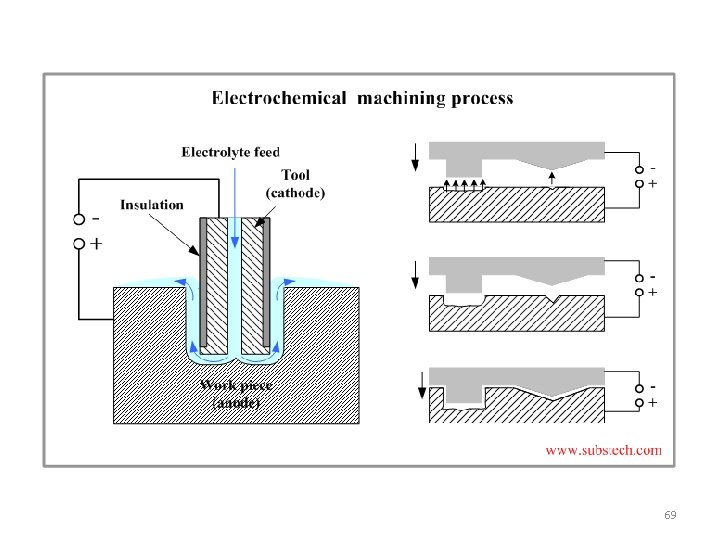
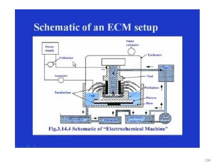
Electro-Chemical Machining Process (ECM) 59
60
61
62
63
64
Advantages • Low-level tool wear (cathode), an ideal precondition for batch production • Surface finishes – Up to Ra 0. 05 • Precision machining • No thermal and mechanical effects – therefore, no changes in the material properties • Hardness, toughness and magnetic qualities of the material remain unchanged • Possibility to machine diminutive and thin-walled contours • A high degree of repeat accuracy in the machining of the surface structure • Simple but highly efficient production process – no need for subsequent deburring or polishing • Rough-machining, finish-machining and polishing in a single operation 65
Disadvantages • High energy consumption. • Non conducting material cannot be machined. • Corrosion and rust of ECM machine can be hazardous – But preventive measures can help in this regard. 66
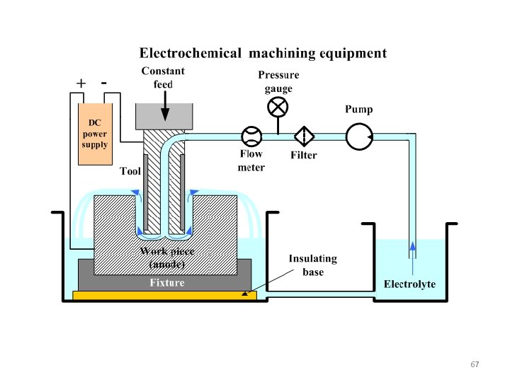
67
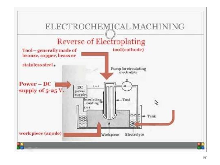
68
69
70
71
72
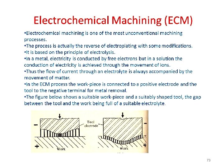
73
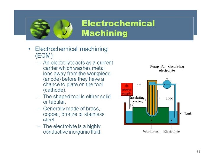
74
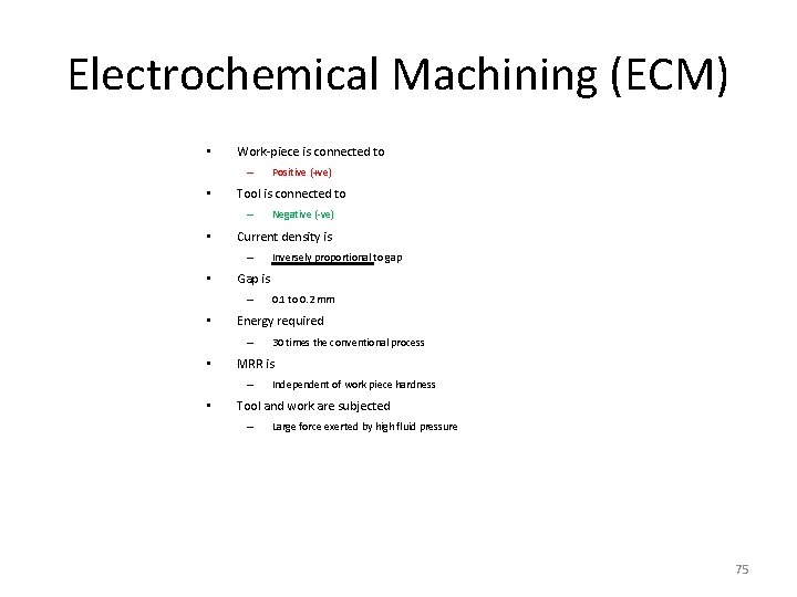
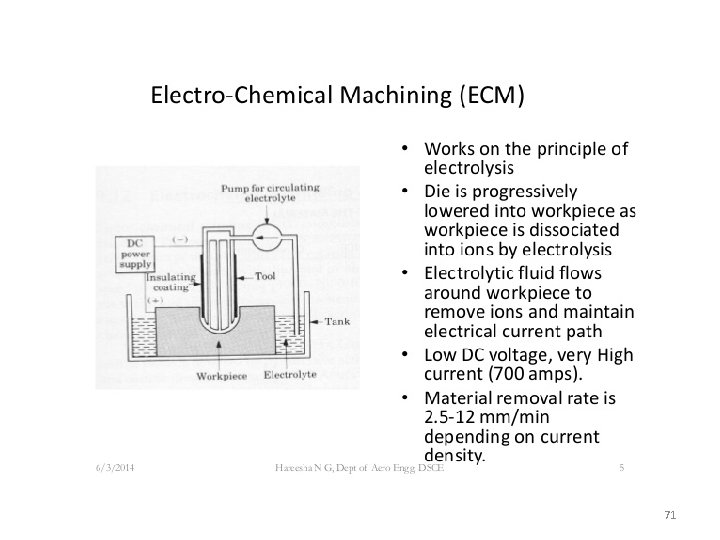
Electrochemical Machining (ECM) • Work-piece is connected to – • Tool is connected to – • 30 times the conventional process MRR is – • 0. 1 to 0. 2 mm Energy required – • Inversely proportional to gap Gap is – • Negative (-ve) Current density is – • Positive (+ve) Independent of work piece hardness Tool and work are subjected – Large force exerted by high fluid pressure 75
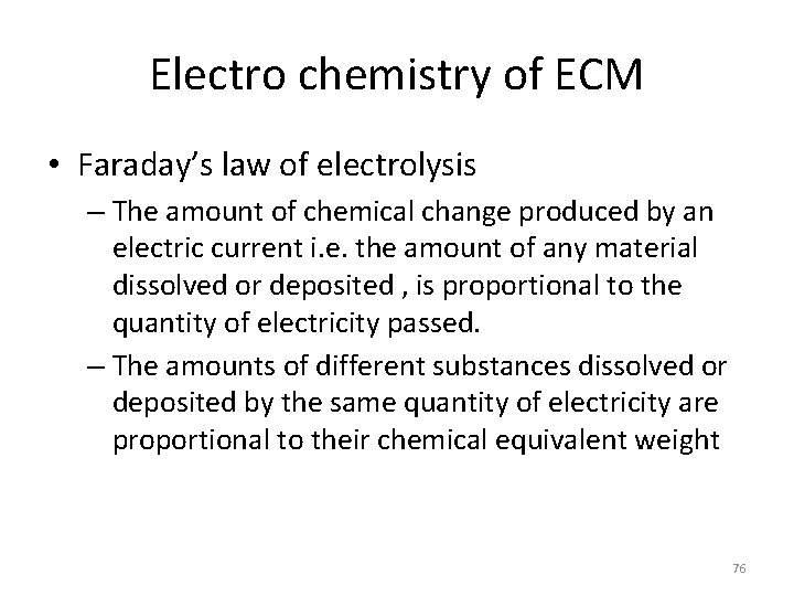
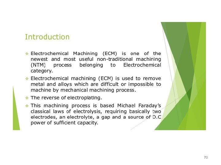
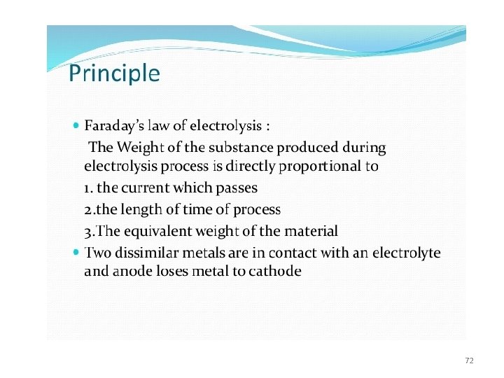
Electro chemistry of ECM • Faraday’s law of electrolysis – The amount of chemical change produced by an electric current i. e. the amount of any material dissolved or deposited , is proportional to the quantity of electricity passed. – The amounts of different substances dissolved or deposited by the same quantity of electricity are proportional to their chemical equivalent weight 76
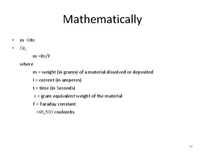
Mathematically • m →Itϵ • Or, m =Itϵ/F where m = weight (in grams) of a material dissolved or deposited I = current (in amperes) t = time (in Seconds) ϵ = gram equivalent weight of the material F = Faraday constant =96, 500 coulombs 77
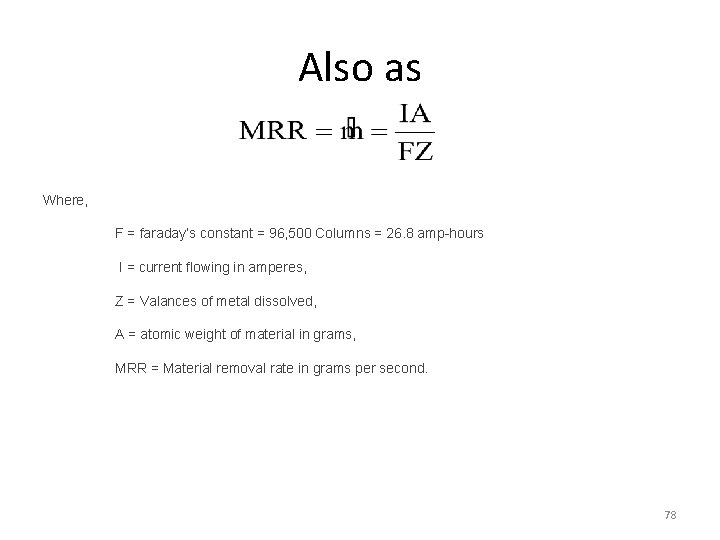
Also as Where, F = faraday’s constant = 96, 500 Columns = 26. 8 amp-hours I = current flowing in amperes, Z = Valances of metal dissolved, A = atomic weight of material in grams, MRR = Material removal rate in grams per second. 78
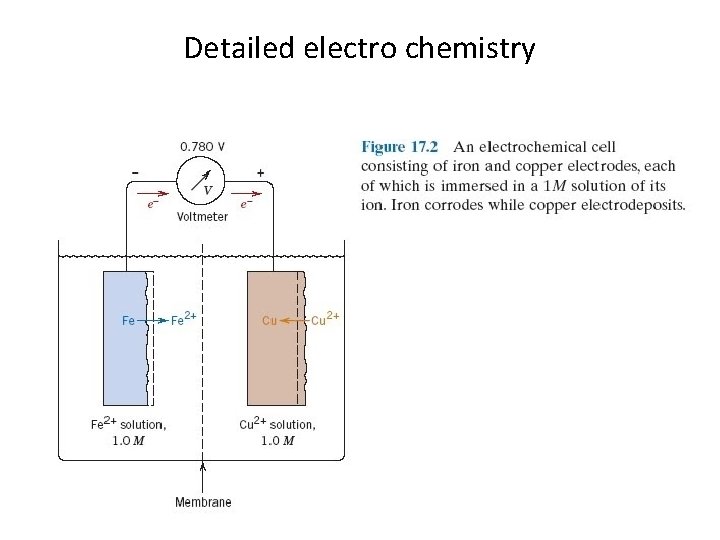
Detailed electro chemistry 79
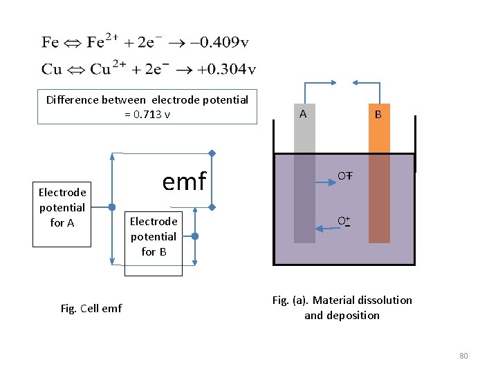
Difference between electrode potential = 0. 713 v Electrode potential for A Fig. Cell emf Electrode potential for B A B OŦ O+ Fig. (a). Material dissolution and deposition 80
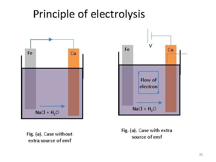
Principle of electrolysis Fe Cu Fe V Cu Flow of electron Na. Cl + H 2 O Fig. (a). Case without extra source of emf Na. Cl + H 2 O Fig. (a). Case with extra source of emf 81
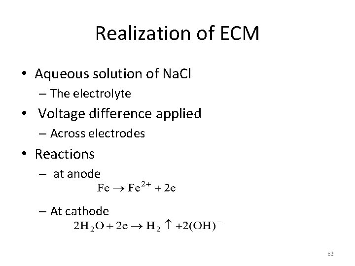
Realization of ECM • Aqueous solution of Na. Cl – The electrolyte • Voltage difference applied – Across electrodes • Reactions – at anode – At cathode 82
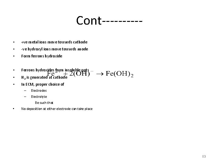
Cont----- • +ve metal ions move towards cathode • -ve hydroxyl ions move towards anode • Form ferrous hydroxide • Ferrous hydroxides form insoluble ppts • H 2 is generated at cathode • In ECM, proper choice of – Electrodes – Electrolyte Be such that • No deposition at either electrode can take place 83
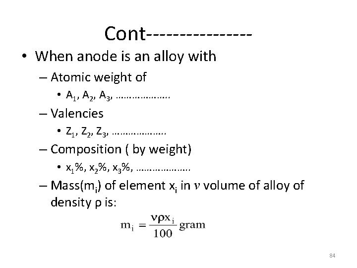
Cont-------- • When anode is an alloy with – Atomic weight of • A 1, A 2, A 3, ………………. . – Valencies • Z 1, Z 2, Z 3, ………………. . – Composition ( by weight) • x 1%, x 2%, x 3%, ………………. . – Mass(mi) of element xi in v volume of alloy of density ρ is: 84
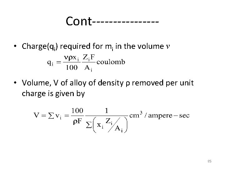
Cont-------- • Charge(qi) required for mi in the volume v • Volume, V of alloy of density ρ removed per unit charge is given by 85
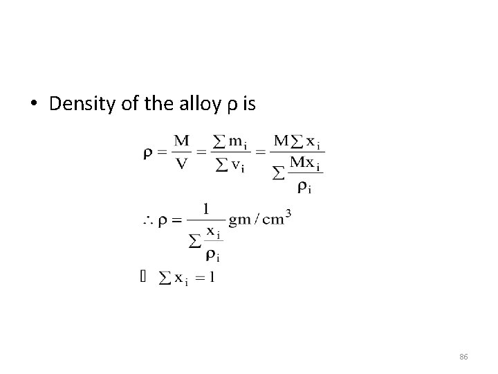
• Density of the alloy ρ is 86
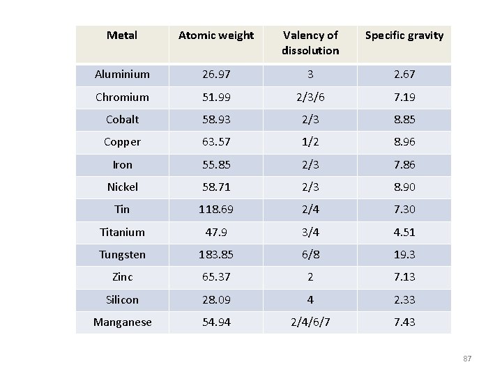
Metal Atomic weight Valency of dissolution Specific gravity Aluminium 26. 97 3 2. 67 Chromium 51. 99 2/3/6 7. 19 Cobalt 58. 93 2/3 8. 85 Copper 63. 57 1/2 8. 96 Iron 55. 85 2/3 7. 86 Nickel 58. 71 2/3 8. 90 Tin 118. 69 2/4 7. 30 Titanium 47. 9 3/4 4. 51 Tungsten 183. 85 6/8 19. 3 Zinc 65. 37 2 7. 13 Silicon 28. 09 4 2. 33 Manganese 54. 94 2/4/6/7 7. 43 87
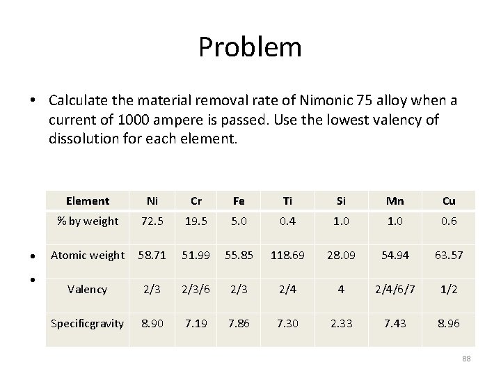
Problem • Calculate the material removal rate of Nimonic 75 alloy when a current of 1000 ampere is passed. Use the lowest valency of dissolution for each element. Element Ni Cr Fe Ti Si Mn Cu % by weight 72. 5 19. 5 5. 0 0. 4 1. 0 0. 6 118. 69 28. 09 54. 94 63. 57 2/4 4 2/4/6/7 1/2 7. 30 2. 33 7. 43 8. 96 3/min 51. 99 55. 85 Atomic weight 58. 71 • Answer: 2. 1 cm 3/min • Experimental value: 2. 0 cm Valency 2/3/6 2/3 Specificgravity 8. 90 7. 19 7. 86 88
In actual ECM process • Various factors affect mrr • Process is seldom ideal • Actual mrr differs from theoretical equation – Dissolution depends on work material • E. g. mrr with Ni as work material – Theoretically Ni is based as divalent – At higher current trivalent dissolution takes place – Sometimes dissolution valence depends on electrolytes • E. g. Copper – Mono-valent in chloride solutions – Divalent nitrite solutions 89
Potential profile across the electrode 1. Electrode potential 2. Over-voltage Due to activation polarization Electrochemical changes is in equilibrium when no current flows Electrode potential acts as barrier to a faster rate of reaction Additional energy to be supplied to get required mrr 90
Cont. . . 3. Concentration polarization Ions migrates towards the electrodes of opposite polarities Cause concentration of ions near the electrode surfaces Each ion passes through this concentration barrier to release its charge Extra voltage is required 4. Ohmic over-voltage o 5. Extra resistance to the passage of current due to thr solid films of solid materials formed on the electrolyte surface Ohmic resistance of electrolyte – Due to ohmic voltage drop across the bulk electrolyte – This is main voltage drop in the circuit which obey Ohm’s law 91
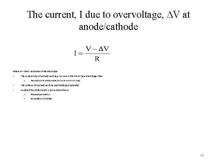
The current, I due to overvoltage, ∆V at anode/cathode Where R = ohmic resistance of the electrolyte • The conductivity of tool and work (e. g. For iron is 105 Ω-1 cm-1 )are much larger than – the conductivity of electrolyte (i. e. 0. 1 to 1. 0 Ω -1 cm-1 only). • The surfaces of tool and work are practically equi-potential. • Conductivity of electrolyte is not constant due to – Temperature variation – Accumulation of bubbles 92
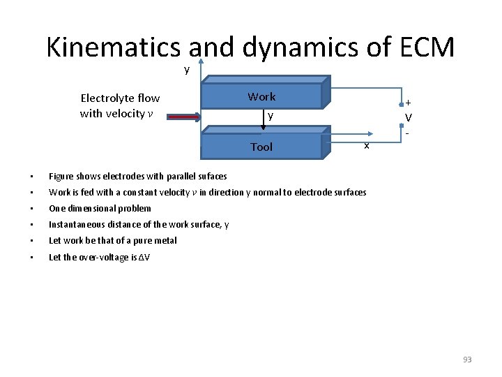
Kinematics and dynamics of ECM y Electrolyte flow with velocity v Work y Tool x • Figure shows electrodes with parallel sufaces • Work is fed with a constant velocity v in direction y normal to electrode surfaces • One dimensional problem • Instantaneous distance of the work surface, y • Let work be that of a pure metal • Let the over-voltage is ∆V + V - 93
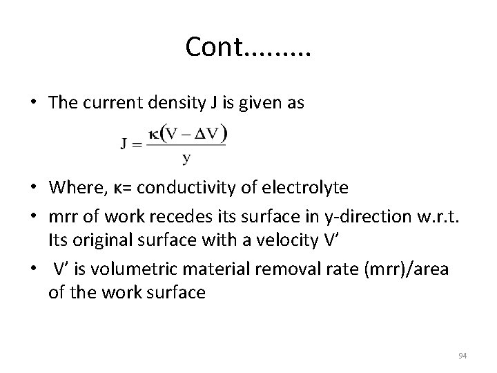
Cont. . • The current density J is given as • Where, κ= conductivity of electrolyte • mrr of work recedes its surface in y-direction w. r. t. Its original surface with a velocity V’ • V’ is volumetric material removal rate (mrr)/area of the work surface 94
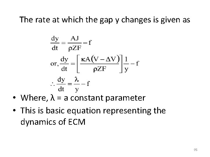
The rate at which the gap y changes is given as • Where, λ = a constant parameter • This is basic equation representing the dynamics of ECM 95
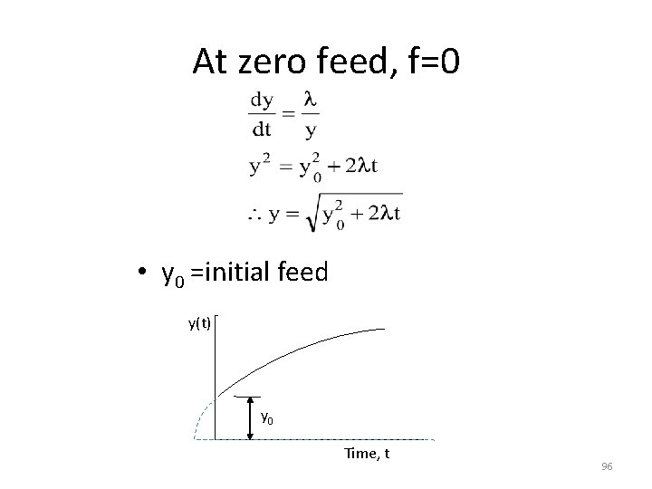
At zero feed, f=0 • y 0 =initial feed y(t) y 0 Time, t 96
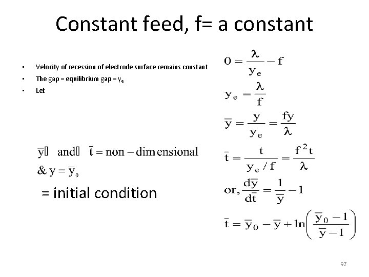
Constant feed, f= a constant • Velocity of recession of electrode surface remains constant • The gap = equilibrium gap = ye • Let = initial condition 97
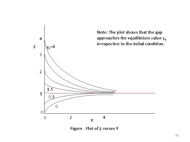
Note: The plot shows that the gap approaches the equilibrium value ye irrespective to the initial condition. 4 ȳ y 0=4 3 2 1 0 0 1. 5 0 2 Ŧ 4 Figure. Plot of ȳ verses Ŧ 98
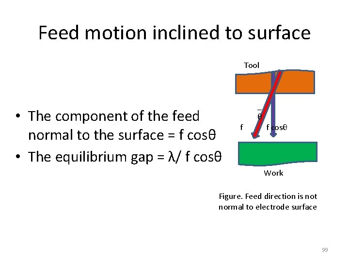
Feed motion inclined to surface Tool • The component of the feed normal to the surface = f cosθ • The equilibrium gap = λ/ f cosθ _ θ f f cosθ Work Figure. Feed direction is not normal to electrode surface 99
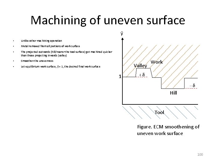
Machining of uneven surface ȳ • Unlike other machining operation • Metal removed from all portions of work surface • The projected outwards (hill/nearer the tool surface) get machined quicker than those projecting inwards (valley) • Smoothen the unevenness • Let equilibrium work surface, ȳ = 1, the desired final work surface Valley Work 1 Hill Tool Figure. ECM smoothening of uneven work surface 100
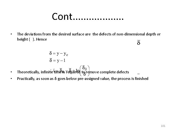
Cont. . . . . • The deviations from the desired surface are the defects of non-dimensional depth or height ( ). Hence • Theoretically, infinite time is required to remove complete defects _ • Practically, as soon as δ goes below pre-assigned value, the process is finished 101
Problem • In an ECM process on a flat surface, a 10 V dc supply is used. the conductivity of electrolyte is 0. 2 Ω -1 cm-1, and feed rate is 1 mm/min. The work-piece is pure cobalt. Calculate the equilibrium gap when the over-voltage is 1. 5 V. (At. wt. = 58. 93, Z = 2, ρ = 8. 85). Ans. 0. 04 cm • If work material is pure iron then, ye = 0. 04 cm. • Theoretically, ye can be of any value. But – in practice, the tool surface is not perfectly flat – If ye is too small, tool may touch the work and cause short circuit 102
Problem • The surface irregularities of tool and work are 5 μm and 8 μm respectively. The work is of pure nickel and a dc of 12 V is employed. estimate the largest feed rate. assume an over-voltage of 1. 5 V. (At. wt. = 58. 71, Z = 2, ρ = 8. 90). • Ans. 35. 7 mm/min 103
Machining force • Material removal takes place at the atomic level. • It appears to be negligible, but • Electrolyte is to be provided adequately • Large hydro-static force on – tool – work • Electrolyte flow – avoids ion concentration – avoids deposition on tool – removes precipitates – avoids over heating • it is very important parameter 104
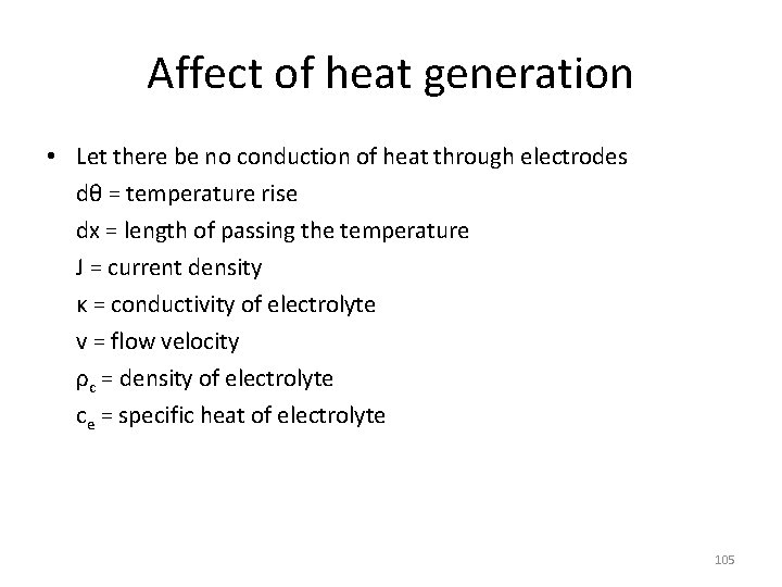
Affect of heat generation • Let there be no conduction of heat through electrodes dθ = temperature rise dx = length of passing the temperature J = current density κ = conductivity of electrolyte v = flow velocity ρc = density of electrolyte ce = specific heat of electrolyte 105
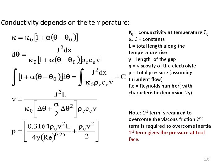
Conductivity depends on the temperature: K 0 = conductivity at temperature θ 0 α, C = constants L = total length along the temperature rise y = length of the gap η = viscosity of the electrolyte p = total pressure (assuming turbulent flow) Re = Reynolds number( with characteristic dimension 2 y) Note: 1 st term is required to overcome the viscous friction 2 nd term is required to overcome inertia 1 st term gives the pressure at tool face. 106
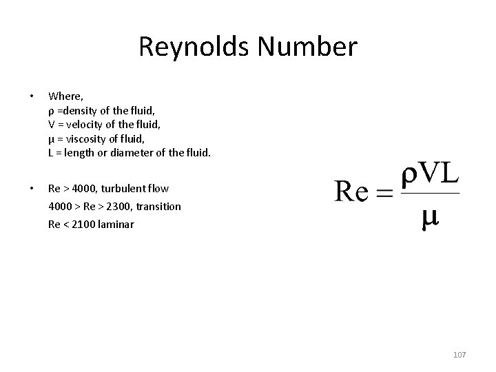
Reynolds Number • Where, ρ =density of the fluid, V = velocity of the fluid, μ = viscosity of fluid, L = length or diameter of the fluid. • Re > 4000, turbulent flow 4000 > Re > 2300, transition Re < 2100 laminar 107
Problem • During ECM on iron work with a square face (25. 4 mm x 25. 4 mm) copper tool, brine electrolyte is used at a feed rate of 2 mm/min. Both (tool and work) have flat surfaces. The dc voltage used is 10 V and total over-voltage is 1. 5 V. Boiling temperature of electrolyte is 95 o. C. Compute the force acting on the tool. Assume the following properties of the electrolyte: Viscosity = 0. 876 x 10 -3 kg/m-sec Relative density = 1. 088 Specific heat = o. 997 Conductivity = 0. 2 Ω-1 cm-1 Ambient temperature = 35 o. C Neglect the variation in conductivity of electrolyte due to the temperature change. The electrolyte is fed from one side of the square shaped tool. Ans. 238 k. N/m 2, 79 N 108
Effect of heat and H 2 bubbles generation • Change in conductivity of electrolyte due to – Increase in electrolyte temperature • Flow of electricity • Change in conductivity • Non-uniformity in current density along the direction of electrolyte flow – Evolution of hydrogen bubbles • During machining • Swept by electrolyte • Increase in concentration of bubbles in the direction of electrolyte flow • Overall increase in current density in the direction of electrolyte flow • Causes variation in equilibrium gap – Formation of precipitates 109
Surface finish • Surface finish is adversely affected by – Selective dissolution – Sporadic breakdown of the anodic film – Flow separation and formation of eddies – Evolution of hydrogen gas 110
Selective dissolution • In alloys – Different constituents – with varying electrode potentials • In pure metals – Dissolution potentials at grain boundaries are different from – Those inside the grain 111
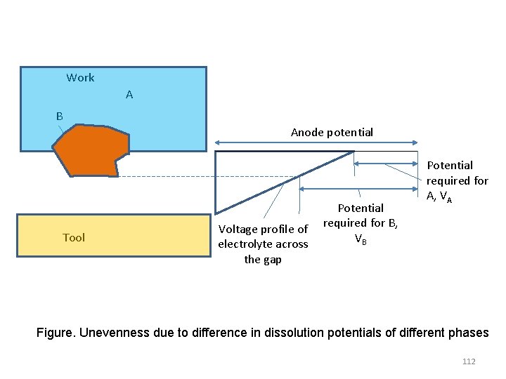
Work A B Anode potential Tool Potential Voltage profile of required for B, VB electrolyte across the gap Potential required for A, VA Figure. Unevenness due to difference in dissolution potentials of different phases 112
• • • Let two constituents are A & B with Dissolution potentials of VB > VA Since whole anode surface is equi-potential And electrolyte potential varies across the gap Surface of grain B projects away from the constituent A – To meet the electrolyte with a lower potential – So that a larger difference VB is achieved • At steady state the work surface will be uneven 113
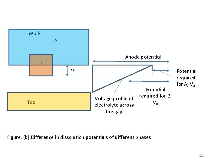
Work A Anode potential B δ Tool Potential Voltage profile of required for B, VB electrolyte across the gap Potential required for A, VA Figure. (b) Difference in dissolution potentials of different phases 114
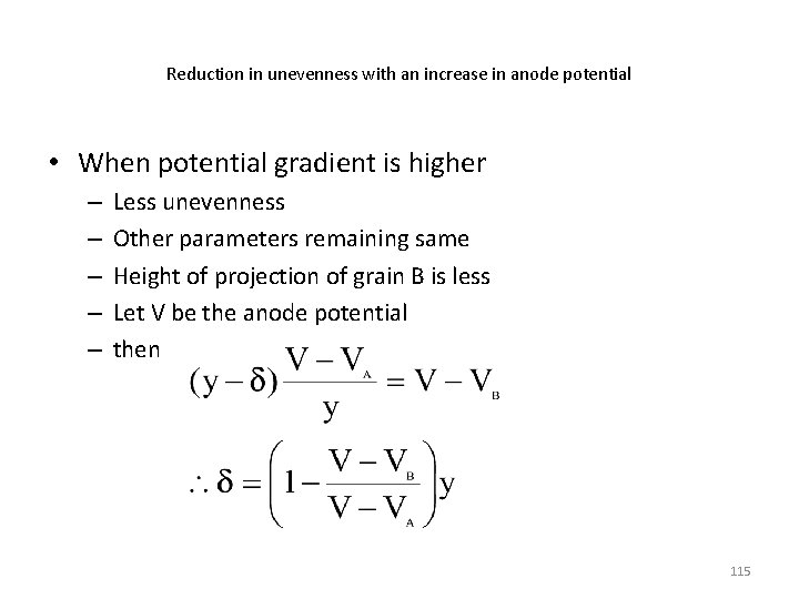
Reduction in unevenness with an increase in anode potential • When potential gradient is higher – – – Less unevenness Other parameters remaining same Height of projection of grain B is less Let V be the anode potential then 115
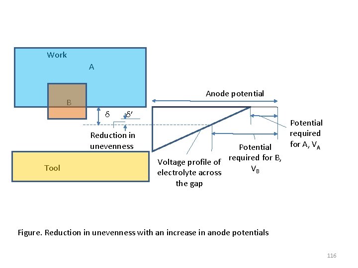
Work A Anode potential B δ δ’ Reduction in unevenness Tool Potential Voltage profile of required for B, VB electrolyte across the gap Potential required for A, VA Figure. Reduction in unevenness with an increase in anode potentials 116
Sporadic breakdown of anodic film • Main reason – Gradual fall in potential difference between • the work surface and • the electrolyte region – away from the machining area 117
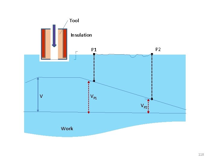
Tool Insulation P 2 P 1 V VP 1 VP 2 Work 118
Sporadic breakdown of anodic film (cont. . ) • Till P 1 – • The potential is enough to cause dissolution At P 1 – Potential falls below dissolution potential of one phase • – Continues to fall • • Stops dissolution of more phases – Results uneven surface – Ultimately only a few phases dissolve – Active phases occupy part of anode surface – Results concentration of electric field – These phases dissolve rapidly – Form pits Beyond P 2 – Anode surface potential drops very low – No dissolution 119
Flow separation and formation of eddies • Hills and valleys on anode surface – May be due to • Improper tool design • Electrolyte flow path – – – – Separation of electrolyte flow Formation of eddy Separated from main stream A large concentration of metal ions Results in high concentration over-voltage Location variation of material removal rates Uneven surface finish 120
Evolution of hydrogen gas • Collected by the flowing electrolyte • Reduces specific conductivity of electrolyte • Increases hydrogen concentration in downstream • Overall deteriorates surface finish 121
Tool design Major aspects of tool design: • Determination of tool shape • Considerations e. g. – Electrolyte flow – Insulation – Strength – Etc. 122
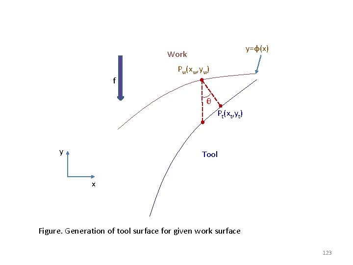
y=φ(x) Work f Pw(xw, yw) θ Pt(xt, yt) y Tool x Figure. Generation of tool surface for given work surface 123
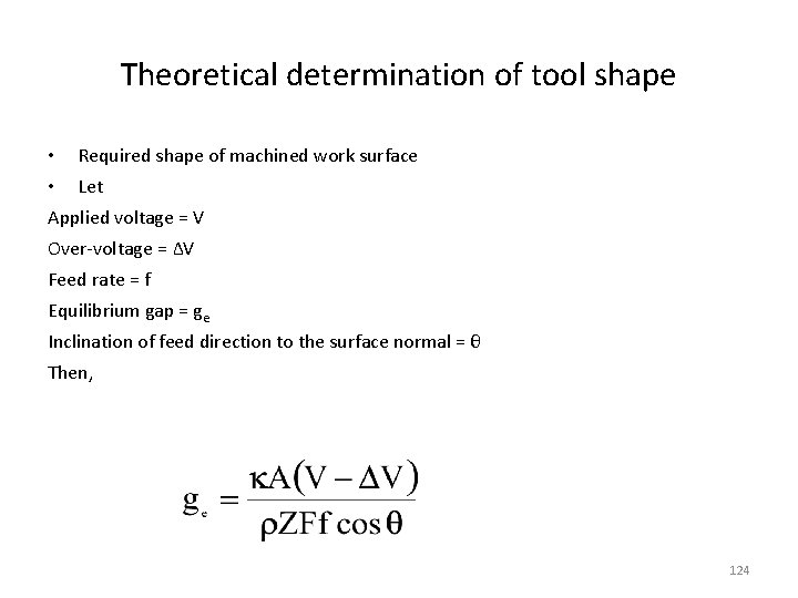
Theoretical determination of tool shape • Required shape of machined work surface • Let Applied voltage = V Over-voltage = ∆V Feed rate = f Equilibrium gap = ge Inclination of feed direction to the surface normal = θ Then, 124
Cont. . • Coordinates x and y are so that y-axis and feed direction are parallel • Let there be no variation in z-direction • Hence, work tool geometry be y = φ(x) • At steady state, any point Pw(xw, yw) on work can be transform into Pt(xt, yt) on tool surface • So that Pw. Pt = ge 125
Cont. . • Then 126
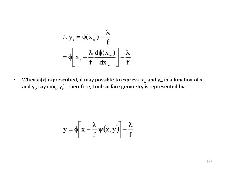
• When φ(x) is prescribed, it may possible to express xw and yw in a function of xt and yt, say ψ(xt, yt). Therefore, tool surface geometry is represented by: 127

Cont. . 128
In case of 3 -dimensions • E. g. y = a + bx + cx 2 + dz + ez 2 + gxz • Required geometry can be computed Note: The method discussed above is applicable for smooth surfaces with gentle variation i. e. the current flow line are or parallel to one another. • For complex shapes • sharp curves • sudden changes – Solution of electric field is necessary 129
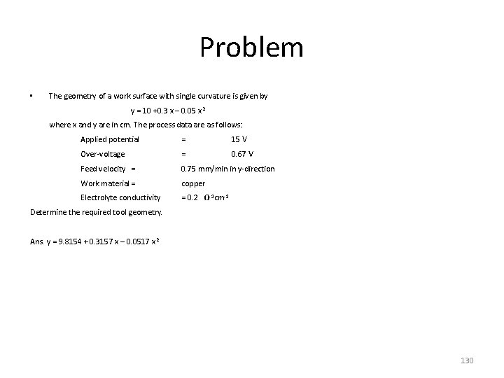
Problem • The geometry of a work surface with single curvature is given by y = 10 +0. 3 x – 0. 05 x 2 where x and y are in cm. The process data are as follows: Applied potential = 15 V Over-voltage = 0. 67 V Feed velocity = 0. 75 mm/min in y-direction Work material = copper Electrolyte conductivity = 0. 2 Ω-1 cm-1 Determine the required tool geometry. Ans. y = 9. 8154 + 0. 3157 x – 0. 0517 x 2 130
Further design considerations • Design for electrolyte flow • Design for insulation • etc 131
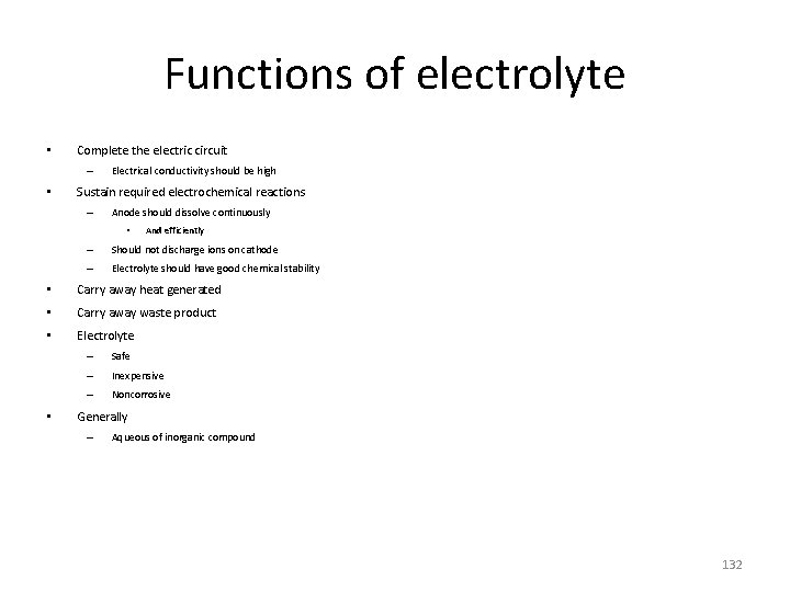
Functions of electrolyte • Complete the electric circuit – • Electrical conductivity should be high Sustain required electrochemical reactions – Anode should dissolve continuously • And efficiently – Should not discharge ions on cathode – Electrolyte should have good chemical stability • Carry away heat generated • Carry away waste product • Electrolyte • – Safe – Inexpensive – Noncorrosive Generally – Aqueous of inorganic compound 132
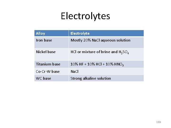
Electrolytes Alloy Electrolyte Iron base Mostly 20% Na. Cl aqueous solution Nickel base HCl or mixture of brine and H 2 SO 4 Titanium base 10% HF + 10% HCl + 10% HNO 3 Co-Cr-W base Na. Cl WC base Strong alkaline solution 133
134
Effects of electrolyte • Material removal is gentle • Low (~zero) residual compressive stress – ~ 50 kg/mm 2 conventional machining processes – 10 to 25% lower fatigue strength of product • – • Because of – Micro crack surface are exposed – Stress free surface Fatigue strength can be increased • Mechanical polishing • Glass bead blasting • Vapour blasting etc Negligible depth (0. 001 mm) of work hardened surface – While 0. 5 mm to 1. 5 mm in conventional machining processes 135

Thanks 136
- Slides: 136