
Advanced Gravitationalwave Detector Technologies Future generations of interferometers
- Slides: 41
Advanced Gravitational-wave Detector Technologies Future generations of interferometers Nergis Mavalvala LIGO Scientific Collaboration GR-17, July 2004
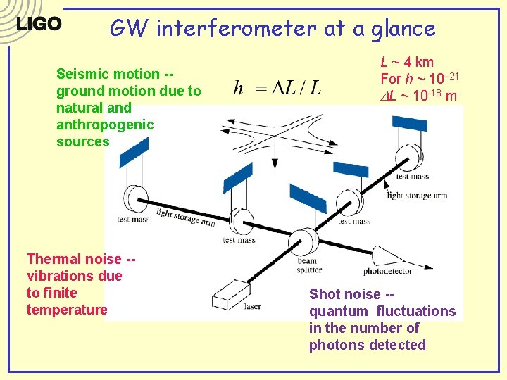
GW interferometer at a glance Seismic motion -ground motion due to natural and anthropogenic sources Thermal noise -vibrations due to finite temperature L ~ 4 km For h ~ 10– 21 DL ~ 10 -18 m Shot noise -quantum fluctuations in the number of photons detected
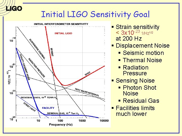
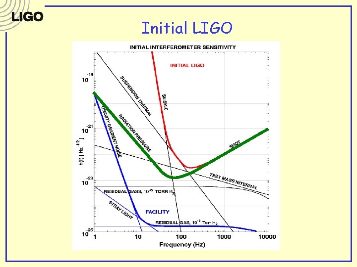
Initial LIGO Sensitivity Goal § Strain sensitivity < 3 x 10 -23 1/Hz 1/2 at 200 Hz § Displacement Noise § Seismic motion § Thermal Noise § Radiation Pressure § Sensing Noise § Photon Shot Noise § Residual Gas § Facilities limits much lower
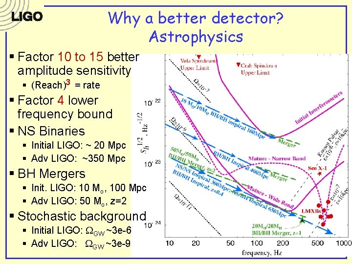
Why a better detector? Astrophysics § Factor 10 to 15 better amplitude sensitivity § (Reach)3 = rate § Factor 4 lower frequency bound § NS Binaries § Initial LIGO: ~ 20 Mpc § Adv LIGO: ~350 Mpc § BH Mergers § Init. LIGO: 10 Mo, 100 Mpc § Adv LIGO: 50 Mo, z=2 § Stochastic background § Initial LIGO: WGW ~3 e-6 § Adv LIGO: WGW ~3 e-9
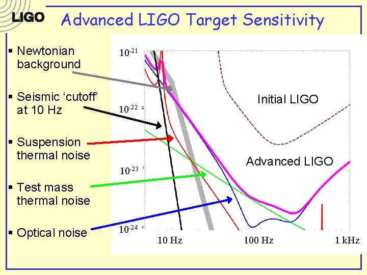
Advanced LIGO Target Sensitivity § Newtonian background § Seismic ‘cutoff’ at 10 Hz 10 -21 Initial LIGO 10 -22 § Suspension thermal noise Advanced LIGO 10 -23 § Test mass thermal noise § Optical noise 10 -24 10 Hz 100 Hz 1 k. Hz
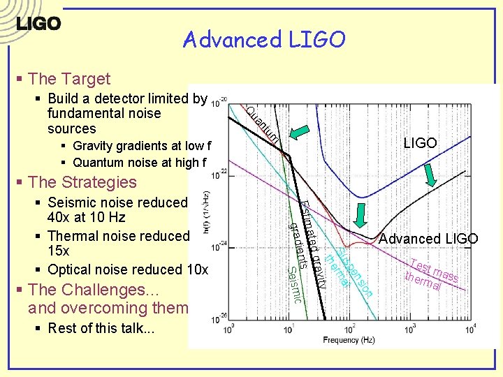
Advanced LIGO § The Target nt ua um § Gravity gradients at low f § Quantum noise at high f Q § Build a detector limited by fundamental noise sources LIGO § The Strategies § Rest of this talk. . . n sio en sp l Su rma the § The Challenges. . . and overcoming them ravity ated g Estim nts e ic gradi Seism § Seismic noise reduced 40 x at 10 Hz § Thermal noise reduced 15 x § Optical noise reduced 10 x Advanced LIGO Tes t ther mass mal
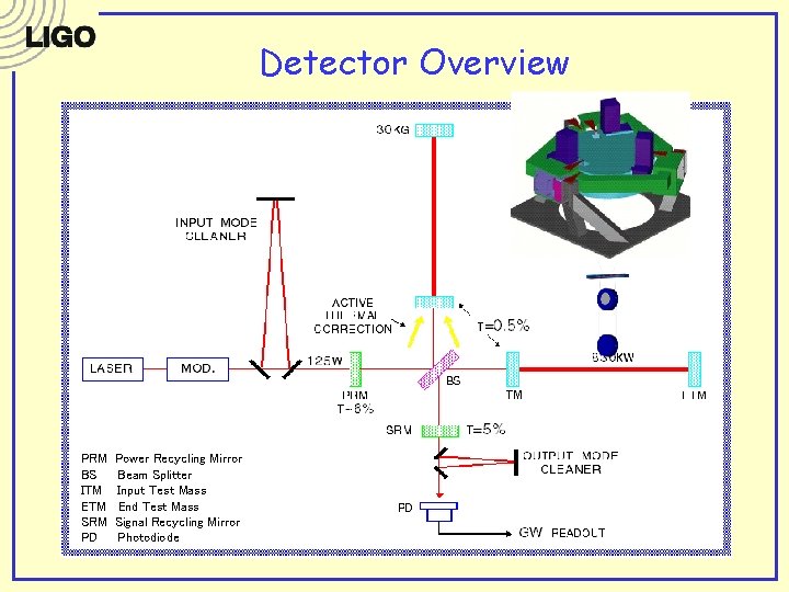
Detector Overview PRM BS ITM ETM SRM PD Power Recycling Mirror Beam Splitter Input Test Mass End Test Mass Signal Recycling Mirror Photodiode
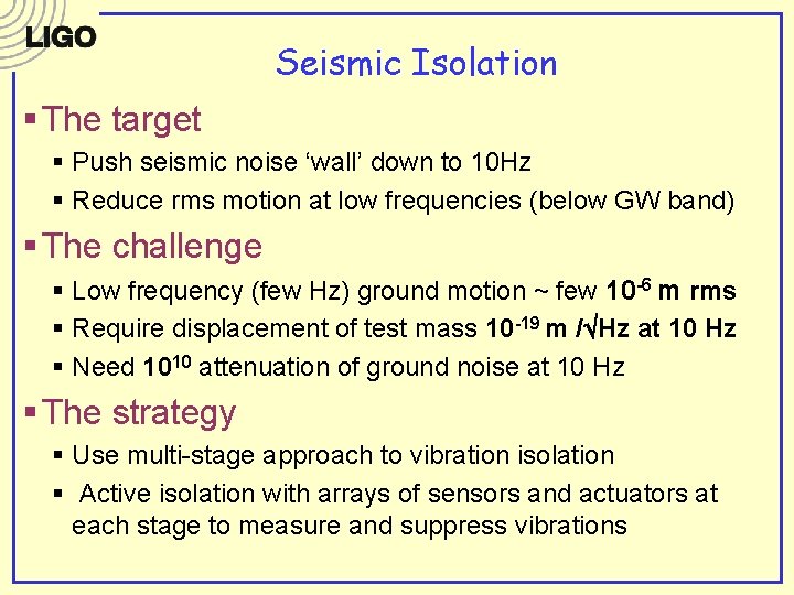
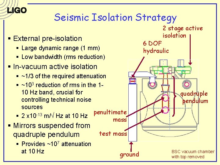
Seismic Isolation § The target § Push seismic noise ‘wall’ down to 10 Hz § Reduce rms motion at low frequencies (below GW band) § The challenge § Low frequency (few Hz) ground motion ~ few 10 -6 m rms § Require displacement of test mass 10 -19 m / Hz at 10 Hz § Need 1010 attenuation of ground noise at 10 Hz § The strategy § Use multi-stage approach to vibration isolation § Active isolation with arrays of sensors and actuators at each stage to measure and suppress vibrations
Seismic Isolation Strategy 2 stage active isolation § External pre-isolation 6 DOF hydraulic § Large dynamic range (1 mm) § Low bandwidth (rms reduction) § In-vacuum active isolation § ~1/3 of the required attenuation § ~103 reduction of rms in the 110 Hz band, crucial for controlling technical noise sources penultimate § 2 x 10 -13 m/ Hz at 10 Hz mass § Mirrors suspended from quadruple pendulum § Provides ~107 attenuation at 10 Hz quadruple pendulum test mass ground BSC vacuum chamber with top removed
Optics suspensions and controls § The requirements § Provide additional isolation § Keep suspension thermal noise to a minimum (avoid mechanical dissipation points) § Damp free motions § Provide means for controlling longitudinal and angular positions of mirrors without adding control noise § The strategy § Suspension design to minimize thermal noise § Magnets and coils for position/pointing control § Filter control noise
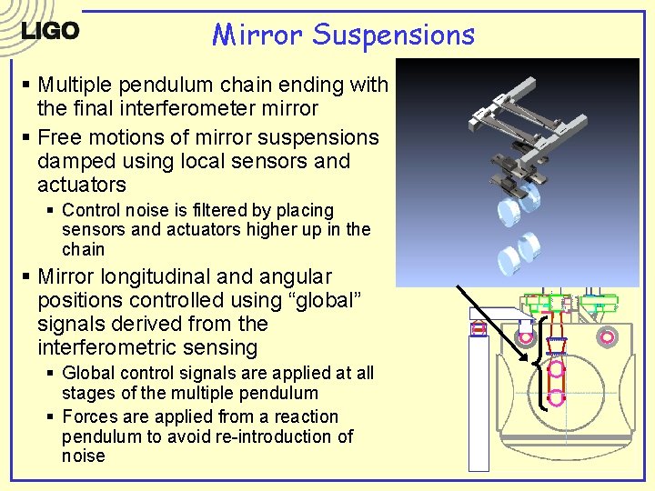
Mirror Suspensions § Multiple pendulum chain ending with the final interferometer mirror § Free motions of mirror suspensions damped using local sensors and actuators § Control noise is filtered by placing sensors and actuators higher up in the chain § Mirror longitudinal and angular positions controlled using “global” signals derived from the interferometric sensing § Global control signals are applied at all stages of the multiple pendulum § Forces are applied from a reaction pendulum to avoid re-introduction of noise
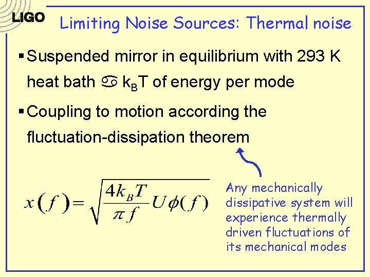
Limiting Noise Sources: Thermal noise § Suspended mirror in equilibrium with 293 K heat bath a k. BT of energy per mode § Coupling to motion according the fluctuation-dissipation theorem Any mechanically dissipative system will experience thermally driven fluctuations of its mechanical modes
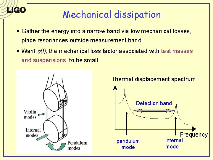
Mechanical dissipation § Gather the energy into a narrow band via low mechanical losses, place resonances outside measurement band § Want f(f), the mechanical loss factor associated with test masses and suspensions, to be small Thermal displacement spectrum Detection band Frequency pendulum mode internal mode
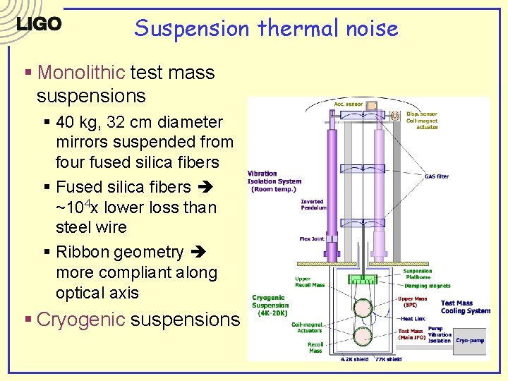
Suspension thermal noise § Monolithic test mass suspensions § 40 kg, 32 cm diameter mirrors suspended from four fused silica fibers § Fused silica fibers ~104 x lower loss than steel wire § Ribbon geometry more compliant along optical axis § Cryogenic suspensions
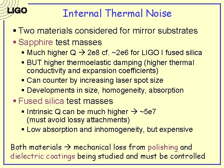
Internal Thermal Noise § Two materials considered for mirror substrates § Sapphire test masses § Much higher Q 2 e 8 cf. ~2 e 6 for LIGO I fused silica § BUT higher thermoelastic damping (higher thermal conductivity and expansion coefficients) § Can counter by increasing laser spot size § Developments in size, homogeneity, absorption § Fused silica test masses § Intrinsic Q can be much higher ~5 e 7 (must avoid lossy attachments) § Low absorption and inhomogeneity, but expensive Both materials mechanical loss from polishing and dielectric coatings being studied and must be controlled
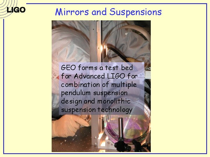
Mirrors and Suspensions GEO forms a test bed for Advanced LIGO for combination of multiple pendulum suspension design and monolithic 30 cm suspension technology
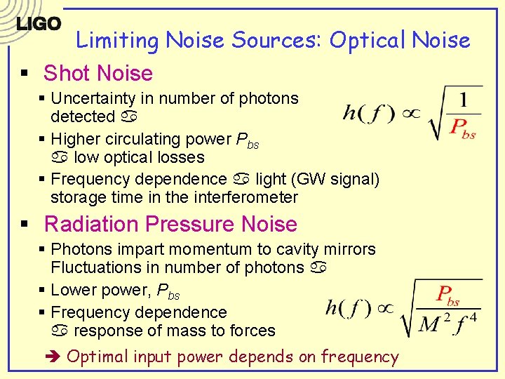
Limiting Noise Sources: Optical Noise § Shot Noise § Uncertainty in number of photons detected a § Higher circulating power Pbs a low optical losses § Frequency dependence a light (GW signal) storage time in the interferometer § Radiation Pressure Noise § Photons impart momentum to cavity mirrors Fluctuations in number of photons a § Lower power, Pbs § Frequency dependence a response of mass to forces Optimal input power depends on frequency
Initial LIGO
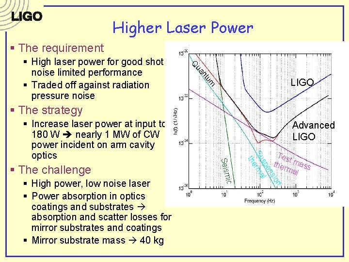
Higher Laser Power § The requirement nt ua Q LIGO um § High laser power for good shot noise limited performance § Traded off against radiation pressure noise § The strategy ic § High power, low noise laser § Power absorption in optics coatings and substrates absorption and scatter losses for mirror substrates and coatings § Mirror substrate mass 40 kg Tes t ther mass mal n sio en sp l Su rma the § The challenge Advanced LIGO Seism § Increase laser power at input to 180 W nearly 1 MW of CW power incident on arm cavity optics
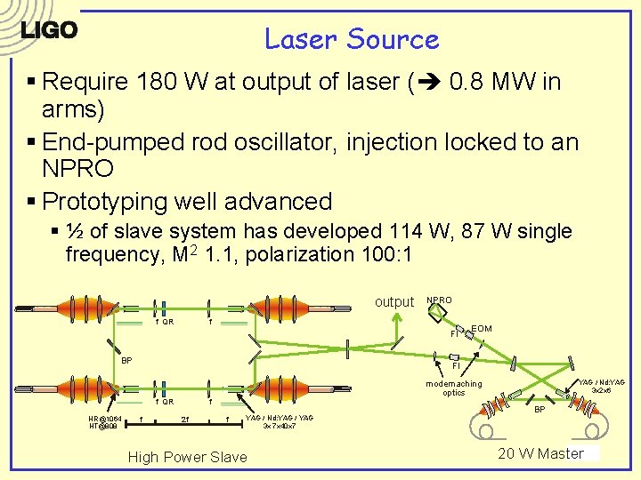
Laser Source § Require 180 W at output of laser ( 0. 8 MW in arms) § End-pumped rod oscillator, injection locked to an NPRO § Prototyping well advanced § ½ of slave system has developed 114 W, 87 W single frequency, M 2 1. 1, polarization 100: 1 output f QR NPRO f FI BP FI f QR HR@1064 HT@808 EOM f modemaching optics f 2 f f YAG / Nd: YAG / YAG 3 x 7 x 40 x 7 High Power Slave YAG / Nd: YAG 3 x 2 x 6 BP 20 W Master
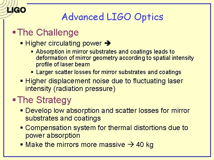
Advanced LIGO Optics § The Challenge § Higher circulating power § Absorption in mirror substrates and coatings leads to deformation of mirror geometry according to spatial intensity profile of laser beam § Larger scatter losses for mirror substrates and coatings § Higher displacement noise due to fluctuating laser intensity (radiation pressure) § The Strategy § Develop low absorption and scatter losses for mirror substrates and coatings § Compensation system for thermal distortions due to power absorption § Make the mirrors more massive 40 kg
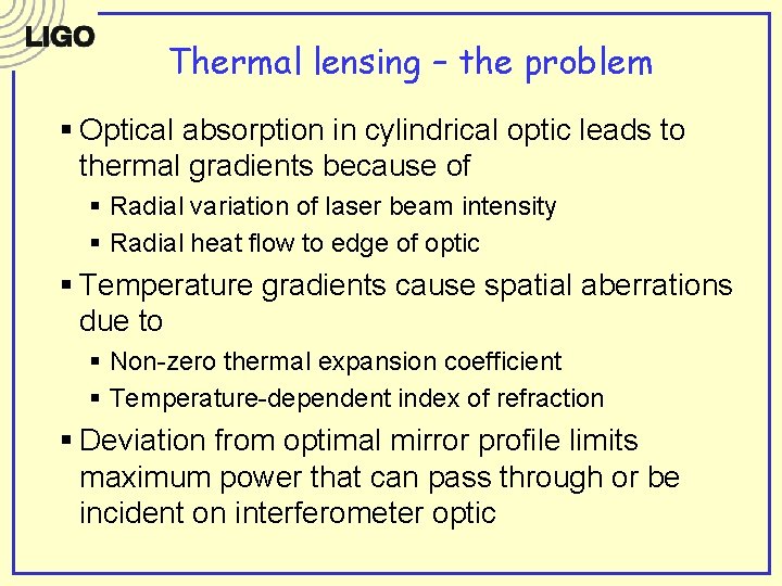
Thermal lensing – the problem § Optical absorption in cylindrical optic leads to thermal gradients because of § Radial variation of laser beam intensity § Radial heat flow to edge of optic § Temperature gradients cause spatial aberrations due to § Non-zero thermal expansion coefficient § Temperature-dependent index of refraction § Deviation from optimal mirror profile limits maximum power that can pass through or be incident on interferometer optic
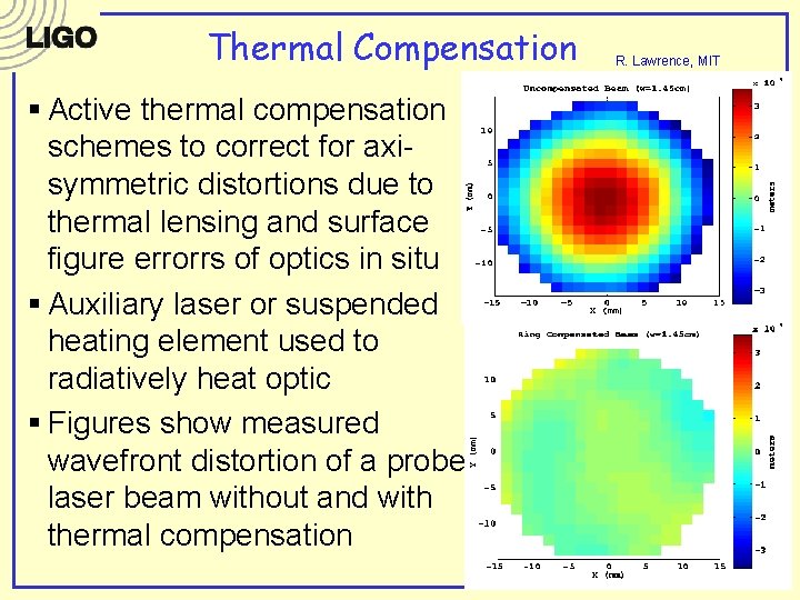
Thermal Compensation § Active thermal compensation schemes to correct for axisymmetric distortions due to thermal lensing and surface figure errorrs of optics in situ § Auxiliary laser or suspended heating element used to radiatively heat optic § Figures show measured wavefront distortion of a probe laser beam without and with thermal compensation R. Lawrence, MIT
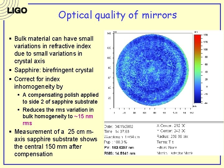
Optical quality of mirrors § Bulk material can have small variations in refractive index due to small variations in crystal axis § Sapphire: birefringent crystal § Correct for index inhomogeneity by § A compensating polish applied to side 2 of sapphire substrate § Reduces the rms variation in bulk homogeneity to ~15 nm rms § Measurement of a 25 cm maxis sapphire substrate shows the central 150 mm after compensation
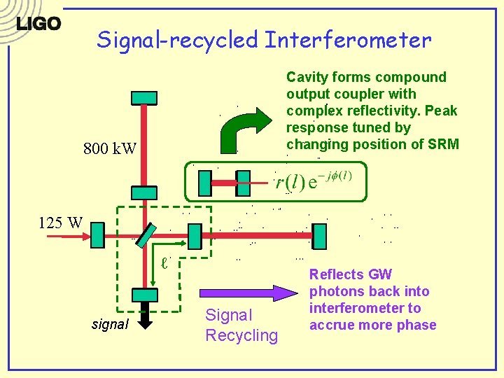
Signal-recycled Interferometer Cavity forms compound output coupler with complex reflectivity. Peak response tuned by changing position of SRM 800 k. W 125 W ℓ signal Signal Recycling Reflects GW photons back into interferometer to accrue more phase
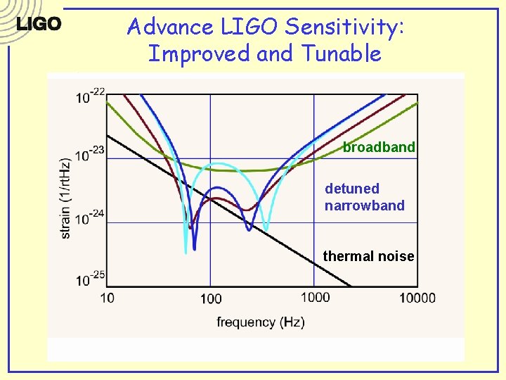
Advance LIGO Sensitivity: Improved and Tunable broadband detuned narrowband thermal noise
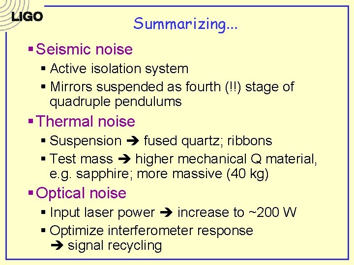
Summarizing. . . § Seismic noise § Active isolation system § Mirrors suspended as fourth (!!) stage of quadruple pendulums § Thermal noise § Suspension fused quartz; ribbons § Test mass higher mechanical Q material, e. g. sapphire; more massive (40 kg) § Optical noise § Input laser power increase to ~200 W § Optimize interferometer response signal recycling
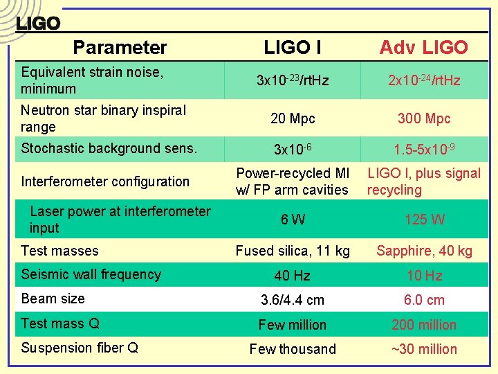
Parameter LIGO I Adv LIGO 3 x 10 -23/rt. Hz 2 x 10 -24/rt. Hz Neutron star binary inspiral range 20 Mpc 300 Mpc Stochastic background sens. 3 x 10 -6 1. 5 -5 x 10 -9 Interferometer configuration Power-recycled MI w/ FP arm cavities LIGO I, plus signal recycling 6 W 125 W Fused silica, 11 kg Sapphire, 40 kg 40 Hz 10 Hz Beam size 3. 6/4. 4 cm 6. 0 cm Test mass Q Few million 200 million Few thousand ~30 million Equivalent strain noise, minimum Laser power at interferometer input Test masses Seismic wall frequency Suspension fiber Q
Sub-Quantum Interferometers Generation 2++
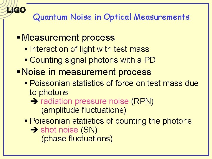
Quantum Noise in Optical Measurements § Measurement process § Interaction of light with test mass § Counting signal photons with a PD § Noise in measurement process § Poissonian statistics of force on test mass due to photons radiation pressure noise (RPN) (amplitude fluctuations) § Poissonian statistics of counting the photons shot noise (SN) (phase fluctuations)
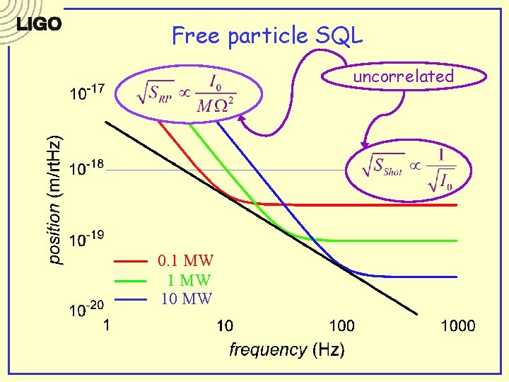
Free particle SQL uncorrelated 0. 1 MW 10 MW
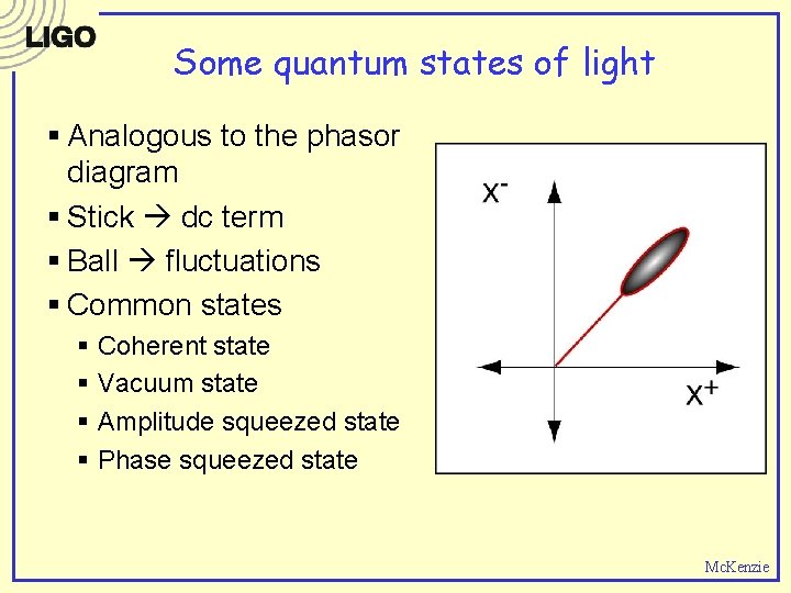
Some quantum states of light § Analogous to the phasor diagram § Stick dc term § Ball fluctuations § Common states § § Coherent state Vacuum state Amplitude squeezed state Phase squeezed state Mc. Kenzie
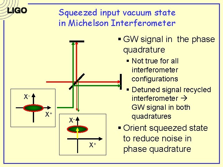
Squeezed input vacuum state in Michelson Interferometer § GW signal in the phase quadrature § Not true for all interferometer configurations § Detuned signal recycled interferometer GW signal in both quadratures -XX ++ XX XX- + X § Orient squeezed state to reduce noise in phase quadrature
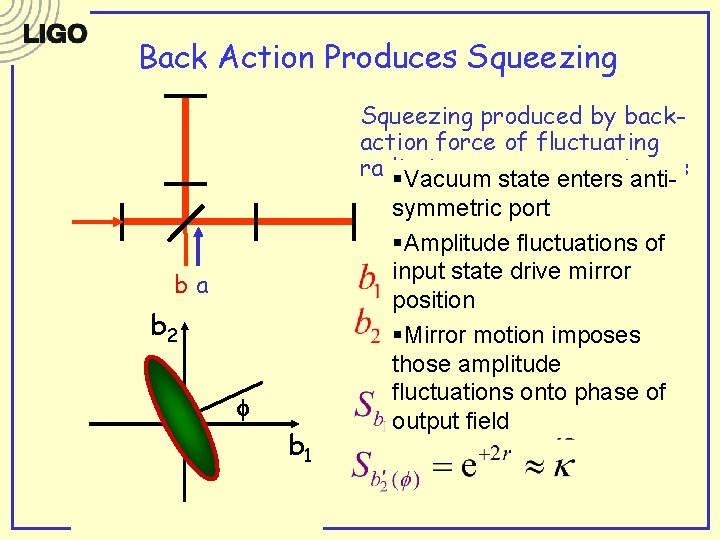
Back Action Produces Squeezing produced by backaction force of fluctuating radiation pressure on mirrors §Vacuum state enters anti- ba ba 22 f ba 11 symmetric port §Amplitude fluctuations of input state drive mirror position §Mirror motion imposes those amplitude fluctuations onto phase of output field
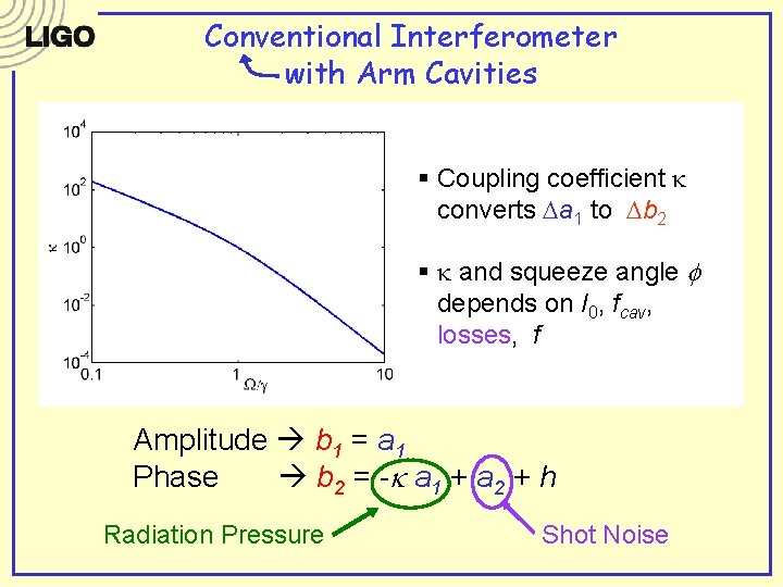
Conventional Interferometer with Arm Cavities § Coupling coefficient k converts Da 1 to Db 2 a b § k and squeeze angle f depends on I 0, fcav, losses, f Amplitude b 1 = a 1 Phase b 2 = - k a 1 + a 2 + h Radiation Pressure Shot Noise
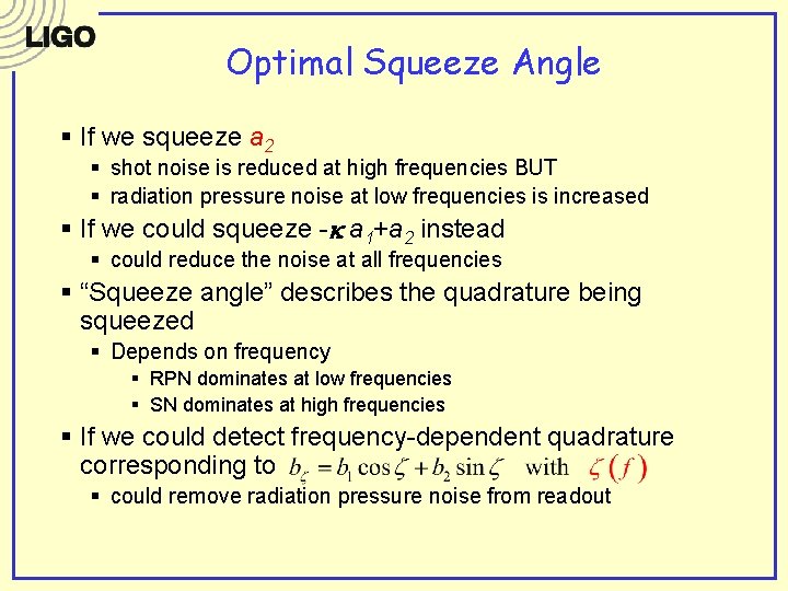
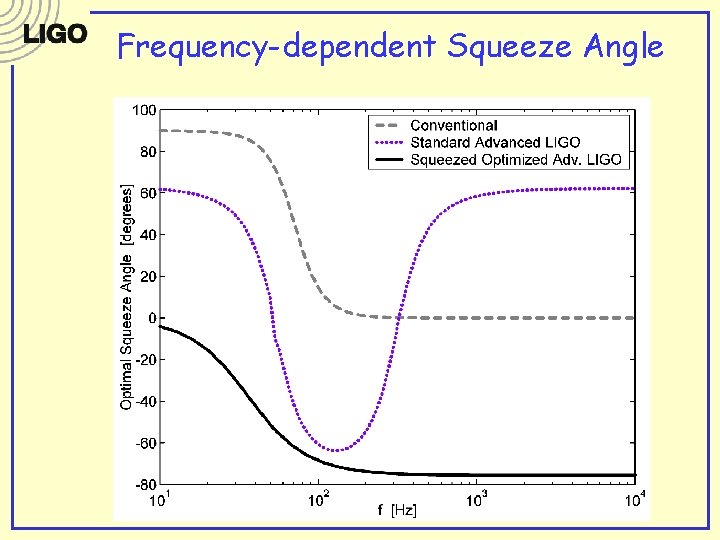
Optimal Squeeze Angle § If we squeeze a 2 § shot noise is reduced at high frequencies BUT § radiation pressure noise at low frequencies is increased § If we could squeeze -k a 1+a 2 instead § could reduce the noise at all frequencies § “Squeeze angle” describes the quadrature being squeezed § Depends on frequency § RPN dominates at low frequencies § SN dominates at high frequencies § If we could detect frequency-dependent quadrature corresponding to § could remove radiation pressure noise from readout
Frequency-dependent Squeeze Angle
Squeezing – the ubiquitous fix? § All interferometer configurations can benefit from squeezing § Radiation pressure noise can be removed from readout in certain cases § Shot noise limit only improved by more power (yikes!) or squeezing (eek!) § Reduction in shot noise by squeezing can allow for reduction in circulating power (for the same sensitivity)
Squeezed vacuum § Requirements § Squeezing at low frequencies (within GW band) § Frequency-dependent squeeze angle § Increased levels of squeezing § Generation methods § Non-linear optical media (c(2) and c(3) non-linearites) crystal-based squeezing (see ANU poster) § Radiation pressure effects in interferometers ponderomotive squeezing (in design & planning stages) § Challenges § Frequency-dependence filter cavities § Amplitude filters § Squeeze angle rotation filters § Low-loss optical systems
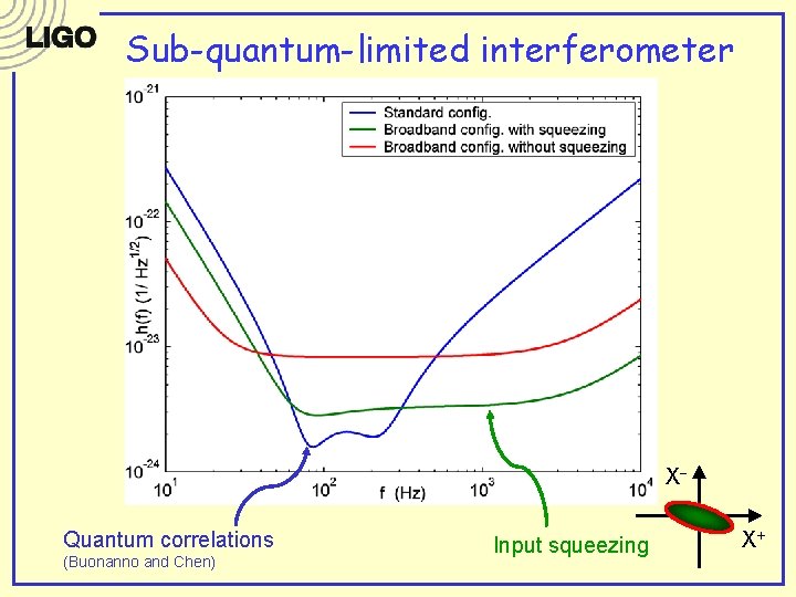
Sub-quantum-limited interferometer XQuantum correlations (Buonanno and Chen) Input squeezing X+
Other emerging detector technologies § Cryogenic suspensions (LCGT Japan) § Broadband (white light) interferometers (Hannover, UF) § All-reflective interferometers (Stanford) § Reshaped laser beam profiles (Caltech) § Quantum non-demolition § Evade measurement back-action by measuring of an observable that does not effect a later measurement § Speed meters (Caltech, Moscow, ANU) § Optical bars (Moscow) § Correlations between the SN and RPN quadratures