ADVANCED EMISSIONS AND ONBOARD DIAGNOSTICS OBD OBJECTIVES Describe
")
ADVANCED EMISSIONS AND ONBOARD DIAGNOSTICS (OBD)

OBJECTIVES • Describe the operation of on-board diagnostic systems • Explain the differences between OBD I and OBD II • Interpret OBD II scan tool data • Describe the operation of OBD II monitors • Use a scan tool to verify the running of various OBD II monitors

INTRODUCTION • Government involvement in emission controls and fuel economy • Drives technology advancement • Objective of modern on-board diagnostics • • • Air-quality improvement • 1996: closed loop achieved at 68°F with OBD II within seconds of startup 90% of emissions occur during warm-up Early computer-controlled: required 176°F to achieve closed loop

HISTORY OF ON-BOARD DIAGNOSTICS • 1988: OBD I legislation began with cars sold in California • California has toughest emission laws • Since 1994: air quality in Los Angeles basin has been improving • Today OBD legislation national • 1997: OBD II required on all cars built in U. S.

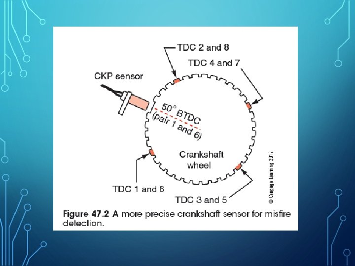
OBD II OPERATION • OBD II detects exhaust and evaporative emissions in excess of 1. 5 times FTP • FTP measures emission in grams per mile • Hydrocarbon, carbon monoxide, and oxides of nitrogen • Extra hardware is required • • Heated O 2 sensor and misfire detection capability 16 -pin data link connector Evaporative system monitor Positive crankcase ventilation (PCV) monitor
 STANDARDS • Standard communication protocol • Specifies protocol used")
SOCIETY OF AUTOMOTIVE ENGINEERS (SAE) STANDARDS • Standard communication protocol • Specifies protocol used to communicate between computer and scan tool • Standardization of terms • Lists common names for all components that serve a similar purpose • Standard diagnostic connector • Requires a universal DLC for reading DTCs • Generic scan tool • Scan tool used on different makes of vehicles
 STANDARDS (CONT'D. ) • Standard diagnostic trouble codes •")
SOCIETY OF AUTOMOTIVE ENGINEERS (SAE) STANDARDS (CONT'D. ) • Standard diagnostic trouble codes • SAE J 2012: SAE-approved list of generic DTCs • Common diagnostic test modes • • Scan tools have global and enhanced portions Enhanced side requires VIN input • • Includes manufacturer-specific menus and data Global is generic • • Includes 15 modes Only modes one through nine are used

TROUBLE CODES AND THE MALFUNCTION INDICATOR LAMP • MIL must illuminate if emissions exceed 1. 5 times the federal standard • • OBD II deals only with emission codes Generic scan tool might read 50 fault codes • • • Manufacturer’s tool might read hundreds DTC is stored in computer’s non-volatile RAM Warm-up cycle occurs every time the engine cools off and temperature rises 40°F • Code erased after 40 warm-up cycles
 • Trip requires ignition switch")
TROUBLE CODES AND THE MALFUNCTION INDICATOR LAMP (CONT'D. ) • Trip requires ignition switch to be off for a while • Emission control monitors operate to complete one trip • Enabling criteria include monitors • • • Engine misfire and catalyst efficiency Fuel system O 2 sensor EGR Evaporative system Air injection
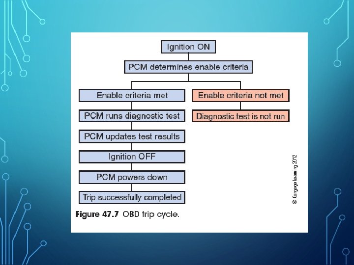
 • During drive cycle engine")
TROUBLE CODES AND THE MALFUNCTION INDICATOR LAMP (CONT'D. ) • During drive cycle engine must enter closed loop • All trip monitors must operate • Same fault must be detected during two drive cycles to light MIL • • First time DTC enable criteria are met: pending code is set Second consecutive occurrence of the fault illuminates the MIL • Some scan tools read pending codes

OBD II CODES • DTCs have five characters • • First character: letter that identifies the area of the vehicle • Third character: one to eight represents vehicle subsystem • Last tow characters: represent the fault code Second character: zero is generic and one is assigned by manufacturer
 • Expanded numbers • P 2 XXX and P")
OBD II CODES (CONT'D. ) • Expanded numbers • P 2 XXX and P 3400–P 3999 • Types of DTCs • Two emission related and two are not • OBD are separate programs within the computer • Computer decides which signals are rational

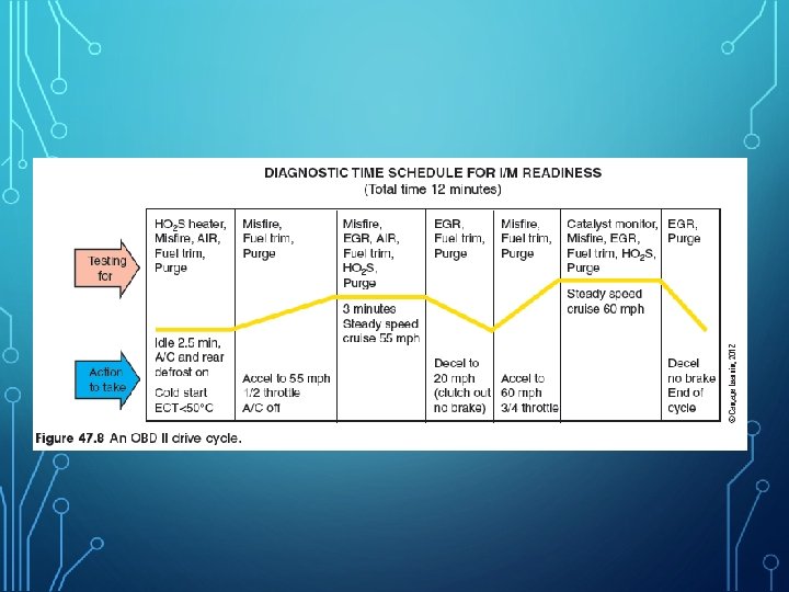
OBD II DIAGNOSTIC TESTING • Monitors look for malfunctions • • Continuous: operates when engine runs Non-continuous: tests once per drive cycle • Readiness indicators • Tell if OBD II monitors completed since KAM last cleared • Incomplete monitors result in failed test
 • Monitor tests • Comprehensive component monitor •")
OBD II DIAGNOSTIC TESTING (CONT’D. ) • Monitor tests • Comprehensive component monitor • • • Evaporative emission leak check monitor • • • Continuous monitor Looks at electrically controlled emissions devices No leaks larger than end of a ballpoint pen Done by pressure or by vacuum EGR monitor • Checks electronic components that direct vacuum or measure opening of the EGR valve
 • Fuel trim monitor • • • Operates")
OBD II DIAGNOSTIC TESTING (CONT’D. ) • Fuel trim monitor • • • Operates continuously when fuel system in closed loop Compares fuel trim to O 2 sensor signal Heated oxygen sensor monitor • Changes the injector pulse width while checks upstream oxygen sensor • Checks for fast enough oscillating frequency
 • Sensor identification • • Oxygen sensor heater")
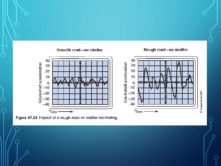
OBD II DIAGNOSTIC TESTING (CONT’D. ) • Sensor identification • • Oxygen sensor heater monitor • • • Tested electronically Tests right away in drive cycle Misfire detection monitor • • O 2 sensor is identified by code resulting from monitor test Continuously detects when engine slows momentarily due to misfire Type A misfires • PCM is more likely to flash the MIL
 • Type B misfires • • • Secondary")
OBD II DIAGNOSTIC TESTING (CONT’D. ) • Type B misfires • • • Secondary air injection monitor • • • Typical monitor allows two- to three-percent random misfiring After one more drive cycle, a code is set Higher engine compression increases NOX, which provides more O 2 for conversion in the cat Test is done at startup when air is needed Thermostat monitor • • Used since 2000 model year Enabled in drive cycle after engine is off two hours
 • Positive crankcase ventilation system monitor • •")
OBD II DIAGNOSTIC TESTING (CONT’D. ) • Positive crankcase ventilation system monitor • • Required since 2004 model year Detects disconnected, damaged hose, or restriction in hose or valve Catalytic converter monitor • Other monitors must run before catalytic converter monitor runs • Detects switch ratio Mode $06 Data • • Tells which tests have been run Test results

EMISSION TESTING PROGRAMS • Enhanced testing • Used in areas with higher smog levels • Rich or lean conditions must be addressed before diagnosing NOX failures • Lean air-fuel ratio increases NOX when it causes preignition • Rich mixture does not increase NOX but resulting misfire increases CO • O 2 S must be fast enough in repeated transitions from rich to lean and must be within calibration
 • Propane enrichment test • • • Run at")
EMISSION TESTING PROGRAMS (CONT'D. ) • Propane enrichment test • • • Run at 2, 000 -2, 500 rpm for one second Shut off propane while system is still rich DSO reading should flat line lean Inject a quick burst of propane while pattern is lean Voltage should rise from lean to full rich in less than 100 ms
- Slides: 24