ADDRESSING MODES INSTRUCTIONS SET OF 8051 MICRO CONTROLLER


 n Code access (ROM access) Using")

 Data access (RAM access) n Using")


- Slides: 37
ADDRESSING MODES & INSTRUCTIONS SET OF 8051 MICRO CONTROLLER
Addressing modes v Definition: - The different ways in which a source operand in an instruction are known as the addressing modes. The 8051 provides a total of 5 distinct addressing modes.
Types of Addressing modes Immediate Addressing mode Register Addressing mode Direct Addressing mode Register indirect Addressing mode Indexed Addressing mode
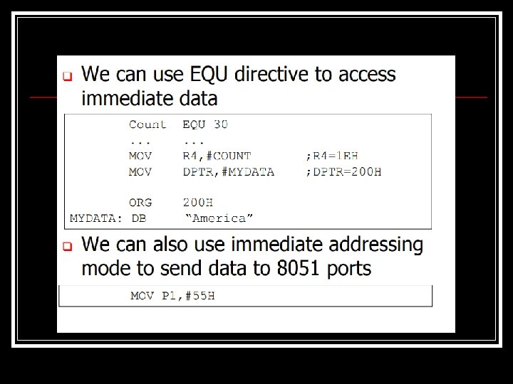
Immediate addressing mode In this addressing mode the source operand is constant. In immediate addressing mode, when the instruction is assembled, the operand comes immediately after the op-code.
Continue… § The immediate data preceded by ‘#’ sign. must be § This addressing mode can be used to load information into any of the register, including the DPTR.
Continue… § Ex : MOV A, #25 H MOV R 4, #62 // load 25 H in to A // load the decimal value 62 into R 4. MOV DPTR, #4532 H // DPTR=4532 H.
Register addressing mode involves the use of registers to hold the data to be manipulated.
Continue… Ø Ex : MOV A, R 0 // copy the contents of R 0 in to A. MOV R 2, A // copy the contents of A in to R 2. ADD A, R 5 // add the content of R 5 to content of A.
Direct addressing mode In direct addressing mode, the data is in a RAM memory location whose address is known, and this address is given as a part of the instruction. Contrast this with the immediate addressing mode in which the operand itself is provided with the instruction.
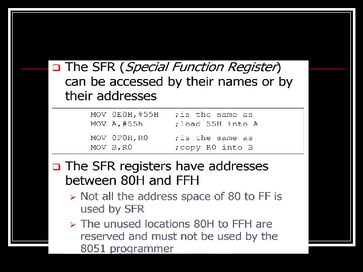
Direct addressing mode n In this mode the operand is specified by an 8 -bit address field In the instruction. n One can access all the 128 bytes of internal RAM locations and each SFR. n If the MSB bit = 0 then the location is within on chip internal RAM. If MSB bit = 1 then the location is SFR. 12
Direct addressing mode The location 00 h to 7 Fh to address the internal RAM. n SFR addresses from 80 h to FF h n n e. g. MOV A, 40 h MOV R 0, 14 h 13
Continue… Ø Ex: MOV R 0, 40 H // save content of RAM location 40 h into R 0. MOV 56 H, A // save content of A in RAM location 56 H.
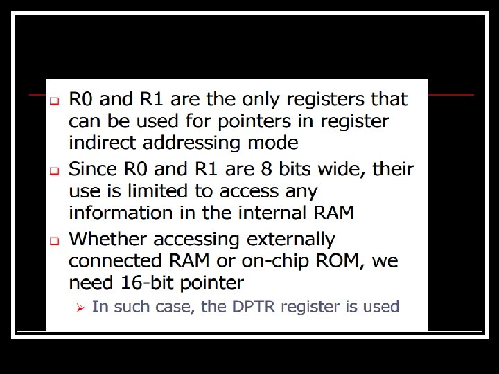
Register indirect addressing mode In the register indirect addressing mode, a register is used as a pointer to the data. n If the data is inside the CPU, only register R 0 and R 1 are used for this purpose. n In other words, R 2 -R 7 cannot be used to hold the address of an operand located in RAM when using this addressing mode. n
Continue… When R 0 and R 1 are used as pointers , that is, when they hold the address of RAM locations , they must be preceded by the “@” sign. Note : only register R 0 and R 1 can be used for indirect addressing mode. MOV A, @R 2 invalid instruction. Ø
Continue… Ex : MOV A, @R 0 // move contents of RAM location whose address is held by R 0 into A. MOV @R 1, B // move contents of B to RAM location whose address is held by R 1
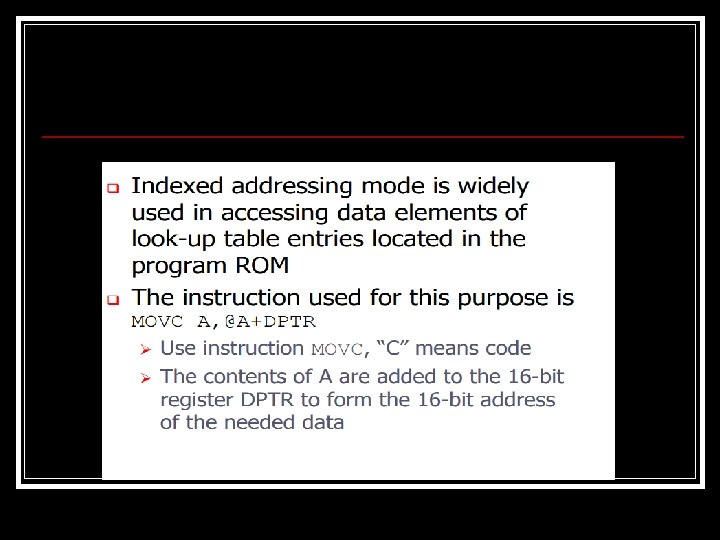
External addressing mode or Indexed addressing mode (a) n Code access (ROM access) Using these instructions only program memory can be accessed. n This addressing mode is preferred for reading look up tables in the program memory. n Either DPTR or PC can be used as pointer. 21
External addressing mode or Indexed addressing mode n E. g. MOVC A, @A+DPTR MOVC A, @A+PC 23
External addressing mode or Indexed addressing mode (b) Data access (RAM access) n Using this addressing mode the programmer can access the external Data memory n E. g. MOVX A, @DPTR MOVX @R 0, A Prof. Nitin Ahire 24
Continue… Ø In this instruction the content of A are added to the 16 -bit register DPTR to form the 16 -bit address of the needed data.
Instruction set of 8051 § § § 8051 has simple instruction set in different groups. There are: Arithmetic instructions Logical instructions Data transfer instructions Branching and looping instructions Bit control instructions
Arithmetic instructions These instructions are used to perform various mathematical operations like addition, subtraction, multiplication, and division etc.
Continue… § § § ADD A, R 1 // Add the content of register 1 to Accumulator ADDC A, #2 // Add 2 to accumulator with carry SUBB A, R 2 // Subtract content of register 2 from Accumulator
Continue… § § INC A DEC A MUL AB DIV AB // // Increment accumulator Decrement accumulator Multiply A and B Divide A by B
Logical instructions n The logical instructions are the instructions which are used for performing some operations like AND, OR, NOT, X-OR and etc. , on the operands.
Continue… ANL A, Rn // AND register to accumulator n ORL A, Rn // OR register to accumulator n XRL A, Rn // Exclusive OR Reg to Acc n CLR A // Clear Accumulator n CPL A // Complement Accumulator n
Data Transfer Instructions n These instruction are used to transfer the data from source operand to destination operand. All the store, move, load, exchange input and output instructions belong to this group.
Continue… MOV A, Rn // Move Reg to Acc n MOVX A, @DPTR // Move external RAM to Accumulator n PUSH direct // PUSH direct byte on to stack n POP direct // POP direct byte from stack n
Branch and Looping Instructions These instructions are used for both branching as well as looping. n These instructions include conditional & unconditional jump or loop instructions. n
Conditional Jump Instructions JC n JNC n JB n JNB n JBC n // Jump if carry equal to one // Jump if carry equal to zero // Jump if bit equal to one // Jump if bit equal to zero // Jump if bit equal to one and clear bit
Continue… JZ n JNZ n DJNZ n // Jump if A=Zero // Jump if A not equal to zero // Decrement and Jump if not equal to zero.
Unconditional Jump Instructions In 8051 there two unconditional jumps. They are: n SJMP // Short jump n LJMP // Long jump n