Addis Ababa University Addis Ababa institute of Technology

Addis Ababa University Addis Ababa institute of Technology SECE By Teshome. H Dec, 2018

Induction motor drives 3. Introduction, Ø AC electric motors are generally: o more compact, o have better efficiency than their DC counterparts. Ø Moreover; they are supplied from commercially available AC power while for DC motors, the AC must be converted to DC at point of use.
")
Cont’d… Ø Conventional AC machines are: o either synchronous machines or o asynchronous (induction) machines Ø Both machines have stator with armature winding and rotor with field winding.

Cont’d… However; o there are permanent magnet synchronous motors which don’t have winding on the rotor; o instead the required field winding coming from the permanent magnets. o In asynchronous (induction) machines, power is supplied only to the armature circuit; ü the rotor circuit is excited through induction.

Cont’d… Ø On the other hand for non permanent magnet synchronous motors, ü the excitation is generally from separate DC power supply. Ø What makes induction motors the most used in industry? o average torque at zero speed, o single power supply requirement and maintenance free operation

*Induction motor types: v Squirrel cage type: ØRotor winding is composed of copper bars embedded in the rotor slots and shorted at both end by end rings ØSimple, low cost, robust, low maintenance

v Wound rotor type: ØRotor winding is wound by wires. The winding terminals can be connected to external circuits through slip rings and brushes. ØEasy to control speed, more expensive.

3. 1. Induction motor equivalent circuit and the torque-speed curve Ø The equivalent circuit development can be seen in two steps. ü The first step is looking the rotor not to rotate so that the induction machine is like a transformer with air-gap in the magnetic circuit. ü The second step is allowing the rotor to rotate.
 Ø If the rotor of an induction motor")
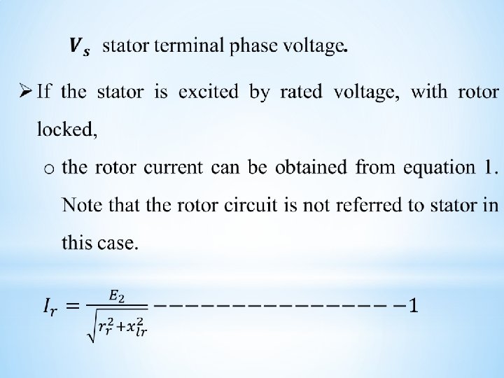
Locked Rotor (Rotor does not rotate) Ø If the rotor of an induction motor is locked (not to rotate), o its equivalent circuit is similar to that of a three phase balanced transformer as shown in figure 1.

Cont’d……… Fig. 1 Induction motor equivalent circuit when rotor is locked with rotor circuit referred to stator

Actual rotor resistance Resistance equivalent to mechanical load

Cont’d…
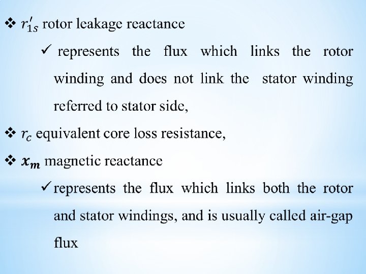

Cont……… ØWhere E 2 is induced e. m. f. in rotor, ü Ir is rotor current, ü rr rotor winding resistance, ü xlr is rotor leakage inductance.

Cont’d……… Ø The rotor circuit parameters and variables can be referred to stator circuit as shown in figure 1 b. o The referred rotor current can also be expressed as in equation 1. o The apostrophe indicating referred parameters to stator circuit (functions of turn’s ratio between stator and rotor)

Rotor Rotating With Slip s

Ø Therefore, there will be induced voltage in the rotor winding whose frequency is only sf Hz, o Hence, the induced voltage in the rotor will be s. E 2 while the reactance is sxlr. o Equation 2, then, can be used to calculate rotor current assuming the induced voltage and reactance equal to the ones when the rotor is at stand still (similar to transformer), and only the rotor resistance changing with slip s.
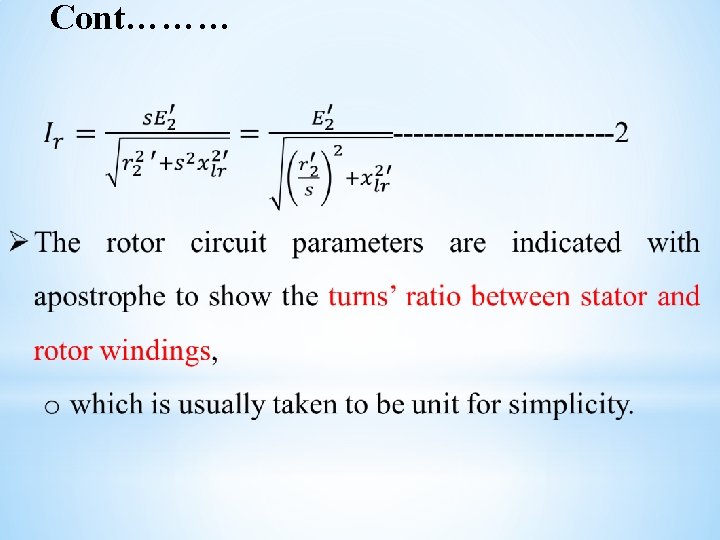

Figure 2 Induction motor equivalent circuit when rotor is rotating at slip s

Cont’d… Ø Equivalent circuit of figure 2 can be approximated by figure 3: o if the voltage drop across stator winding resistance is neglected. nd a al c i tr ers c e El gine f e o s En t tu nic i t Ins ctro Ele Figure 3 Approximate (IEEE) equivalent circuit of induction motor

Power Flow in induction motor
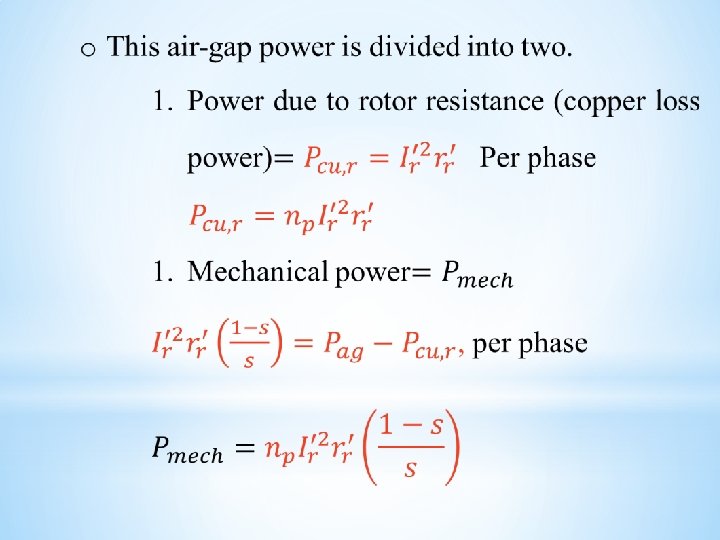
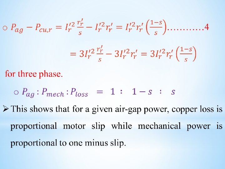

Ø mechanical power = output shaft power + mechanical windage and frictional losses.

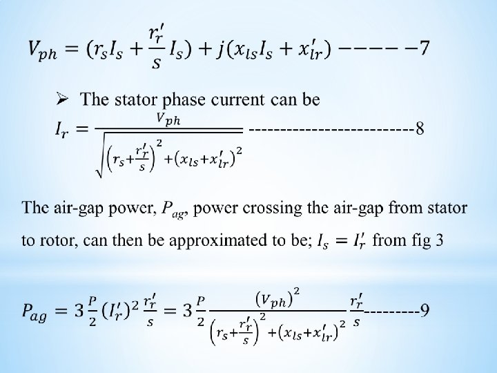
ØThe torque-speed characteristics of a balanced threephase induction motor can be derived from the equivalent circuit of the motor replacing the rotor current in equation 6 in terms of terminal voltage. ØConsider the simplified equivalent circuit given in Fig. 3 for rotor current estimation ØThe phase voltage can be written as equation 7, from the simplified equivalent circuit neglecting the magnetization current.

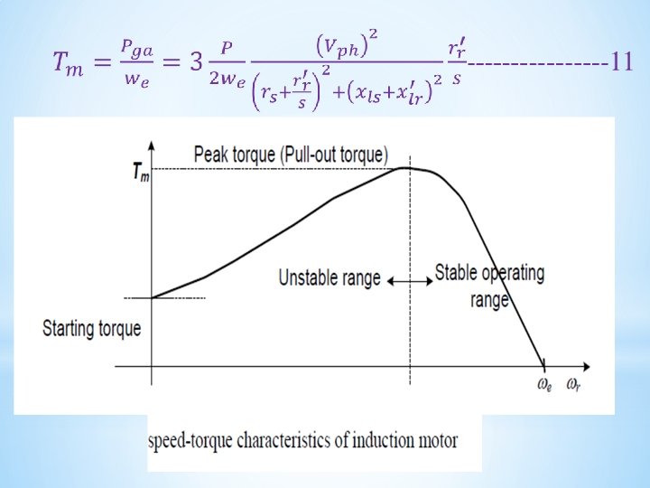
Ø The mechanical power can be expressed as follows, o with rotor current approximated by the terminal voltage divided by impedance. Ø The torque the motor generates is the mechanical power divided by the rotor speed, wr, o which can be written in terms of the electrical synchronous speed, we.
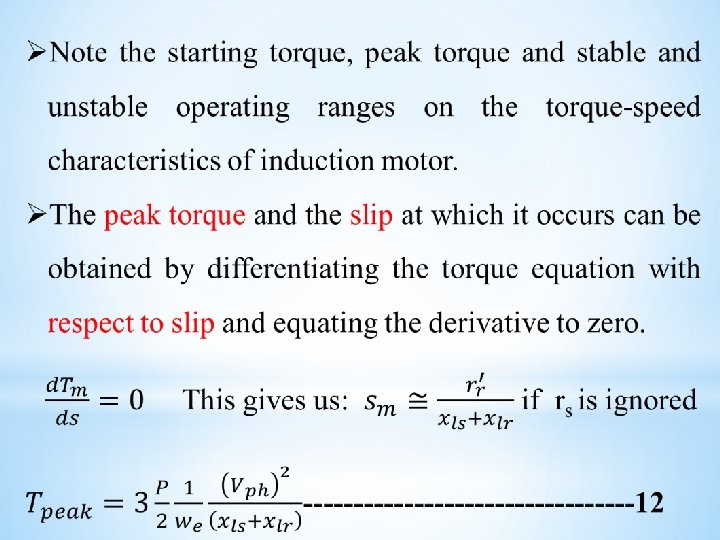

Ø Similarly, the starting torque can be determined by: o equating the slip to be unity corresponding to zero speed. Ø Note in this equations that the peak torque is not function of rotor resistance while the slip at which the peak torque occurs is function of the rotor circuit resistance.

3. 2. Induction motor Speed control Ø The speed of induction motor can be controlled by controlling: o external resistor in the rotor circuit (wound type motor only), o phase voltage, o frequency of supply voltage, o number of poles of the motor, o simultaneous voltage and frequency control.

3. 2. 1. Supply Voltage Control Ø In equation for torque, o if slip is kept constant, o the torque becomes proportional to voltage squared. o The supply voltage decrease results the torquespeed curve as shown in figure below
")
(where Vn>V 1>V 2>V 3)

Ø As the voltage decreases the torque decreases as square of the voltage as shown in the figure. Ø Disadvantage of speed control by supply voltage control are: - o Decrease in peak torque as the square function of the voltage o Decrease in stability of the motor, for the same torque change the speed change is larger for low voltage than higher voltage.

o Decrease in starting torque as voltage decreases, o Difficulty of varying AC supply voltage o The speed adjustment range is limited to between rated and the speed at which the peak torque occurs.

3. 2. 2. External Rotor resistance variation Ø Motor speed variation by external rotor resistance variation : o possible only for wound type induction motors, o because the rotor winding terminals are brought out through slip rings for external resistor connection if required.

o In cage type rotors, there is no access to the rotor winding for external resistance connection. Ø As the peak torque is independent of rotor resistance, it will also independent of external resistor

The resulting torque-speed curve as the rotor circuit resistance varies is drawn

Ø Advantage of induction motor speed control by external rotor resistance variation are: - o The speed range can vary between zero speed and the rated speed o The starting torque increase o The peak torque remains constant Ø On the other hand, its main disadvantages are: o High power loss in the rotor circuit as the result of slip increase for low speeds o Stability decrease as rotor external resistance increases

3. 2. 3. Supply Voltage Frequency Control

o This method is not widely used. o This method is used where, only the induction motor is supplied by the generator (so that frequency can be easily changed by changing the speed of the prime mover) o By changing the frequency, we can control the speed above and below the rated speed. o It offers high range of speed control
")
speed control by supply frequency control (fn>f 1>f 2)

Ø Advantages speed controls by supply frequency control are: - o The speed control range can extend from rated speed to zero speed Ø Main disadvantage of frequency control method: o the stator current increases and results overloading as the frequency decreases. o This is the result of reactive impedance decrease as the frequency decreases.

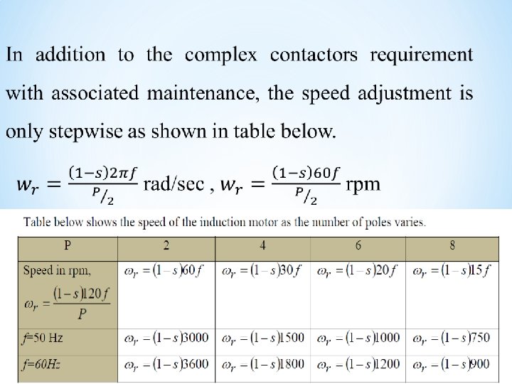
3. 2. 4. Changing number of poles Ø The terminals of all the windings have to be brought out for proper connection using magnetic contactors or circuit breakers. Ø Such pole adjustments are usually limited to two or three steps due to the complication and cost of switching. Ø The rotor is always cage type, which adjusts its self, automatically to stator number of poles.

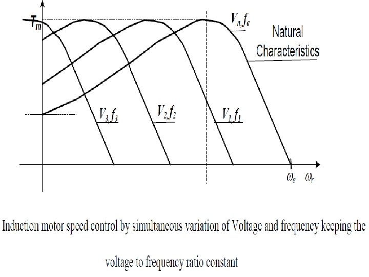
3. 2. 5. Speed Control by varying frequency and voltage Ø voltage to frequency ratio is constant. Ø Simultaneous control of voltage and frequency for constant ratio of the two. Ø This method results : o a constant peak torque, o roughly constant stability level, and o wide speed control range.

üMaintain speed regulation üuses power electronics circuit for frequency and voltage controller
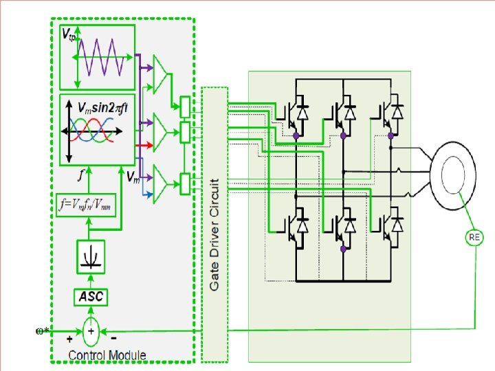

Ø The induction motor speed control by simultaneous variation of voltage and frequency, o keeping the ratio of voltage to frequency constant is possible: o if the motor is to be supplied by an inverter which can control both the frequency and the magnitude of the voltage output to the motor. o In this control the air gap flux is approximately kept constant.

o ASC represents the automatic speed controller which can be any controller like: o Proportional-Integral (PI), o Proportional-Integral-Derivative (PID) and the like.

o The hyperbolic function represents the torque voltage relation, o Torque being proportional to voltage squared for a constant slip as shown in equation below. Ø Once the voltage is obtained from this relation, the frequency can be obtained from the constant voltage to frequency ratio at rated value.

Ø Where, Vmn and fn are, respectively, rated voltage and rated frequency. Ø Characteristics of constant voltage to frequency ratio control are: o Constant peak torque, o Constant relative stability, o Approximately constant copper loss o Wide speed control range between zero and rated speed

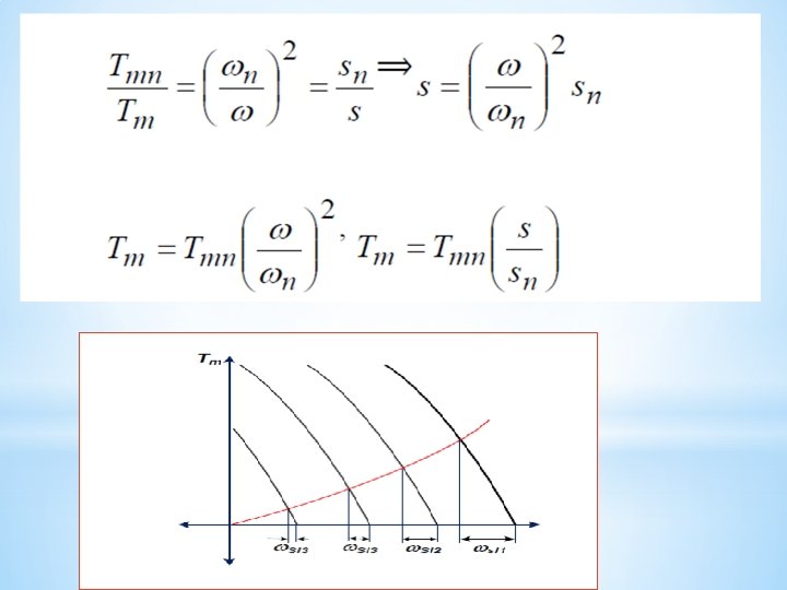
3. 2. 6. Small slip torque-speed relation Ø If load torque is proportional to speed squared as shown in figure below, the torque to slip ratio can be given as shown below.
 Ø A variable frequency drive converts")
Inverter supplied Induction motor Variable Speed Drive (VSD) Ø A variable frequency drive converts incoming 50 Hz utility power into DC, then converts to a simulated variable voltage, variable frequency output. Ø Applies to devices that control the speed of : • either the motor or • the equipment driven by the motor ü (fan, pump, compressor, etc. )
 AC INVERTER (DC - AC) Zero - 100")
AC DC RECTIFIER (AC - DC) AC INVERTER (DC - AC) Zero - 100 Hz 50 Hz VFD 50 Hz Power ABB To Motor Zero - 100 Hz Electrical Energy VFD consists of the following stages: ü rectifier stage ü Inverter stages ü control
 and a variable speed drive (VSD)")
The differences between a variable frequency drive (VFD) and a variable speed drive (VSD) ü A variable frequency drive (VFD) refers to: o AC drives only and o vary the speed of an AC motor by varying the frequency to the motor. ü A variable speed drive (VSD) refers to: o either AC Drives or DC Drives. o VSDs referring to DC motors vary the speed by varying the voltage to the motor.
 2. Voltage source Inverter(VSI) 3. pulse width modulation")
* 1. current source inverter (CSI) 2. Voltage source Inverter(VSI) 3. pulse width modulation (PWM) 1. current source inverter (CSI) ü Consists of large and expensive inductor so to gives smooth current 2. Voltage source Inverter(VSI) ü Have poor power factor 3. pulse width modulation (PWM) ü most widely used, because of good power factor and less cost

Positive DC Bus Negative DC Bus + - RECTIFIER INVERTER

Positive DC Bus Negative DC Bus + - RECTIFIER INVERTER

Positive DC Bus Negative DC Bus + - RECTIFIER INVERTER

Positive DC Bus Negative DC Bus + - RECTIFIER INVERTER

Positive DC Bus Negative DC Bus + - RECTIFIER INVERTER

Positive DC Bus Negative DC Bus + - RECTIFIER INVERTER

Positive DC Bus Negative DC Bus + - RECTIFIER INVERTER

Positive DC Bus Negative DC Bus + - RECTIFIER INVERTER

Positive DC Bus Negative DC Bus + - RECTIFIER INVERTER

Positive DC Bus Negative DC Bus + - RECTIFIER INVERTER

Positive DC Bus Negative DC Bus + - RECTIFIER INVERTER

Positive DC Bus Negative DC Bus + - RECTIFIER INVERTER

Positive DC Bus Negative DC Bus + - RECTIFIER INVERTER

Positive DC Bus Negative DC Bus + - RECTIFIER INVERTER

Positive DC Bus Negative DC Bus + - RECTIFIER INVERTER

Positive DC Bus Negative DC Bus + - RECTIFIER INVERTER

Positive DC Bus Negative DC Bus + - RECTIFIER INVERTER

Positive DC Bus Negative DC Bus + - RECTIFIER INVERTER

Positive DC Bus Negative DC Bus + - RECTIFIER INVERTER

Positive DC Bus Negative DC Bus + - RECTIFIER INVERTER

Positive DC Bus Negative DC Bus + - RECTIFIER INVERTER

Positive DC Bus Negative DC Bus + - RECTIFIER INVERTER

Positive DC Bus Negative DC Bus + - RECTIFIER INVERTER

Positive DC Bus Negative DC Bus + - RECTIFIER INVERTER

Positive DC Bus Negative DC Bus + - RECTIFIER INVERTER

Positive DC Bus Negative DC Bus + - RECTIFIER INVERTER

Positive DC Bus Negative DC Bus + - RECTIFIER INVERTER

Positive DC Bus Negative DC Bus + - RECTIFIER INVERTER

Area Under The Square-Wave Pulses Approximates The Area Under A Sine Wave + Voltage Positive DC Bus Negative DC Bus - RECTIFIER INVERTER Frequency

Frequency = 30 Hz Frequency = 60 Hz

RECTIFIER Positive DC Bus Negative DC Bus INVERTER + - Motor

RECTIFIER Positive DC Bus Negative DC Bus INVERTER + - Motor

RECTIFIER Positive DC Bus Negative DC Bus INVERTER + - Motor

RECTIFIER Positive DC Bus Negative DC Bus INVERTER + - Motor

RECTIFIER Positive DC Bus Negative DC Bus INVERTER + - Motor

RECTIFIER Positive DC Bus Negative DC Bus INVERTER + - Motor

RECTIFIER Positive DC Bus Negative DC Bus INVERTER + - Motor

BLOCK DIAGRAM OF VARIABLE FREQUENCY DRIVE AC LINE POWER VARIABLE FREQUENCY AC VOLTAGE DC LINK Converter CONVERTS 50/60 HZ LINE POWER INTO DC Inverter Control INVERTS DC POWER INTO ADJUSTABLE FREQUENCY AC POWER

INVERTER CONVERTER Dc capacitors

converter Converts AC power to DC power DC Bus = RMS x 1. 414

* DC Bus *FILTERS THE VOLTAGE *STORES POWER FOR LOAD

Inverter * *Inverts the DC Bus Voltage into a PWM AC sine wave *Monitors the motor Back EMF to determine the load *Is six set of IGBT or GTO or SCR which converts the dc to variable AC with control system. *The control system maintain the constant ratio of voltage to frequency

Soft Charge Circuit * look as a dead short to the AC line. §The resistor allows the caps to charge softly and prevent fuse faults. Soft charge circuit §At start up the discharged caps
- Slides: 103