
ADC and DAC Programming in AVR Sepehr Naimi

- Slides: 19
ADC and DAC Programming in AVR Sepehr Naimi www. Nicer. Land. com
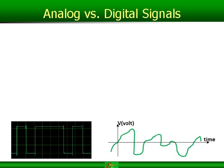
Analog vs. Digital Signals
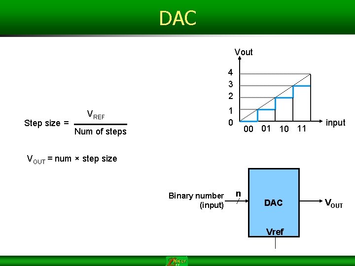
DAC Vout 4 3 2 Step size = 1 0 VREF Num of steps 00 01 10 11 input VOUT = num × step size Binary number (input) n DAC Vref VOUT
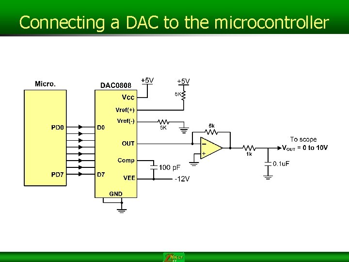
Connecting a DAC to the microcontroller
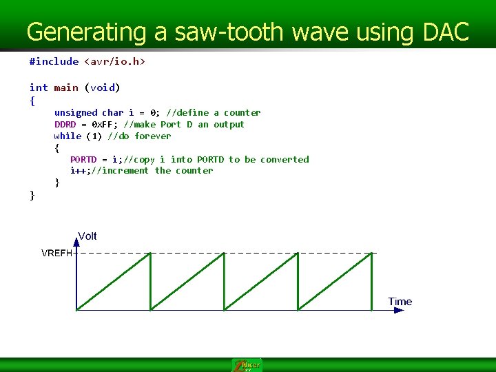
Generating a saw-tooth wave using DAC #include <avr/io. h> int main (void) { unsigned char i = 0; //define a counter DDRD = 0 x. FF; //make Port D an output while (1) //do forever { PORTD = i; //copy i into PORTD to be converted i++; //increment the counter } }
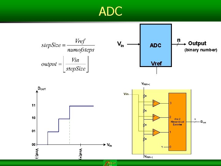
ADC Vin ADC Vref n Output (binary number)
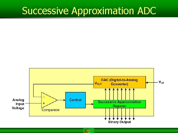
Successive Approximation ADC
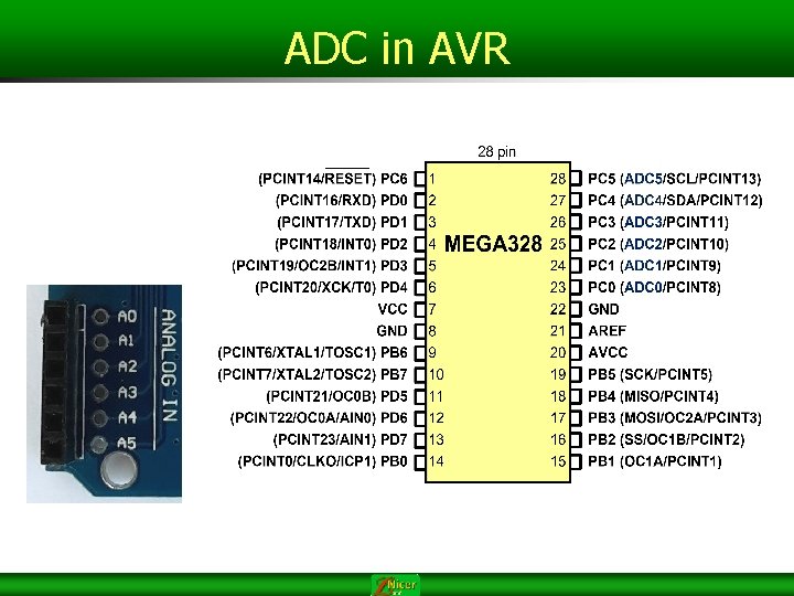
ADC in AVR
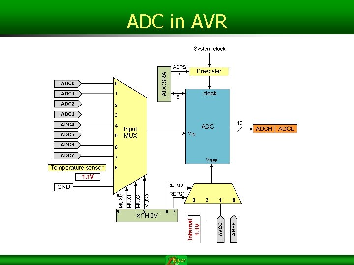
ADC in AVR
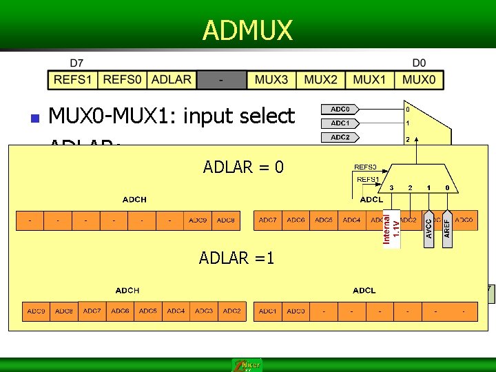
ADMUX n n MUX 0 -MUX 1: input select ADLAR: n n n ADLAR = 0 0: right adjust the result 1: left adjust the result REFS 1 -REFS 0: Vref selection ADLAR =1
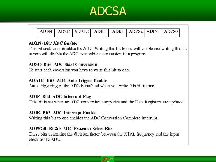
ADCSA
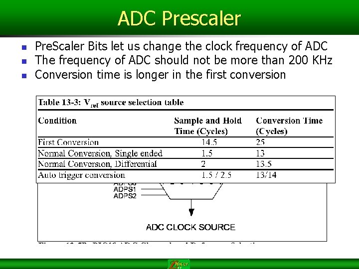
ADC Prescaler n n n Pre. Scaler Bits let us change the clock frequency of ADC The frequency of ADC should not be more than 200 KHz Conversion time is longer in the first conversion
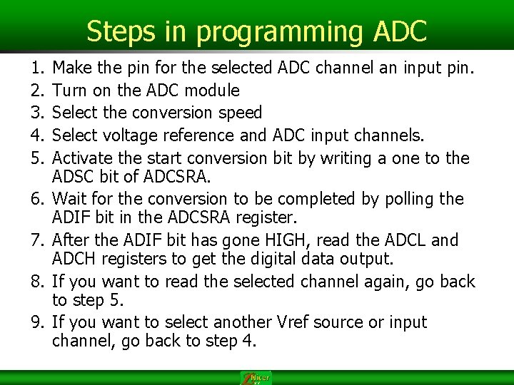
Steps in programming ADC 1. 2. 3. 4. 5. 6. 7. 8. 9. Make the pin for the selected ADC channel an input pin. Turn on the ADC module Select the conversion speed Select voltage reference and ADC input channels. Activate the start conversion bit by writing a one to the ADSC bit of ADCSRA. Wait for the conversion to be completed by polling the ADIF bit in the ADCSRA register. After the ADIF bit has gone HIGH, read the ADCL and ADCH registers to get the digital data output. If you want to read the selected channel again, go back to step 5. If you want to select another Vref source or input channel, go back to step 4.
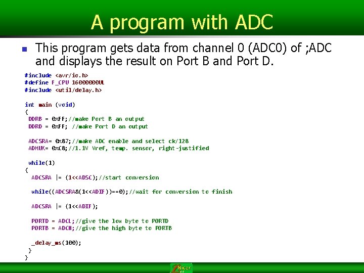
A program with ADC This program gets data from channel 0 (ADC 0) of ; ADC and displays the result on Port B and Port D. n #include <avr/io. h> #define F_CPU 16000000 UL #include <util/delay. h> int main (void) { DDRB = 0 x. FF; //make Port B an output DDRD = 0 x. FF; //make Port D an output ADCSRA= 0 x 87; //make ADC enable and select ck/128 ADMUX= 0 x. C 8; //1. 1 V Vref, temp. sensor, right-justified while(1) { ADCSRA |= (1<<ADSC); //start conversion while((ADCSRA&(1<<ADIF))==0); //wait for conversion to finish ADCSRA |= (1<<ADIF); PORTD = ADCL; //give the low byte to PORTD PORTB = ADCH; //give the high byte to PORTB _delay_ms(100); } }
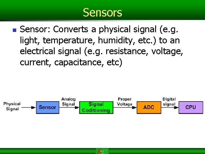
Sensors n Sensor: Converts a physical signal (e. g. light, temperature, humidity, etc. ) to an electrical signal (e. g. resistance, voltage, current, capacitance, etc)
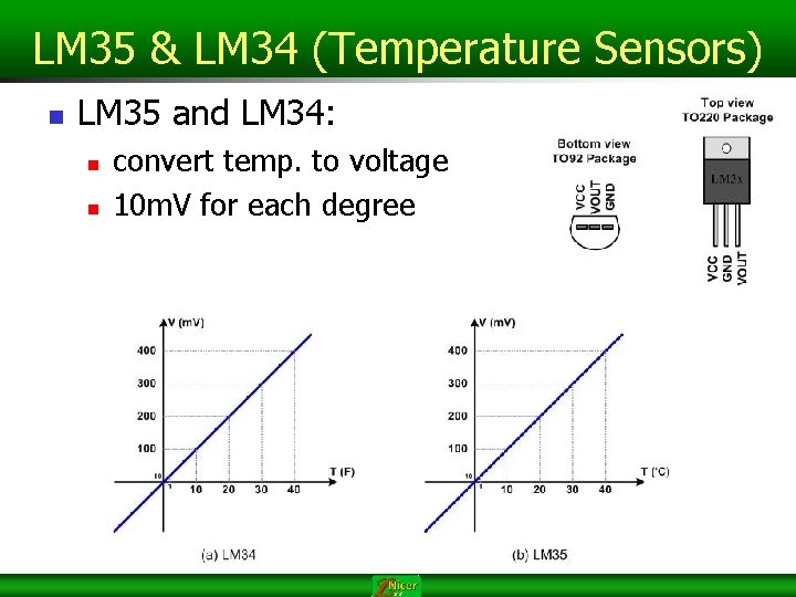
LM 35 & LM 34 (Temperature Sensors) n LM 35 and LM 34: n n convert temp. to voltage 10 m. V for each degree
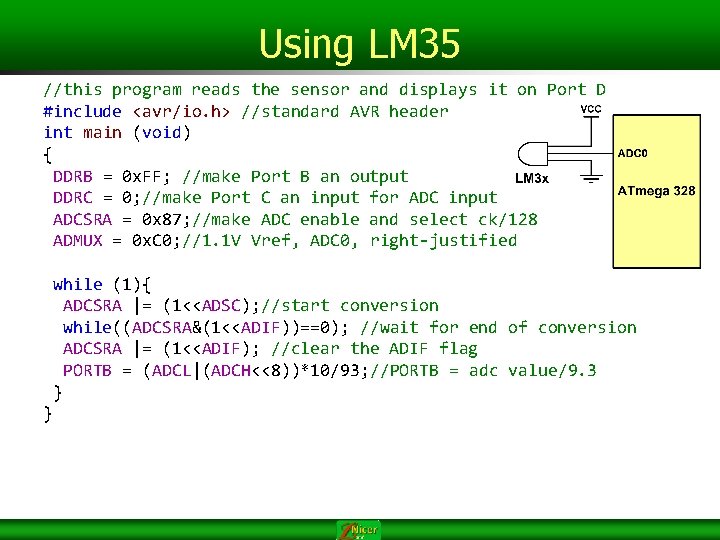
Using LM 35 //this program reads the sensor and displays it on Port D #include <avr/io. h> //standard AVR header int main (void) { DDRB = 0 x. FF; //make Port B an output DDRC = 0; //make Port C an input for ADC input ADCSRA = 0 x 87; //make ADC enable and select ck/128 ADMUX = 0 x. C 0; //1. 1 V Vref, ADC 0, right-justified while (1){ ADCSRA |= (1<<ADSC); //start conversion while((ADCSRA&(1<<ADIF))==0); //wait for end of conversion ADCSRA |= (1<<ADIF); //clear the ADIF flag PORTB = (ADCL|(ADCH<<8))*10/93; //PORTB = adc value/9. 3 } }
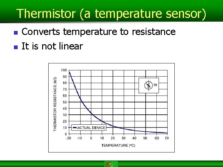
Thermistor (a temperature sensor) n n Converts temperature to resistance It is not linear
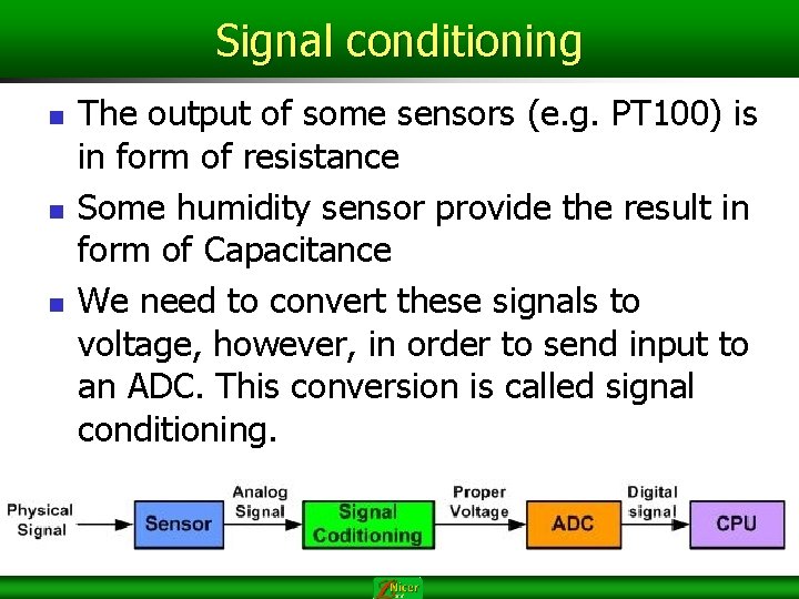
Signal conditioning n n n The output of some sensors (e. g. PT 100) is in form of resistance Some humidity sensor provide the result in form of Capacitance We need to convert these signals to voltage, however, in order to send input to an ADC. This conversion is called signal conditioning.