
Ad Hoc Routing Metrics 15 849 E Wireless


- Slides: 49
Ad Hoc Routing Metrics 15 -849 E -- Wireless Networks 02/27/2006 Kaushik Sheth Jatin Shah
A High-Throughput Path Metric for Multi-Hop Wireless Routing (ETX) Douglas S. J. De Couto, Daniel Aguayo, John Bicket, Robert Morris
Minimum Hop Count • Assumes links either work or don’t work • Minimize hop count -> Maximize the distance traveled by each hop – Minimizes signal strength -> Maximizes the loss ratio – Uses a higher Tx power -> Interference • Arbitrarily chooses among same length paths
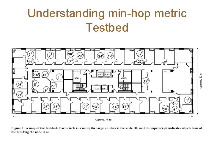
Understanding min-hop metric Testbed
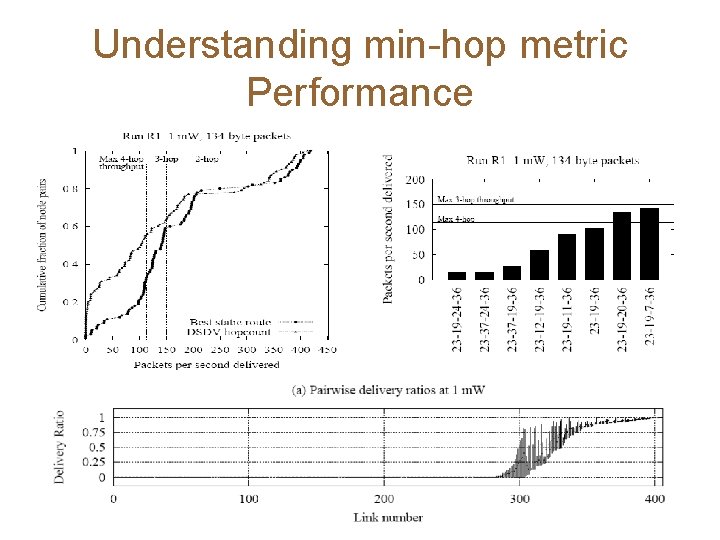
Understanding min-hop metric Performance
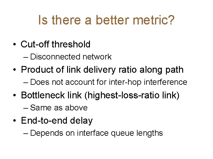
Is there a better metric? • Cut-off threshold – Disconnected network • Product of link delivery ratio along path – Does not account for inter-hop interference • Bottleneck link (highest-loss-ratio link) – Same as above • End-to-end delay – Depends on interface queue lengths
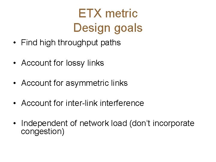
ETX metric Design goals • Find high throughput paths • Account for lossy links • Account for asymmetric links • Account for inter-link interference • Independent of network load (don’t incorporate congestion)
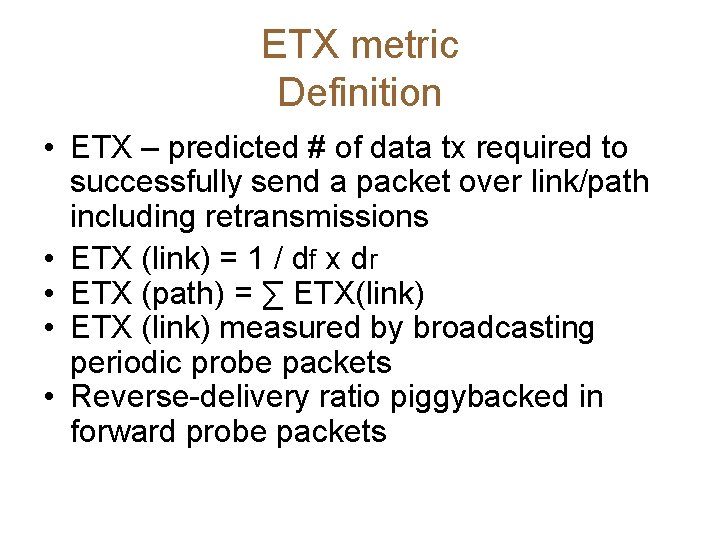
ETX metric Definition • ETX – predicted # of data tx required to successfully send a packet over link/path including retransmissions • ETX (link) = 1 / df x dr • ETX (path) = ∑ ETX(link) • ETX (link) measured by broadcasting periodic probe packets • Reverse-delivery ratio piggybacked in forward probe packets
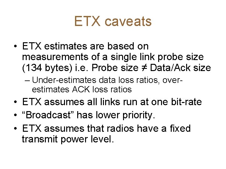
ETX caveats • ETX estimates are based on measurements of a single link probe size (134 bytes) i. e. Probe size ≠ Data/Ack size – Under-estimates data loss ratios, overestimates ACK loss ratios • ETX assumes all links run at one bit-rate • “Broadcast” has lower priority. • ETX assumes that radios have a fixed transmit power level.
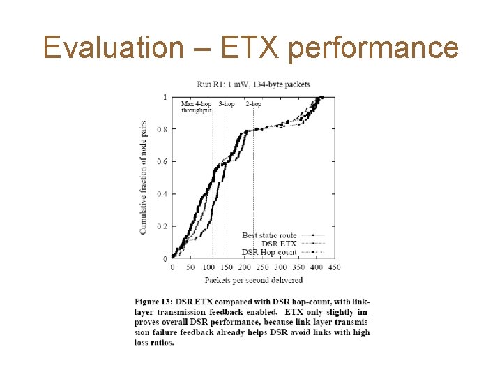
Evaluation – ETX performance
Take aways • Pros – ETX performs better or comparable to Hop Count Metric • Accounts for bi-directional loss rates – Can easily be incorporated into routing protocols as detailed experiments on a real test bed show it • Cons – May not be best metric for all networks • Mobility, Power-limited, Adaptive Rate (multi-rate) – Predications of loss ratios not always accurate as seen in experiments sometimes. – Experiments (30 sec transfer of small packets) may not complement real-world scenarios
Comparison of Routing Metrics for Static Multi-Hop Wireless Networks Richard Draves, Jitendra Padhye and Brian Zill
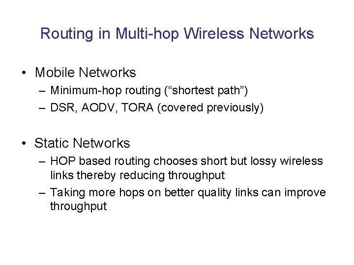
Routing in Multi-hop Wireless Networks • Mobile Networks – Minimum-hop routing (“shortest path”) – DSR, AODV, TORA (covered previously) • Static Networks – HOP based routing chooses short but lossy wireless links thereby reducing throughput – Taking more hops on better quality links can improve throughput
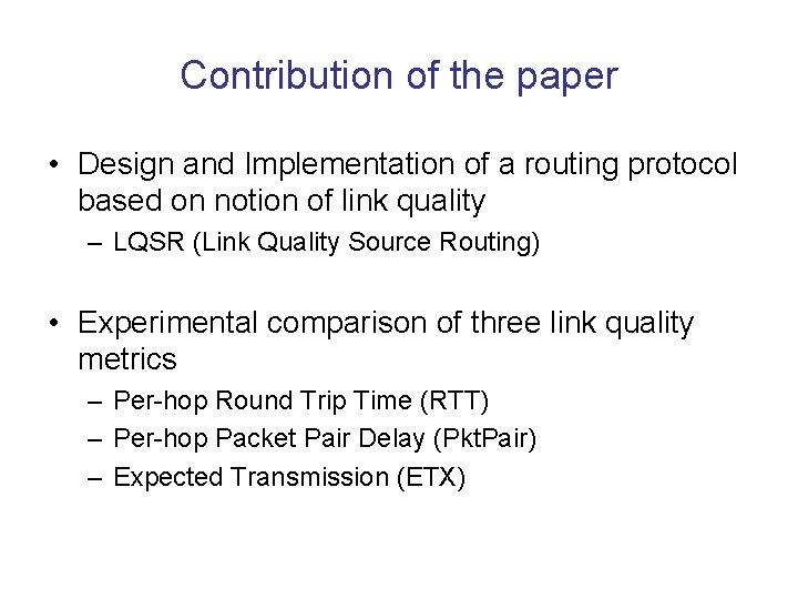
Contribution of the paper • Design and Implementation of a routing protocol based on notion of link quality – LQSR (Link Quality Source Routing) • Experimental comparison of three link quality metrics – Per-hop Round Trip Time (RTT) – Per-hop Packet Pair Delay (Pkt. Pair) – Expected Transmission (ETX)
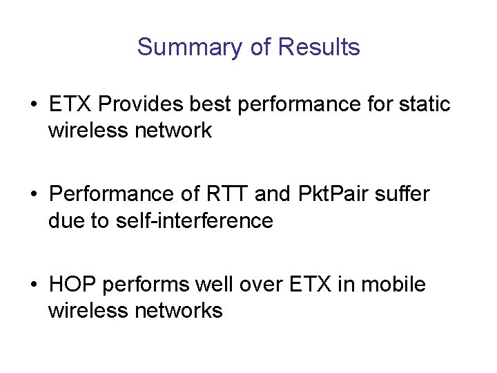
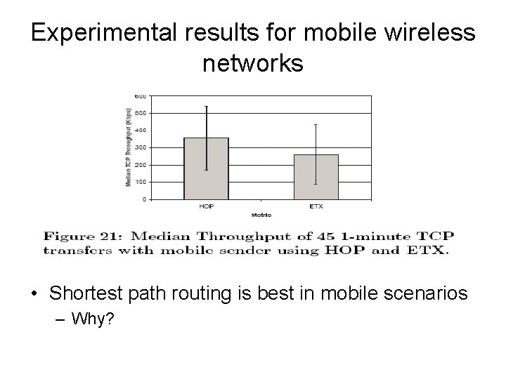
Summary of Results • ETX Provides best performance for static wireless network • Performance of RTT and Pkt. Pair suffer due to self-interference • HOP performs well over ETX in mobile wireless networks
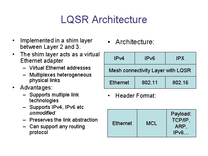
LQSR Architecture • Implemented in a shim layer between Layer 2 and 3. • The shim layer acts as a virtual Ethernet adapter – Virtual Ethernet addresses – Multiplexes heterogeneous physical links • Advantages: – Supports multiple link technologies – Supports IPv 4, IPv 6 etc unmodified – Preserves the link abstraction – Can support any routing protocol • Architecture: IPv 4 IPv 6 IPX Mesh connectivity Layer with LQSR Ethernet 802. 11 802. 16 • Header Format: Ethernet MCL Payload: TCP/IP, ARP, IPv 6…
LQSR • Source Routed, link state protocol – Derived from DSR • Each node measures quality of its link to its neighbor • The info regarding link quality propagates through the mesh • Source selects route with best cumulative metric • Packets are source-routed using this route
Link Quality Metrics • Per-hop Round Trip Time (RTT) – Routing based on minimizing total RTT • Per-hop Packet Pair Delay (Pkt. Pair) – Routing based on minimizing Pkt. Pair • Expected Transmission (ETX) – Routing based on maximizing ETX • Minimum hop routing (HOP) – Routing based on minimizing HOP
Metric 1: Per-hop RTT • Advantages – Easy to implement – Accounts for link load and bandwidth – Also accounts for link loss rate • 802. 11 retransmits lost packets up to 7 times • Lossy links will have higher RTT • Disadvantages – Expensive – Self-interference due to queuing
Metric 2: Per-hop Packet-Pair • Advantages – Self-interference due to queuing is not a problem – Implicitly takes load, bandwidth and loss rate into account • Disadvantages – More expensive than RTT
Metric 3: Expected Transmissions • Advantages – Low overhead – Explicitly takes loss rate into account • Disadvantages – Loss rate of broadcast probe packets is not the same as loss rate of data packets • Probe packets are smaller than data packets • Broadcast packets are sent at lower data rate – Does not take data rate or link load into account
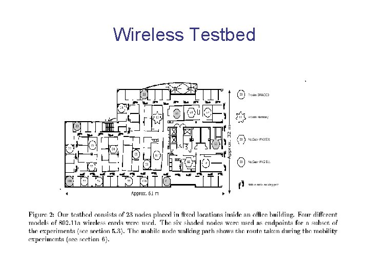
Wireless Testbed
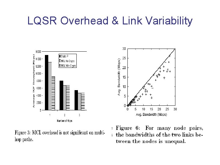
LQSR Overhead & Link Variability
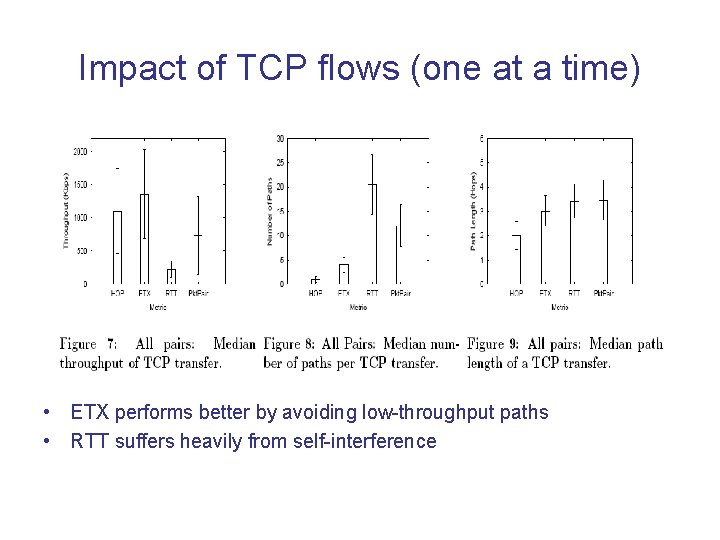
Impact of TCP flows (one at a time) • ETX performs better by avoiding low-throughput paths • RTT suffers heavily from self-interference
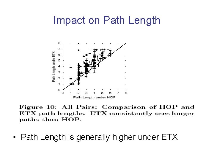
Impact on Path Length • Path Length is generally higher under ETX
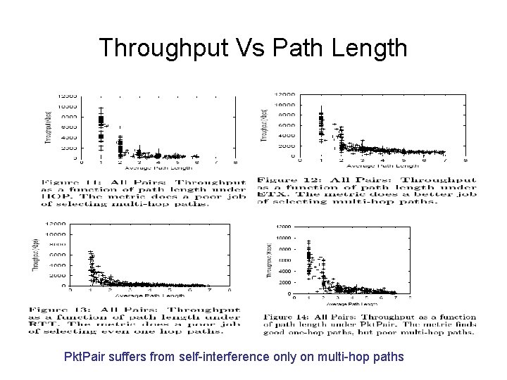
Throughput Vs Path Length Pkt. Pair suffers from self-interference only on multi-hop paths
Experimental results for mobile wireless networks • Shortest path routing is best in mobile scenarios – Why?
Ex. OR: Opportunistic Multi-Hop Routing For Wireless Networks Sanjit Biswas and Robert Morris
Contributions • This paper contributes the first complete design and implementation of a link/network-layer diversity routing technique that uses standard radio hardware. • It demonstrates a substantial throughput improvement and provides insight into the sources of that improvement.
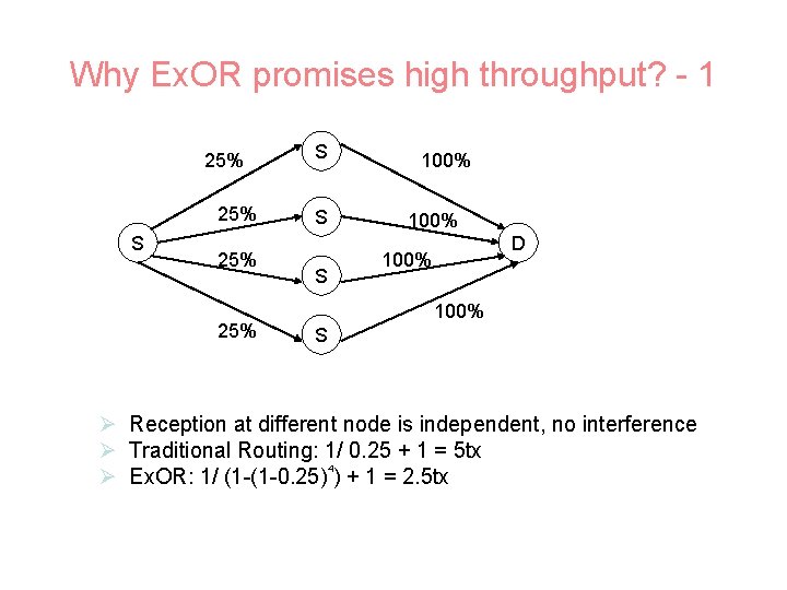
Why Ex. OR promises high throughput? - 1 25% 25% S S S 100% D 100% S Ø Reception at different node is independent, no interference Ø Traditional Routing: 1/ 0. 25 + 1 = 5 tx 4 Ø Ex. OR: 1/ (1 -(1 -0. 25) ) + 1 = 2. 5 tx
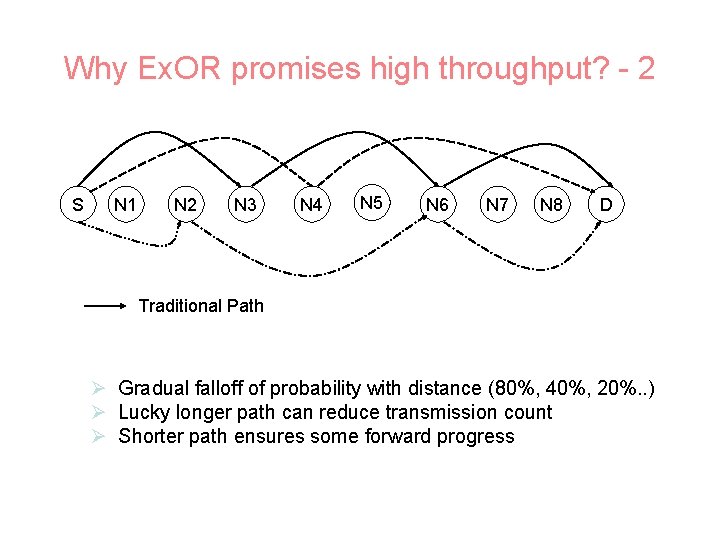
Why Ex. OR promises high throughput? - 2 S N 1 N 2 N 3 N 4 N 5 N 6 N 7 N 8 D Traditional Path Ø Gradual falloff of probability with distance (80%, 40%, 20%. . ) Ø Lucky longer path can reduce transmission count Ø Shorter path ensures some forward progress
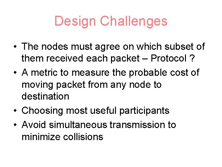
Design Challenges • The nodes must agree on which subset of them received each packet – Protocol ? • A metric to measure the probable cost of moving packet from any node to destination • Choosing most useful participants • Avoid simultaneous transmission to minimize collisions
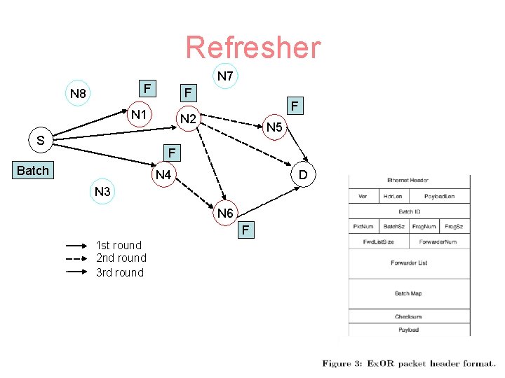
Refresher N 7 F N 8 F N 1 S F N 2 N 5 F Batch N 4 D N 3 N 6 F 1 st round 2 nd round 3 rd round
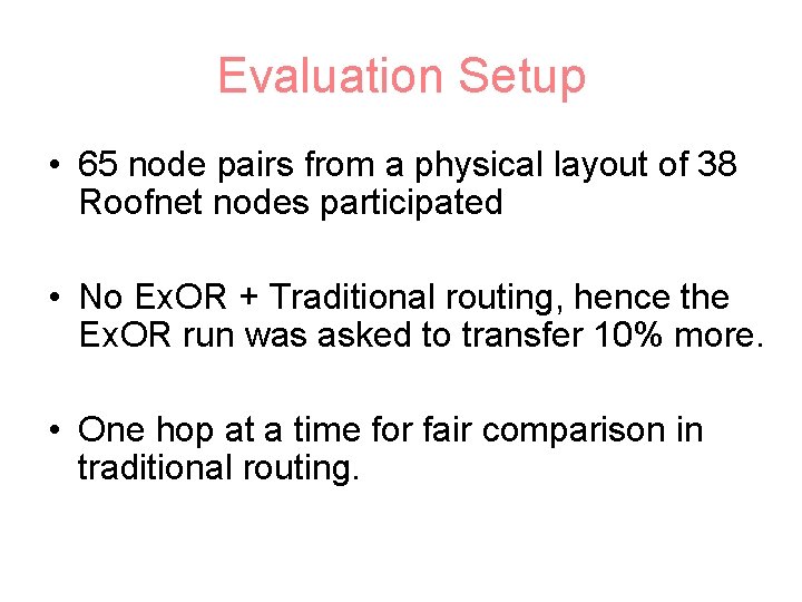
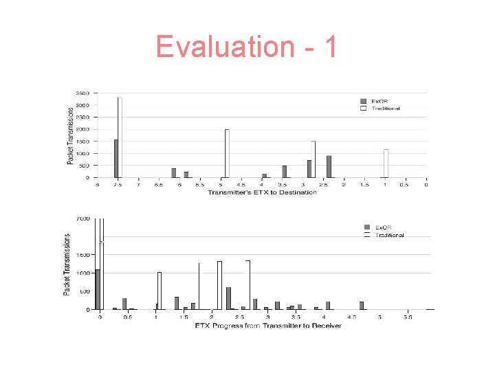
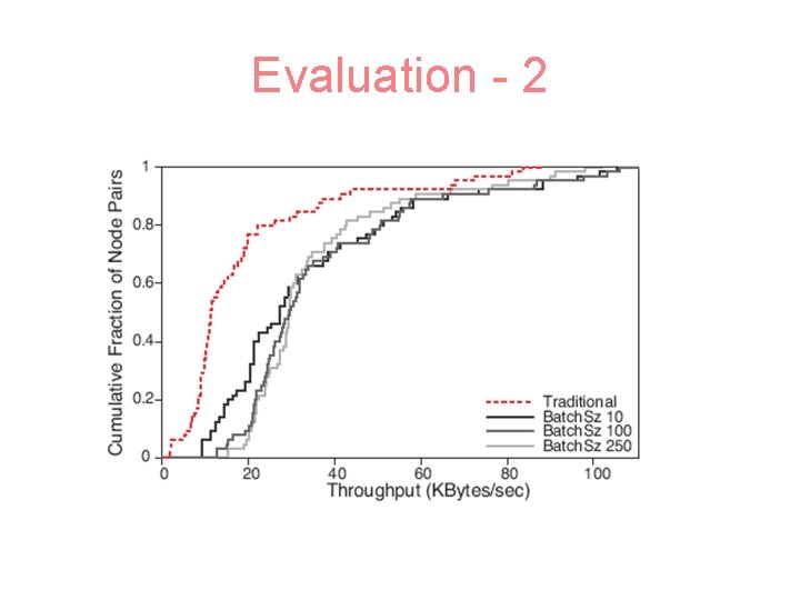
Evaluation Setup • 65 node pairs from a physical layout of 38 Roofnet nodes participated • No Ex. OR + Traditional routing, hence the Ex. OR run was asked to transfer 10% more. • One hop at a time for fair comparison in traditional routing.
Evaluation - 1
Evaluation - 2
Take aways • Pros – Ex. OR achieves 2 x to 4 x throughput improvement for more distant pairs – Ex. OR implemented on Roofnet and evaluated in detail – Exploits radio properties, instead of hiding them – Does not require changes in the MAC layer • Cons – – Not scalable to large network as traditional routing Overhead in packet header (batch info) Batches affect the TCP performance What if not enough packets to make the batch?
Extra –related work • Opportunistic Channel Protocols – Use channel reservation to avoid collisions – Cons: require channel stability, use signal strength to predict reception, does not use intermediate nodes to relay • Opportunistic Forwarding – Select forwarding nodes based on channel conditions – Cons: use channel measurements or distance to predict the delivery success rate • Multiple Path Routing – Maintain multiple routes to use as alternative routes or split the traffic among them – Cons: Ensure the paths are disjoint, need to identify specific paths in advance • Cooperative Diversity Routing – Exploit nearby nodes which overhear the transmission – Cons: duplicate transmissions
A Rate-Adaptive MAC Protocol for Multi-Hop Wireless Networks By Gavin Holland, Nitin Vaidya and Paramvir Bahl
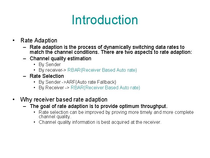
Introduction • Rate Adaption – Rate adaption is the process of dynamically switching data rates to match the channel conditions. There are two aspects to rate adaption: – Channel quality estimation • By Sender • By receiver-> RBAR(Receiver Based Auto rate) – Rate Selection • By Sender ->ARF(Auto rate Fallback) • By Receiver -> RBAR(Receiver Based Auto rate) • Why receiver based rate adaption – The goal of rate adaption is to provide optimum throughput. • Rate selection can be improved by proving more timely and more complete channel quality. • Channel quality information is best acquired at the receiver.
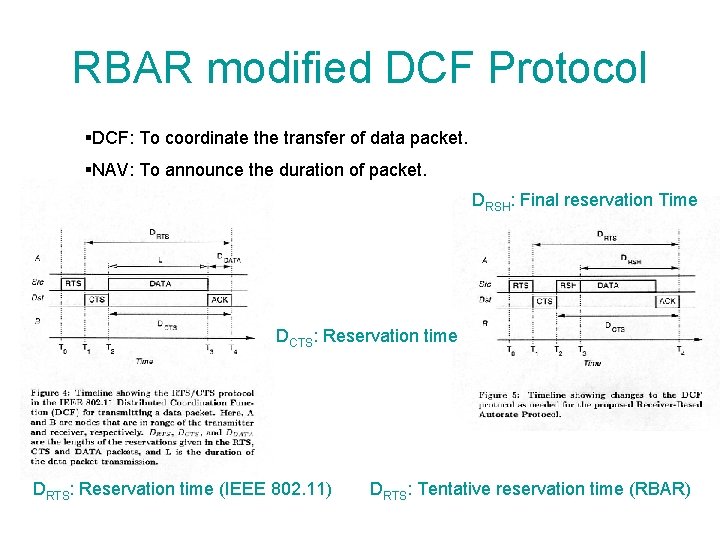
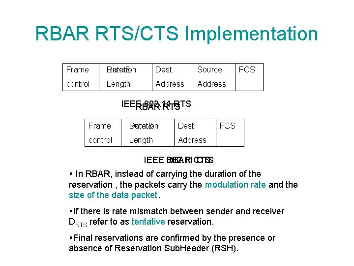
RBAR modified DCF Protocol §DCF: To coordinate the transfer of data packet. §NAV: To announce the duration of packet. DRSH: Final reservation Time DCTS: Reservation time DRTS: Reservation time (IEEE 802. 11) DRTS: Tentative reservation time (RBAR)
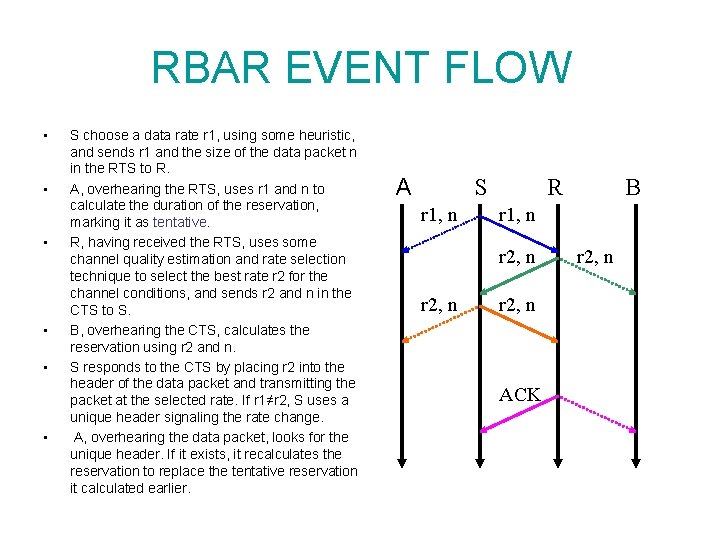
RBAR EVENT FLOW • • • S choose a data rate r 1, using some heuristic, and sends r 1 and the size of the data packet n in the RTS to R. A, overhearing the RTS, uses r 1 and n to calculate the duration of the reservation, marking it as tentative. R, having received the RTS, uses some channel quality estimation and rate selection technique to select the best rate r 2 for the channel conditions, and sends r 2 and n in the CTS to S. B, overhearing the CTS, calculates the reservation using r 2 and n. S responds to the CTS by placing r 2 into the header of the data packet and transmitting the packet at the selected rate. If r 1≠r 2, S uses a unique header signaling the rate change. A, overhearing the data packet, looks for the unique header. If it exists, it recalculates the reservation to replace the tentative reservation it calculated earlier. A S r 1, n R r 1, n r 2, n B r 2, n ACK r 2, n
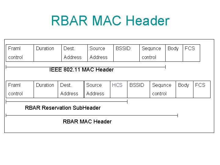
RBAR MAC Header Framl Duration control Dest. Source Address BSSID Sequnce Body FCS control IEEE 802. 11 MAC Header Framl control Duration Dest. Source Address RBAR Reservation Sub. Header RBAR MAC Header HCS BSSID Sequnce control Body FCS
RBAR RTS/CTS Implementation Frame Duration Rate & Dest. Source control Length Address FCS IEEE 802. 11 RTS RBAR RTS Frame Duration Rate & Dest. control Length Address FCS IEEE RBAR 802. 11 CTS § In RBAR, instead of carrying the duration of the reservation , the packets carry the modulation rate and the size of the data packet. §If there is rate mismatch between sender and receiver DRTS refer to as tentative reservation. §Final reservations are confirmed by the presence or absence of Reservation Sub. Header (RSH).
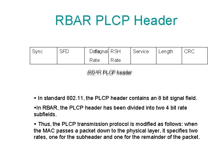
RBAR PLCP Header Sync SFD Data Signal RSH Rate Service Length CRC Rate RBAR PLCP header 802. 11 § In standard 802. 11, the PLCP header contains an 8 bit signal field. §In RBAR, the PLCP header has been divided into two 4 bit rate subfields. § Thus, the PLCP transmission protocol is modified as follows: when the MAC passes a packet down to the physical layer, it specifies two rates, one for the subheader and one for the remainder of the packet.
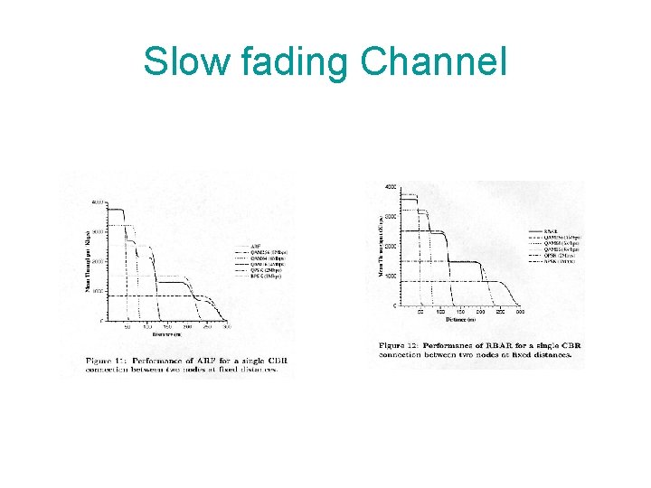
Slow fading Channel
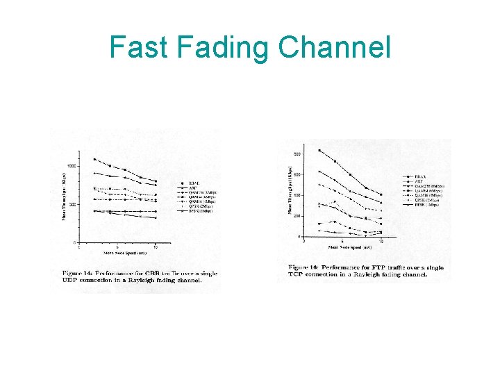
Fast Fading Channel
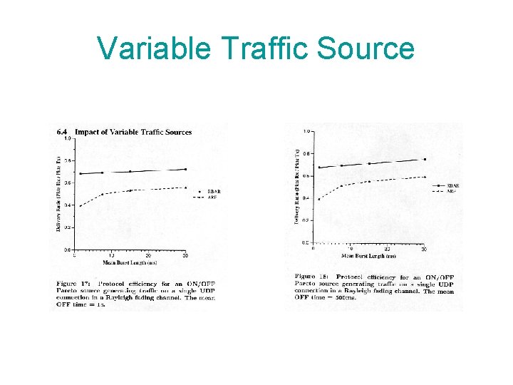
Variable Traffic Source
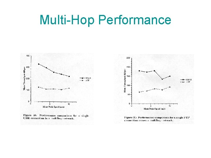
Multi-Hop Performance