Actuators Josep Amat and Alcia Casals Automatic Control


 Double effect pneumatic cylinders F = P* S")


")


 - Economic - Reliable - High operation speed - Operation at")
")

 Dv (cm 3) Q (l / min) Dl (cm)")


 Fix caudal")
 Fix caudal")
 Cylindrical pumps Variable caudal")

")


- Slides: 36
Actuators Josep Amat and Alícia Casals Automatic Control and Computer Engineering Department
User Environment External Sensors Programming and Supervision Sensors Interns Control Unit Actuators Mechanical Structure
ACTUATORS 1 – Pneumatic actuators Cylinders 2 – Hydraulic actuadors Cylinders Motors 3 – Electrical actuators Dc motors. Ac motors Steeper motors.
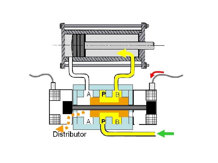
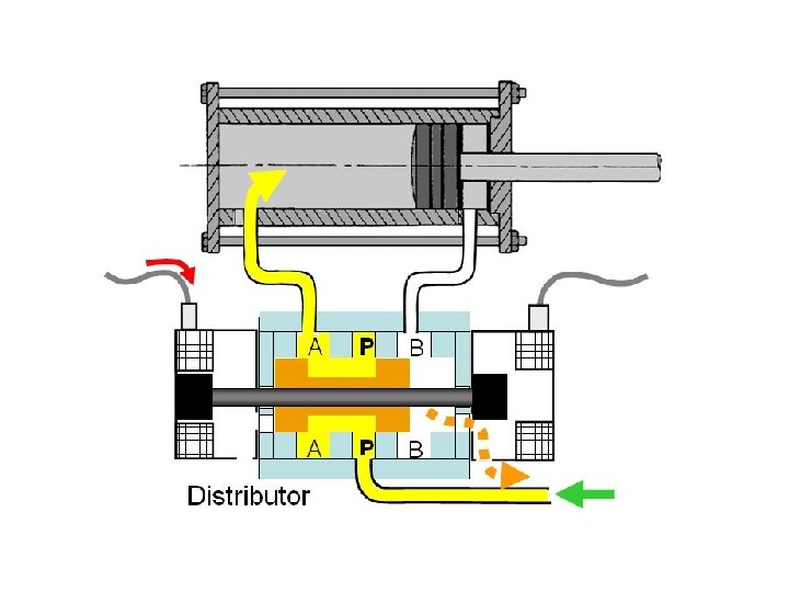
1 – Pneumatic actuators (cylinders) Double effect pneumatic cylinders F = P* S
V a v F = P* S F - Ff = M * a Ff = k * v 2 a = P * S - k * v 2 M Speed is not controllable. The cylinder maximum speed is achieved when friction forces (kv 2) equal those that produce the advancing movement (F = P. S), and a = 0.
V a v - The impact produced when reaching the end of the run is reduced using a shock absorber.
Electrical valve - Electrical valve: the hydraulic-electrical interface
Distributor
Double effect cylinders Single effect cylinders
Example of commercial pneumatic cylinders (Lateral guides to prevent axial rotation )
Oval pistons to prevent the rotation of the axis avoiding the need of auxiliary guides
l 2 l Classical cylinders drawbacks: a displacement of length l requires an additional length l.
Dl l Solutions to reduce the occupied space
Movement transmission Adjusting band Shock-absorber adjustment Cylinder’s sleeve Adjusting band Piston
Pneumatic actuators (cylinders) - Economic - Reliable - High operation speed - Operation at constant force - Resistant to overloads - No speed control - Poor position speed - Noisy operation
Example of pneumatic manipulator, and its mechanical states (End positions of all its cylinders)
ACTUATORS 1 – Pneumatic actuators Cylinders Motors 2 – Hydraulic actuadors Cylinders Motors 3 – Electrical actuators Dc motors. Ac motors Steeper motors.
2 – Hydraulic actuators (cylinders) Dv (cm 3) Q (l / min) Dl (cm) v (cm/seg. ) Energy source: oil pressurized between 20 and 300 bars. F = P* S If P ^^ F ∞ - Controllable position - Controllable speed
Control Electrical valve P Pressure Level M R B Pressure regulator Refrigeration Temperature Hydraulic circuit showing its essential elements
Atm. P The regulation of the cylinder retention force regulates the oil output producing a pressure drop. Schema of a pressure regulator
QA d Control P Electrical R valve QB Ideal characteristic R A P d B R
QA d Control P R A Electrical R valve P d B QB R
QA d Control P R A Electrical R valve P d B QB R
QA d Control P QB Electrical R valve Real characteristic R A P B d R
QA QB Control P Set point Qo R Sensor Servo valve Control QA QB A B Sensor d The use of a position sensor d makes the position servo control possible and thus hysteresis is minimized. The dead zone is minimized as well.
ACTUATORS 1 – Pneumatic actuators Cylinders Motors 2 – Hydraulic actuadors Cylinders Motors 3 – Electrical actuators Dc motors. Ac motors Steeper motors.
Hydraulic pumps and motors ( Kind of gears) Fix caudal
Hydraulic pumps and motors ( Kind of gears) Fix caudal
Hydraulic pumps ( Kind of radial pistons) Cylindrical pumps Variable caudal
e Caudal variation as a function of eccentricity e e
Hydraulic pumps and motors ( Kind of blades)
Hydraulic pumps or motors
Hydraulic actuators - Economic - Reliable - Able to support heavy loads - Resistant to overloads - Low working speed - Hydraulic group noisy in operation - Possible oil leakage