Activity Diagrams in Enterprise Architect Department of Software


- Slides: 31
Activity Diagrams in Enterprise Architect Department of Software
UML ─ An activity Diagrams Activity diagram is another important behavioral diagram in UML diagram to describe dynamic aspects of the system. Activity diagram is visually presents a series of actions or flow of control in a system similar to a flowchart or a data flow diagram. Activity diagrams are often used in business process modeling.
UML ─ An activity Diagrams Activity diagram is essentially an advanced version of flow chart that modeling the flow from one activity to another (diagrams describe the workflow behavior of a system). They can also describe the steps in a use case diagram (to expand on a use-case description) Activities modeled can be sequential and concurrent. In both cases an activity diagram will have a beginning (an initial state) and an end (a final state).
Activity Diagrams describe how activities are coordinated to provide a service – the service can be at di�erent levels of abstraction The process flows in the system are captured in the activity diagram Activity diagram illustrates the dynamic nature of a system by modeling the flow of control from activity to activity. activities and flows of data or decisions between activities Provides a very broad view of business processes
When to Use Activity Diagram 1 - Identify candidate use cases, through the examination of business workflows 2 - Identify pre- and post-conditions (the context) 3 - Model workflows between/within use cases 4 - Model complex workflows in operations on objects 5 -Model in detail complex activities in a high level activity Diagram
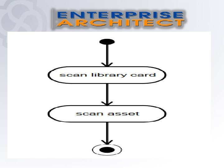
Activity Diagram Activity diagrams flow from top to bottom. The initial state is represented by a closed circle. It states the essential sequencing rules to follow. It is different from a flow chart in that it shows parallel processes, not just sequential processes Activity proceeds through a series of activity states until it reaches its final state, which is represented by a closed circle inside an open circle. Figure 1 is a simple activity diagram for the Check Out Asset use-case
Creating an Activity Diagram To create an activity diagram : Right click on model(Requirments or use case) add activity The tool box Contains : 1 - Elements(activity) 2 -activity relationship
Activity : is used to represent a set of action Action : A task to be performed
Decisions node A diamond represents a decision with alternate paths. When an activity requires a decision prior to moving on to the next activity, add a diamond between the two activities. The outgoing alternates should be labeled with a condition or guard expression. You can also label one of the paths "else. "
Merge Event A merge event brings together multiple flows that are not concurrent.
Synchronization A fork node: is used to split a single incoming flow into multiple concurrent flows. It is represented as a straight, thicker line in an activity diagram.
Synchronization A join node : joins multiple concurrent flows back into a single outgoing flow. A fork and join mode used together are often referred to as synchronization
Synchronization A join node : joins multiple concurrent flows back into a single outgoing flow. A fork and join mode used together are often referred to as synchronization
Initial State or Start Point A small filled circle followed by an arrow represents the initial action state or the start point for any activity diagram. .
Final State or End Point An arrow pointing to a filled circle nested inside another circle represents the final action state
Object node Is used to represent an object that is connected to a set of object flow
Exception handler Define the group of operation to carry out when exception occurs
Relationship 1 - control flow : show sequence of execution
Relationship 2 - object flow : refers to the creation and modification of objects by activities. An object flow arrow from an action to an object means that the action creates or influences the object. An object flow arrow from an object to an action indicates that the action state uses the object.
Relationship 3 - interrupt flow : use to connect activity with exception handler
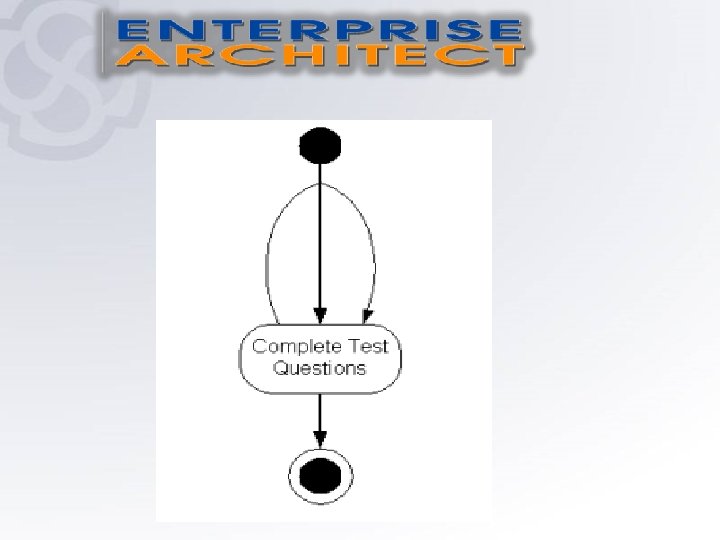
Iterations there are situations which will require certain actions to be performed more than once before an entire process can be completed. These situations can be described using iterations. An iteration is a step in a process which will repeat until a certain requirement is met. In the following example, consider a student working on a test. Until all the problems on the test are completed, the student will not be finished working on the test. The loop above the activity state of Completing Test Questions indicates that this step will be iterated until all the questions are answered.
Swimlane Guidelines * A swimlane is a way To group activities Performed by the Same actor on an Activity diagram or to group activities in a single thread • Swimlanes group related activities into one column. • For activity diagram using swimlanes, make sure the start point is placed in the top left corner of the first column
Swimlane Guidelines
In UML, guards are a statement written next to a decision diamond that must be true before moving next to the next activity. These are not essential, but are useful when a specific answer, such as "Yes
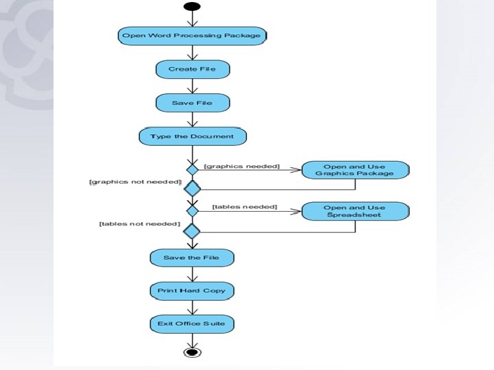
Example : creating document 1. Open the word processing package. 2. Create a file. 3. Save the file under a unique name within its directory. 4. Type the document. 5. If graphics are necessary, open the graphics package, create the graphics, and paste the graphics into the document. 6. If a spreadsheet is necessary, open the spreadsheet package, create the spreadsheet, and paste the spreadsheet into the document. 7. Save the file. 8. Print a hard copy of the document. 9. Exit the word processing package.
Example : processing an order Once the order is received the activities split into two parallel sets of activities. One side fills and sends the order while the other handles the billing. On the Fill Order side, the method of delivery is decided conditionally. Depending on the condition either the Overnight Delivery activity or the Regular Delivery activity is performed. Finally the parallel activities combine to close the order.
processing an order