Active Microwave Remote Sensing RadarRadio Detection and Ranging


 is smaller than the foreslope (a")


- Slides: 24
Active Microwave Remote Sensing
Radar=Radio Detection and Ranging Radar system components
Radar: How it Works • A directed beam of microwave pulses are transmitted from an antenna • The energy interacts with the terrain and is scattered • The backscattered microwave energy is measured by the antenna • Radar determines the direction and distance of the target from the instrument as well as the backscattering properties of the target
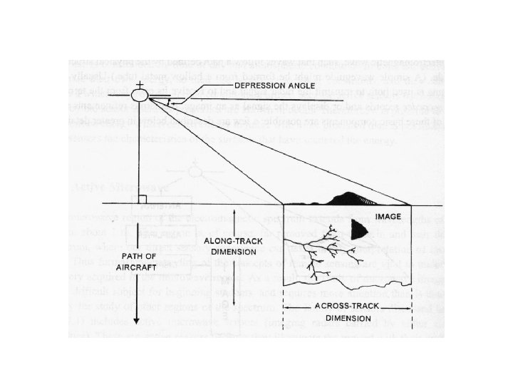
Radar Parameters • Azimuth Direction – direction of travel of aircraft or orbital track of satellite • Range angle – direction of radar illumination, usually perpendicular to azimuth direction • Depression angle – angle between horizontal plane and microwave pulse (near range depression angle > far range depression angle) • Incident angle – angle between microwave pulse and a line perpendicular to the local surface slope • Polarization – linearly polarized microwave energy emitted/received by the sensor (HH, VV, HV, VH)
Radar Nomenclature • Nadir • azimuth flight direction • look direction • range (near and far) • depression angle ( ) • incidence angle ( ) • altitude above-ground-level, H • polarization
Slant Range vs. Ground Range
Radar Pulse Length
Synthetic Aperture Radar • Antenna “length” is increased synthetically by building up a history of backscattered signals from the landscape along the track of the sensor • Implemented by keeping track of the Doppler shift of the reflected signal (frequency of the transmitted signal is known)
Layover occurs when the incidence angle ( ) is smaller than the foreslope (a + ) i. e. , < a+. This distortion cannot be corrected!
Radar Shadowing Radar shadowing can be useful for interpreting geomorphological features
Radar Backscatter Power received = Power per unit area at target x x Effective scattering area of the target Spreading loss of reradiated signal Effective receiving area of antenna x
Radar Backscatter Coefficient The efficiency the terrain to reflect the radar pulse is termed the “radar cross-section”, The radar cross-section per unit area, (A) is called the “radar backscatter coefficient” ( ˚) and is computed as : The radar backscatter coefficient determines the percentage of electro- magnetic energy reflected back to the radar from within a radar pixel This is similar to the reflectance in optical remote sensing
Radar Backscattering
Radar Backscattering Depends on the properties of the target: – roughness – dielectric constant Depends on characteristics of the radar: – depression angle – frequency/wavelength – polarization
Rayleigh Criterion for Roughness • A surface is considered smooth at or below a height, h, if: [ cm ] h = the vertical relief (average height of surface irregularities) = the radar wavelength (measured in cm) g = the depression angle
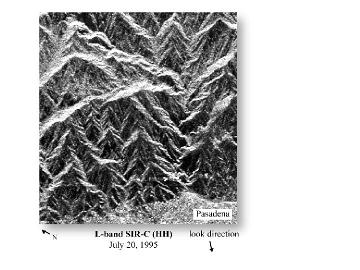
Surface Roughness in RADAR Imagery
Nile River Sudan Space Shuttle Color. Infrared Photograph SIR-C Color Composite: • Red = C-band HV • Green = L-band HV • Blue = L-band HH C-band, = 6 cm L-band, = 24 cm
Radar and the Dielectric Constant • Dielectric constant depends on the type of material as well as its moisture state – it is analogous to the refractive index of the material – it is primarily a function of moisture content – also depends on chemical properties such as salinity • Dielectric constant is the ratio of the capacitance of a material to that of a vacuum. Also known as the “relative permittivity”
Dielectric Constant dielectric constant of liquid water is 80; dry soil is 2 -4.
Radar frequency and backscatter • Depth of radar penetration through the vegetation canopy varies directly with
Types of Active Microwave Surface and Volume Scattering that Take Place in a Hypothetical Pine Forest Stand
Response of A Pine Forest Stand to X-, C- and L-band Microwave Energy