ACOUSTICAL DESIGN Sound absorption Acoustical absorption of furnishing

ACOUSTICAL DESIGN

Sound absorption Acoustical absorption of furnishing and curtain fabrics against walls readily absorb high frequencies but have limited absorption at low frequencies. � The further curtain fabrics are placed away from walls, the better the absorption is to include lower frequencies. The amount of sound energy absorbed depends on type of material, weight and pleating width. � Rock wool (fibreglass) has the highest absorption capacity, converting molecular air movement to heat (at molecular level). � Fibreglass consists of minute razor sharp fibres that are irritant and need to be contained within fabric. �

Sound absorption � Brick, stone, concrete, reflect all sound. Timber, gyprock, steel, reflect most high frequencies and a % low frequency is absorbed by the wall. The remaining low frequency energy that is not reflected or absorbed passes through the wall. Nothing can be done about sound that passes through a wall. Bass frequencies are the most difficult to absorb. � The 1/4 wave-length rule. Acoustical absorbent material must be placed away from walls and ceiling at a distance of 1/4 wavelength of the lowest frequency to be absorbed. This will include all higher frequencies if the absorbent material is soft furnishing (the ceiling should also be included). Understandably this will slightly reduce the physical size of the room. Acoustically the room will sound and feel LARGER. Also an acoustic absorbent environment is relaxing and calming.
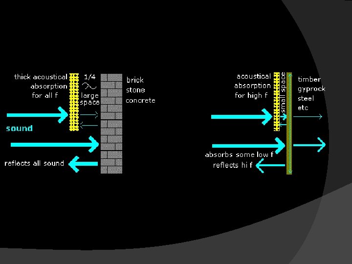
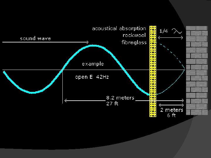

Bass trap refers to distance the absorbent material is from a wall to include absorbing bass frequencies. � Lowest frequency absorbed is governed by the material being at a distance of 1/4 wavelength from a wall. � Recording studios can have fabric up to 6 ft / 2 meters from walls. At 1/4 wavelength the molecular air movement is maximum, and is converted to heat by the absorbent material. The remaining sound that gets through the absorbent material is reflected back from the wall and again absorbed by the absorbent material. �

Standing Waves are bass frequencies reflected back from walls and ceiling. � The reflected bass interferes with the new incoming bass frequencies, causing cancellations at different points throughout the room. Each bass note will behave differently and the cancelled points will be in different positions. � Moving speakers or listening position does not solve the problem. The only solution is to insure that the room is 100% absorbent at all bass frequencies. �

Panel Absorbers consist of large sheets of plywood formed into complex architectural shapes. The panels can break up standing waves, deflect high frequencies and resonate to absorb bass energy. The formulas governing their behaviour are complex and the outcome is unpredictable and unknown until constructed. � require time consuming trial and error modifications to get them to work as predicted. �
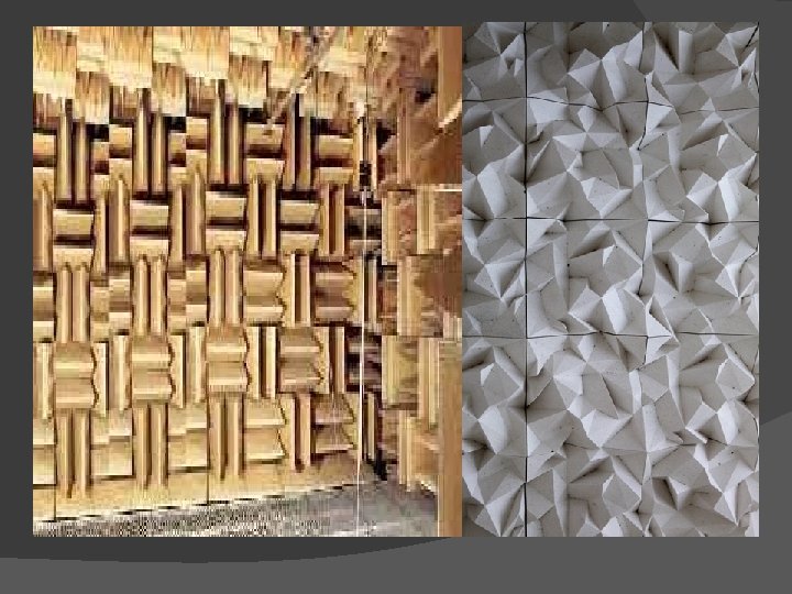

Anechoic chamber � is 100% absorbant at all frequencies. No sound can enter or escape from the room and is 100% silent. The closest we can experience this is in an open field, forest or desert on a perfectly still night. Simply described as free field. � No sound is reflected or returned.

Recording studio control rooms � have walls and ceiling slope outward and upward, away from the speakers and screen. Absolutely no sound should reflect from the rear wall. For amplified performance including cinema's, all walls and ceiling, should be as close to 100% absorbent as possible at all frequencies (free field). Recording studio control rooms often have walls and ceiling slope

Echo and excessive reverberation � destroys intelligibility and enjoyment for the audience. � Absolutely no echo must be allowed to be reflected from the back wall to the stage. � The further away the back wall is from the stage performance, the more acoustically absorbent the room should become.

For live acoustic performance the stage walls and ceiling can have a small % of controlled acoustic reflection to enhance the performance. Only from the stage. Acoustic path lengths must be as short as practical. Long acoustic path lengths are echoes (churches) and cause difficulty for musicians to play in time.

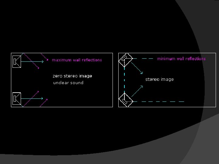
Sound system placement. Facing speakers directly forward adds excessive reflection from walls, and further reduces intelligibility. The speaker system should be turned inward to improve directivity, and minimise wall reflection. The angle that speakers could be turned inward can only be approximated by academic calculation. The most suited angle has to be found by trial and error. Wherever possible mixing should be from the centre, in stereo, where sound from left and right speakers intersects

Sound Weighting A Weighting sound measurement is non-linear and scaled in reference to our subjective hearing at low level. A weighting is used for noise measurement of office, work-place, and external traffic environment. A weighting is not appropriate for music and entertainment venues. C Weighting sound measurement is flat and therefore the correct method of measurement for music and entertainment venues. At higher power (music) our hearing tends to be even at all frequencies especially bass.

Building noise specifications are referenced to A Weighting sound measurement, and often limited to frequencies within voice range (250, 500, 1000 and 2000 Hz). Many architects have failed to fully understand the difference between A and C weighting specifications when designing entertainment venues. Bass energy is the most difficult to control, and the least understood, and therefore the largest problem in litigation issues of noise pollution.

Stopping sound The only way to stop all sound from entering or escaping a room is to construct double brick walls, double sealed ceilings, double sealed doors etc. This is approached from theory of 2 rooms, one within the other with an air gap in between. This is justified by recording, radio and TV studios, but is not economical practical for most homes and venues. The closer to achieving this the better with double-glazed windows, solid timber doors, sealing air gaps, multiple baffled air conditioning etc.

attenuation Reduction of signal strength during transmission. Attenuation is the opposite of amplification, and is normal when a signal is sent from one point to another. If the signal attenuates too much, it becomes unintelligible -d. B of reducing sound getting through a building material. Increasing the thickness of a building material x 2 increases attenuation by approx -6 d. B. Building materials are specified with Sound Transmission Class (STC) and Noise Reduction Coefficient (NRC). Education of STC and NRC is available on many building material suppliers web sites, including building construction details. STC and NRC only refer to isolation in speech frequencies (250, 500, 1000 and 2000 Hz) and provide no information of a materials ability to reduce low frequency noise, eg. bass in music etc.

reduce some sound getting through walls Absorbing sound within a room is essential. internal absorption has only limited ability to reduce sound that passes through walls. Absorbing sound that has been created inside the room limits reverberation therefore reducing overall sound energy. Absorbing the majority of sound before it strikes the first wall, reduces sound reflected to other walls

Material 125 Hz absorption approx 500 Hz 4 K Hz Brick or concrete 0. 01 0. 02 Plasterboard wall 0. 3 0. 06 0. 04 Plywood wall 0. 2 0. 1 Curtains heavy pleated 0. 15 0. 6 Curtains flat 0. 05 0. 2 0. 35 Fibreglass board 25 mm. 1 in 0. 06 0. 98 Fibreglass board 100 mm. 4 in 0. 99 Carpet 0. 01 0. 4

The table shows approx absorption of a material as a ratio. It can be seen that a plywood wall absorbs bass but reflects hi frequencies. Plywood and many other low weight building materials can act as low frequency resonant absorbers as described above in Panel absorbers. Increasing the thickness of a building material x 2 increases attenuation by approx -6 d. B.

Reverberation is the persistence of sound in a particular space after the original sound is produced. [1] is created when a sound is produced in an enclosed space causing a large number of echoes to build up and then slowly decay as the sound is absorbed by the walls and air. [2] This is most noticeable when the sound source stops but the reflections continue, decreasing in amplitude, until they can no longer be heard. The length of this sound decay, or reverberation time, receives special consideration in the architectural design of large chambers, which need to have specific reverberation times to achieve optimum performance for their intended activity. [3] In comparison to a distinct echo that is 50 to 100 ms after the initial sound, reverberation is many thousands of echoes that arrive in very quick succession (. 01 – 1 ms between echoes). As time passes, the volume of the many echoes is reduced until the echoes cannot be heard at all.

Subjective hearing experience Calculations for designing rooms with the appropriate acoustical absorption must include the subjective loudness of how we hear sound. Our ears expand when it is quite to hear detail and contract when loud. Many architects make errors by not including calculations for the subjective hearing experience of loudness variation and loss of intelligibility and annoyance caused by echo and reverberation. The result is that most entertainment venues, work environments and homes have less acoustical absorption than required, or at worst, no acoustical absorption at all. Repeat. A room that is larger requires more absorbent material with a higher absorbent coef.
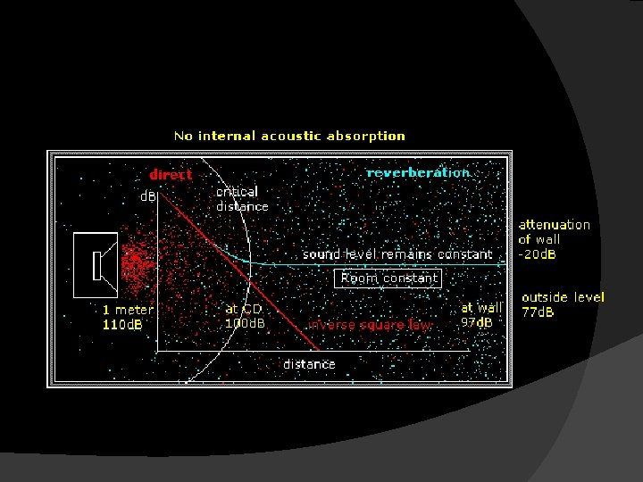

The drawings above and below are simplified to give a basic understanding of the principles described. No matter what calculations of room acoustics are being looked at, always keep the knowing of 'Critical Distance' as priority. The outcome objective is for the Critical Distance to be as far as possible from the sound source at all frequencies.

The more reverberant the room is, the closer the Critical Distance. The more absorbent the room is, the further the Critical Distance.

Architectural Acoustics

Acoustics is the science of noise control within buildings Basic objectives of acoustical control: 1. The control of all undesired sounds (HVAC, outdoor sources, etc. ) 2. The control of desired sounds so that it is appropriately loud and properly distributed without echo or distortion)
")
The control of all undesired sounds 1. Noise Barriers (wall, screen, building, etc. ) 2. Building Partition Design (drywall, brick/ concrete blocks, etc. ) 3. Building Floor and Ceiling Design (isolation performance of the construction-weight of floor system and ceiling, sound absorption in cavity, use of carpets, etc. ) 4. Exterior Envelope Design (exterior walls and windowsglass thickness, airspace thickness, etc. ) 5. HVAC Noise Control (silencers-lined ducts, exhaust silencers, etc. )

The control of desired sounds 1. Outdoor Sound Propagation 2. Amphitheater (environmental noise level, activity noise from surrounding area, performers, hearing/ viewing of audiences, amplification system, etc) 3. Listening Environment 4. Performing Environment 5. Reverberation

Architectural Acoustics 1. Room size, shaping, and proportion to optimize reverberant sound levels and room modal response 2. Specify interior finishes and room shaping to optimize reverberant sound levels and reflected energy patterns 3. Computer modeling of performance, critical listening, and other public gathering spaces where architectural acoustics are important 4. Control of reverberant sound to provide speech clarity and to support warmth and reverberance in musical performances 5. Evaluate room adjacencies to group compatible uses together or to design for sound control between incompatible uses 6. Design of exterior wall, roof, and window constructions and interior wall, floor, and ceiling constructions for sound isolation to prevent unwanted sound intrusion

Building skin envelope • noise transmission from building exterior envelope to interior and vice versa. • The main noise paths are roofs, eaves, walls, windows, door and penetrations. • Sufficient control ensures space functionality and is often required based on building use and local municipal codes. [

Inter-space noise control • The science of limiting and/or controlling noise transmission from one building space to another to ensure space functionality and speech privacy. • The typical sound paths are ceilings, room partitions, acoustic ceiling panels (such as wood dropped ceiling panels), doors, windows, flanking, ducting and other penetrations. • Technical solutions depend on the source of the noise and the path of acoustic transmission, for example noise by steps or noise by (air, water) flow vibrations. An example would be providing suitable party wall design in an apartment complex to minimise the mutual disturbance due to noise by residents in adjacent apartments.

The Sydney Opera House

Babri Masjid acoustic and cooling system “A whisper from the Babri Masjid Mihrab could be heard clearly at the other end, 200 feet [60 m] away and through the length and breadth of the central court” according to Graham Pickford, architect to Lord William Bentinck (1828– 1833). The mosque’s acoustics were mentioned by him in his book ‘Historic Structures of Oudhe’ where he says “for a 16 th century building the deployment and projection of voice from the pulpit is considerably advanced, the unique deployment of sound in this structure will astonish the visitor”. Modern architects have attributed this intriguing acoustic feature to a large recess in the wall of the Mihrab and several recesses in the surrounding walls which functioned as resonators; this design helped everyone to hear the speaker at the Mihrab. The sandstone used in building the Babri Mosque also had resonant qualities which contributed to the unique acoustics.
- Slides: 36