AbsorptionStripping Gasliquid separation processes Ch 10 COUNTERCURRENT MULTISTAGE
")
Absorption/Stripping Gas-liquid separation processes (Ch. 10)
 Distillation(Ch. 11) A Cooling")
COUNTER-CURRENT MULTISTAGE CONTACT OF GAS AND LIQUID Absorption (Ch. 10) Distillation(Ch. 11) A Cooling (condenser) A Cleaned Gas B Stripping (Ch. 10) Absorbent C Polluted feed liquid C+A B+A A B Feed A+B A A A B B Heat (reboiler) • • • Polluted feed gas B+A B (heavy) Two key components (A+B) One feed (normally) Two pure products Two sections Heating and cooling Boiling mixture C+A Stripping gas B Cleaned Liquid C • Three components • • Inert gas B (e. g. , air) Inert liquid C (e. g. , water) Solute A (e. g. , CO 2) goes from gas -> liquid Two feeds One pure product (at most) One section Non-boiling mixture • so p and T can be set independently; see Exercise Stripping: Reverse of absorption. Solute A goes from liquid -> gas

«VANNVASK» 4 identical absorption columns using pure water to absorb CO 2 from N 2/H 2 in ammonia plant. The only one in the world , as far as I know Originally, the CO 2 was used to make urea but now the CO 2 is the main supply of «brus» in Norway and Sweden. Designed about 1963 by Ingulf Skogestad, Norsk Hydro Engineering Office, Oslo. Built at Herøya (Porsgrunn) about 1967 (Norsk Hydro ammonia plant NII, now Yara) Sigurd Skogestad and Jan-Fredrik Arnulf (2013)

EXAM, Dec. 2016 Pure water from lake, 2000 m 3/h 0 Water recycle, 6000 m 3/h 10 Gas to ammonia 2 Plant 0, 3% CO 2 Pump 3 9 Abs. Tower CO 2 product (4 towers, Each D=3. 3 m h=35 m 77 trays) Air with CO 2 6 5 24 bar 10 C Flash 5. 5 bar 10 C 1. 1 bar 10 C 7 Turbine 4 1 Blower 0. 39% CO 2 Synthesis gas, 6700 kmol/h 17% CO 2, 35 C Air 8 Water to sea 220 000 Nm 3/h Revidert Si. S. 24. jan. 2017

Remove water from natural gas
 Partial A=CO 2 B=air")
Example: CO 2 capture from coal power plant (A=CO 2) Partial A=CO 2 B=air C=water/amine A=CO 2 B=steam (generated by reboiler) C=water/amine
. Find N –")
Absorption/stripping • Two solution approaches 1. Equilibrium-stage model (Ch. 10. 3). Find N – Similar to distillation – (A) Graphical: Mc. Cabe-Thiele (any VLE) – (B) Analytical: Kremser (VLE: Assume dilute solution. 1) Henry’s law, y = mx, +2) assume L/V constant) 2. Mass transfer model, (Ch. 10. 4+10. 6). – Find A=a. Sz (A=interfacial area) – Similar to heat transfer in heat exchanger • (A) Graphical: Must combine with integration • (B) Analytical (Henry’s law): Log-mean driving, (y-y*)LM
 for absorption/stripping • Equilibrium line usually straight line because of")
Graphical method (Mc. Cabe-Thiele) for absorption/stripping • Equilibrium line usually straight line because of dilute solution • Operating line goes through end points – These point are not on the diagonal* – Usually straight operating line because of dilute mixture • *Note: For distillation the operating lines go through (x. D, x. D) and (x. B, x. B), which are on the diagonal. – Reason: Reflux/boilup generates “feed stream” with same composition as product.
![Flows [mol/s] Flows generally vary through the column • L = L’/(1 -x) •](http://slidetodoc.com/presentation_image_h2/b6b21acb702a719231cf45de8adf8625/image-9.jpg "Flows [mol/s] Flows generally vary through the column • L = L’/(1 -x) •")
Flows [mol/s] Flows generally vary through the column • L = L’/(1 -x) • V = V’/(1 -y) x, y = mole fractions of component being transferred (A) L’ = inert liquid molar flow (C) V’ = inert vapor molar flow (B) For dilute mixtures we can assume (1 -x)=1 and (1 -y)=1 so L and V are constant through the column.

m=2. 53, L/V=3 L=90 kmol/h, V=30 kmol/h

From last time:
: Bottom end (x 0, y 1): Top end m=2. 53,")
(x. N, y. N+1): Bottom end (x 0, y 1): Top end m=2. 53, L/V=3 L=90 kmol/h, V=30 kmol/h Solution: Need N=5. 2 (approx. )
 in bottom where vapor")
Minimum flows Absorption: Lmin Stripping: Vmin • Absorption: Pinch (equilibrium) in bottom where vapor feed enters • Stripping: Pinch (equilibrium) in top where liquid feed enters • Corresponds to N=1

Lmin: Back to example Operating line with Lmin x’N = x*N+1 = y. N+1/m = 0. 01/2. 53 = 0. 004 From figure: Lmin/V = (y. N+1 – y 1)/(x*N+1 -x 0) = (0. 01 -0. 001)/(0. 004 -0)= 2. 277 So: Lmin = 30*2. 277 = 68. 3 kmol/h * = in equlibrium with the other phase Example: x*N+1 is (imaginary) liquid composition in equlibrium with y*N+1
 V y. N+1")
Lmin: «Alternative» derivation • From overall mass balance (assuming constant flows) V y. N+1 + L x 0 = V y 1 + L x. N • Assume equlibrium in bottom (pinch) x. N = x*N+1 = y. N+1/m = 0. 0040 • Get min. reflux. Lmin/V = (y. N+1 – y 1)/(x*N+1 -x 0)
 • Example: 1 stage")
Minimum stages, Nmin • No such thing for absorption/stripping (Nmin=0) • Example: 1 stage is OK if we increase flows enough – Absorption: increase L enough – Stripping: increase V enough

N=1: Back to example Operating line with N=1 x*1 = y 1/m = 0. 001/2. 53 = 0. 0004 From figure: L/V = (y. N+1 – y 1)/(x*1 -x 0) = (0. 01 -0. 001)/(0. 0004 -0)= 22. 77 So: L = 30*22. 77 = 683 kmol/h
 and L/V")
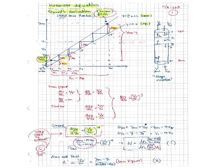
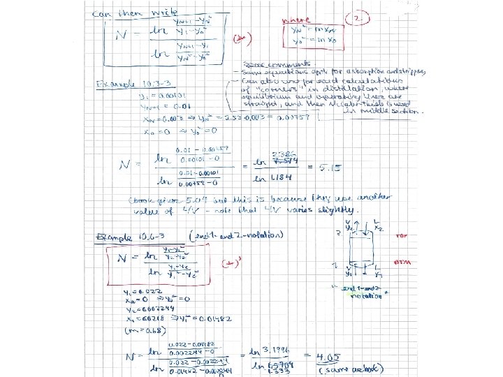
Kremser equations • Analytical solution for case with straight equilibrium line (y=mx) and L/V constant (dilute mixtures) • A = (L/V)/m – absorption factor = ratio of slopes for operating and equilibrium lines – Absorption: want A large – Stripping: Want A small V L y*0 = mx 0 V L y*N = mx. N • = in equilibrium with other phase (could be imaginary composition, like y *0) (next page)

Minimum flows Example 1: A fun absorption problem • Dear Absorption and distillation experts: Can you solve this? This problem is based on a true story. My father, Ingulf Skogestad, got his degree as a chemical engineer at NTH in Trondheim in 1948. It was difficult to find good process jobs in Norway at that time, so his career got a boost when he during 1956 -61 worked at two ammonia plants that ICI operated in South Africa. • This is a story from Modderfontein near Johannesburg in 1959 where they had a problem of not reaching the gas spec. in an absorption tower. They build an identical tower no. 2 (in series) but still they could not reach the spec. My father found a solution that worked: He took the absorbent (liquid) from tower 2 and used it in tower 1 (and left tower 2 as a spare). This was at the time explained by the fact that there was too little liquid in tower 1 to get proper wetting of the packing, but I think it may have been a more fundamental mass balance problem. • To illustrate this I have made the following problem: A gas stream of 1 mol/s has 4 mol% of component A, and it should be reduced to 0. 1% in an absorption tower with use of 6 mol/s pure water. However, in spite of the tower being very tall, the fraction of A in the gas product is too high (about 1. 6% A). To reduce the concentration of A, an identical tower 2 is build, where the exit gas from tower 1 (with 1. 6% A) is treated with 6 mol/s pure water. However, one still is not able to reach the desired 0. 1% A. Data: Henry's law for component A: y = mx, where m = H/p = 10 (p is the column pressure, which is 1 bar). (a) Make a flowsheet for the two alternatives. (b) Can it be correct that one achieves 1. 6% A in tower 1? (c) What is the concentration of A in the gas leaving tower 2? (d) An engineer always finds a solution! In this case it is to use all the water (12 mol/s) in tower 1 (and leave tower 2 as a spare). Can you explain why this works, and find the exit gas concentration of A in this case.
 2. New design (Two towers in")
1. Original design: (One tower, 6 mol/s water) 2. New design (Two towers in series, total 12 mol/s water) Cleaned gas Desired: y 2 = 0. 001 (c) Actual: y 2=0. 0064 V’y’ 2 = V’y’ 1 – L’x’ 1) y’ 2=0. 0064 Cleaned gas Desired: y 2 = 0. 001 Actual: y 2=0. 016 3. Final design** L=6 mol/s x 2=0 (pure water) (b) Vy 2 = Vy 1 – Lx 1) y 2=0. 016 L=6 mol/s x 2=0 (One tower, 12 mol/s water) Cleaned gas L=12 mol/s Desired: y 2 = 0. 0012 x 2=0 (pure water) Actual: y 2<0. 001 (d) Not enough data to find exact y (need N or similar) end 2 end 1 Polluted gas V=1 mol/s y 1 = 0. 04 Btm: Close to equilibrium (pinch): x 1=x 1*=y 1/m=0. 04/10=0. 004. Polluted gas (L/V)min= (0. 04 -0. 001)/0. 004=9. 75 V=1 mol/s y 1 = 0. 04 Pinch: x'1=x’ 1*=0. 016/10=0. 0016 y’ 1=y 2=0. 016 Polluted gas V=1 mol/s y 1 = 0. 04 **If liquid load too large: Can split the gas and have two towers in parallel. Each with half L and V.
 PROBLEM 2. STRIPPING. Water from an")
Minimum flows Example 2 (Problem 2, exam 2004) PROBLEM 2. STRIPPING. Water from an oil installation contains 8 mg benzene per liter water. It should be reduced to 0. 4 mg benzene per liter by stripping with air at 2 atm. (a) Find the minimum amount of air (m 3 air/m 3 water). How many equilibrium stages does this require? SOLUTION. General approach: (i) Convert everything to molar + (Find product streams from mass balance) (ii) Minimum flows: This is with infinite no. of stages and it occurs when we have “pinch” For absorption/stripping: “Pinch” at one end -> product and feed in equilibrium! eq. V (air) Assume: L and V constant through column (dilute-> x and y small) + Assume T=300 K (not given!) + assume ideal gas L (water+ benzene) (i) Conversion to molar: “ 8 mg benzene per liter water”. nb = 8 mg benzene = 8 e-3 g / 78 g/mol = 1. 026 e-4 mol nw= 1 liter water = 1 kg water = 1000 g/ 18 g/mol = 55. 55 mol x 0 = nb/(nb+nx) = 1. 846 e-6 = 1. 846 ppm Similar: x. N = x 0*0. 4/8 = 0. 05 x 0 = 9. 231 e-8 = 0. 092 ppm Infinite number of stages: y 1 and x 0 are in equilibrium -> y 1 = (H/p) x 0 = (383. 5 bar/2 bar)*1. 846 e-6 = 3. 54 e-4 = 354 ppm (ii) Can now find minimum air flow from overall material balance: Lx 0 + Vy. N+1 = Lx. N + Vy 1 Or L(x 0 -x. N) = V (y 1 -y. N+1) Or V = L(x 0 -x. N)/(y 1 -y. N+1) = L (1. 846 -0. 092)/(354 -0) = 0. 00495 L [mol/s] Water: Given L = 1 m 3 = 1000 kg = 55. 55 kmol Air: Get V = 0. 00495 L = 0. 275 kmol = 275 (RT/p) [m 3] = 275*8. 31*300/2 e 5 [m 3] = 3. 43 m 3 (gas)
 • See lecture no. 3 from Jana • Mass transfer based")
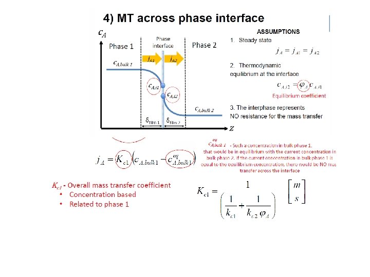
Diffusion (Two-film theory) • See lecture no. 3 from Jana • Mass transfer based on bulk compositiums NA = Ky (y-y*) = Kx (x-x*) [mol/s m 2] Ky = m K x • Assume dilute mixture, so that drift of film can be neglected: Ky = K’y • To find overall mass transfer coefficient: Add resistances: 1/Ky = 1/ky + m/kx

Mass transfer approach • • • Two-film mass transfer model Bulk phases not in equilibrium Dilute mixtures (1 -x ¼ 1) – – Henry’s law: y*i = m xi Constant (molar) flows: L ¼ L’ (inert) • Mass transfer (Non-equilibrium) model • Get differential equation (dn. A/dz=…) instead of difference equations: • • • Mass transfer: Mass balance over dz: Combine: – Packing height (integrate): NA = Ky (y – y*) [mol A/s, m 2] dn. A = Vdy = NA d. A, where d. A = a. Sdz dz = V dy / Ky a S (y-y*) HOG [m] = hight of transfer unit – – NOG [-] = number of transfer units Integrate expression for NOG numerically (computer) or graphically (exercise) For dilute mixtures (Analytical Log-mean approximation): NOG =

Proof of expression for NOG • y-y* is the difference between the operating and equilibrium lines and for dilute mixtures it changes linearly with x (and with y) so write 1: y-y* = ky + b • Book (p. 671) says that this «can be integrated» to get the desired result, but skips the details. Here is a proof. • Integral of 1/(y-y*)=1/(ky+b) is ln(ky+b)/k = ln(y-y*)/k • Integrate this from end 2 to end 1, get • NOG = ln [(y-y*)1/(y-y*)2] * 1/k Now the «trick» comes. Note that k is the slope of (y-y*) as a function of y. So using the two ends 1 and 2, we have QED k = [(y-y*)1 -(y-y*)2] / [y 1 – y 2] 1. Comment: By writing y=(L/V)x+a and y*=mx, we have that y-y*=(L/V - m)x + a, and by using x = (y-a)/(L/V) we find that k = (L/V – m)/(L/V) = 1 – 1/A where A=(L/V)/m

Absorption/stripping in packed towers. Useful log-mean formula for dilute mixtures 2 z 1 y*=mx y

Multistage separation with given products: Minimum number of stages • There is no “minimum number of stages” in absorption/stripping • Can have N -> 0 if we have very large flow (of solvent or stripping gas). • Note: Purities of incoming streams (column ends) are fixed, and this limits product purities, independent of the number of stages. • Distillation is different: Here we “recycle” at the column ends and can achieve any product purity by increasing the number of stages. – Fenske: Nmin = ln. S/ln®
 • Absorption/stripping: minimum solvent/stripping gas")
Multistage separation with given products: Minimum flows (Lmin, Vmin) • Absorption/stripping: minimum solvent/stripping gas • Obtained with infinite large column (infinite no. of stages) • General: Occurs when we have “pinch” somewhere No change in composition between stages = Crossing of equilibrium and operating line = Compositions between stages in equilibrium • Absorption/stripping: usually occurs at column end -> one product is in equilibrium with its feed

10. 6 C Pressure drop and flooding in packed columns To find column diameter and pressure drop: 1. Obtain packing factor Fp (from Table) 2. Find flooding pressure drop 3. Find corresponding flooding gas velocity (using pressure drop correlation in Figure) – Typical: vflood is about 6. 6 ft/s = 2 m/s 4. Choose diameter such that gas velocity is about half of this – Typical: Design for v = 1 m/s 5. Find pressure drop in column (from pressure drop correlation in Figure)

Table 10. 6 -1. Packing factors Fp

• Pressure drop correlations

11. 5 F Flooding velocity and Diameter of tray towers To find column diameter and pressure drop: 1. Obtain tray factor Kv [ft/s] (from Figure) 2. Find entrainment gas velocity from eq. 11. 5 -14 (occurs just before flooding). Fair correlation: 3. 4. Choose diameter so that gas velocity is about v = 0. 7 vmax Pressure drop: Usually much larger than in packed columns, because of pressure drop for gas to pass through liquid on trays

6’’ = 6 inches = 18 cm

Summary: Absorption/Stripping • • • Single section Notation varies… Dilute mixtures: – – 1 -x ¼ 1 Henry’s law: pi = H xi • • – • Using pi = yi p gives yi = (H/p) x i = m xi Constant (molar) flows: L ¼ L’ (inert) Modelling. Two approaches 1. Equilibrium stage (as for distillation, but simpler) • • (A) Graphical: Mc. Cabe Thiele for nonideal VLE (B) Analytical for dilute mixtures: Kremser formulas. A = (L/V)/m 2. Mass transfer (Non-equilibrium) models
 Differential model (Packed column) Equilibrium (between")
Summary countercurrent vapor-liquid separation Stage model (Tray column) Differential model (Packed column) Equilibrium (between liquid and vapor bulk phases) Eq. stage. (Most common model in practice!) Mc. Cabe-Thiele Dilute: Fenske, Kremser (Not possible with differential model*) (But one can use eq. stage + HETP!) Nonequilibrium (Not covered in this course) Non-equilibrium between bulk phases is used sometimes. May use two-film theory on stages Most common is two -film approach. Nondilute: Numerical integration Dilute mixtures: logmean formula. *Would give column with height=0
- Slides: 38