
AAE 17521 Chapter 1 Theory of Combustion PREPARED
AAE 17521 Chapter 1 Theory of Combustion PREPARED BY S. D. GANDHI
1. 1 Combustion in S. I. engines �Ignition Limits Ignition Limit corresponds approximately to that mixture ratio, at lean & rich ends of the scale, where the heat released by spark is no longer sufficient to initiate combustion in the neighbouring UN burnt mixture. The flame will propagate only if the temperature of the burnt gases exceeds approximately 12500 C in the case of hydrocarbon-air mixture. The lower & upper ignition limits of the mixture depend upon mixture ratio & flame temperature. The ignition limits are wider at increased temperature because of higher rates of reaction.
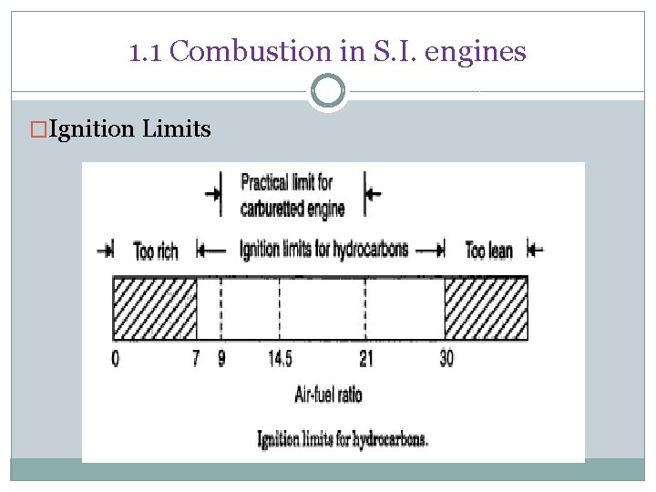
1. 1 Combustion in S. I. engines �Ignition Limits
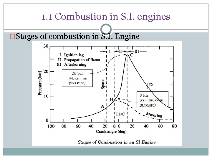
1. 1 Combustion in S. I. engines �Stages of combustion in S. I. Engine
1. 1 Combustion in S. I. engines �Stages of combustion in S. I. Engine Stage I: -Ignition Lag or Preparation Phase. �It is a chemical process which depends on-nature of fuel, temperature & pressure, proportion of exhaust gas, rate of burning and temperature . It is the growth and development of a semi propagating nucleus of flame. (At the moment of spark discharge, the temperature exceeds 10, 0000 c) � At the end of this stage, the first rise of pressure (on indicator diagram) can be detected. It is the point where the line of combustion departs from the compression line.
1. 1 Combustion in S. I. engines �Stages of combustion in S. I. Engine Stage II: - Propagation of flame �-It is a simple, pure and mechanical process. The starting point of the second stage is where first measurable rise of pressure can be seen on the indicator diagram. i. e. the point where the line of the combustion departs from the compression line. During second stage, the flame spreads throughout the combustion chamber. The second stage ends as maximum pressure (on indicator diagram) is reached.
1. 1 Combustion in S. I. engines �Stages of combustion in S. I. Engine Stage III after burning �End of second stage means completion of flame travel. But it does not result in complete heat release (burning of fuel). �Even after the passage of flame, some chemical adjustments continue throughout the expansion stroke- near the walls and behind the turbulent flame front. The rate of combustion reduces due to surface of the flame front becoming smaller and reduction in turbulence.
Effect of engine variables on Ignition Lag Ignition lag is a chemical process. The ignition lag in term of crank angle is 10 o to 20 o& in terms of second, 0. 0015 second. The duration of ignition lag depend on �Fuel- it is depend on chemical nature of fuel. The higher, the self ignition temp of fuel, the longer, the ignition lag �Mixture Ratio-The ignition lag is smallest for the mixture ratio which gives the maximum temperature this mixture ratio is some what richer than the stoichiometric ratio. �Initial pressure and temperature –increasing the intake temp, pressure, compression ratio and retarding spark, all reduce the ignition lag.
Effect of engine variables on Ignition Lag �Electrode gap- It affects establishment of the nucleus of flame. If the gap is too small, quenching of the flame nucleus may occur & rang of fuel –air ratio for the development of a flame nucleus is reduced. �Turbulence- measured in degree of crank-rotation the ignition lag increases almost linearly with engine speed. For this reason. It becomes necessary to advance the spark timing at higher speed. Excessive turbulence of the mixture in the area of the spark plug is harmful, since it increases the heat transfer from the combustion zone & leads to unstable development of the nucleus of flame. That is way the spark plug is usually arranged in a small recess in the wall of the combustion chamber.
Effect of engine variables on Flame Propagation �Fuel –Air ratio: - With hydrocarbon fuels the maximum flame velocities occur when mixture strength is 110% of stoichiometric. Lean mixtures release less thermal energy resulting in lower flame temperature & flame speed. Very rich mixtures have incomplete combustion (Some carbon only burns to CO & not to CO 2), which results in production of less thermal energy & hence flame speed is again low. �Compression ratio-A higher compression ratio increases the pressure & temperature of the working mixture & decrease the concentration of residual gases. High pressures & temperature of the compressed mixture also speed up the second phase of combustion. Total ignition angle is reduced. Maximum pressure are increased �Intake temp & pressure-increase in the intake temp & pr. Increase the flame speed.
Effect of engine variables on Flame Propagation �Engine load: -With increases in the engine load the cycle pressures increase. Hence the flame speed increases. �Turbulence: -The flame speed is very low in nonturbulent mixtures. A turbulent motion of the mixture intensifies the processes of heat transfer & mixing of the burned & unburned portions in the flame front (diffusion). These two factors cause the velocity of turbulent flame to increase practically in proportion to the turbulence velocity. However, excessive turbulence is also undesirable.
Effect of engine variables on Flame Propagation �Engine speed – the higher the engine speed the greater the turbulence inside the cylinder. For this reason the flame speed increases almost linearly with engine speed. The crank angle required for the flame propagation, which is the main phase of combustion, will remain almost constant at all speed. �Engine size- engine of similar design generally run at the same piston speed. This is achieved by smaller engine having larger RPM & larger engines having smaller RPM. Due to the same piston speed. The inlet velocity, the degree of turbulence & the flame speed are nearly same in similar engines regardless of the size. i. e. the number of crank degrees required for flame travel will be about the same irrespective of engine size, provided the engine are similar.
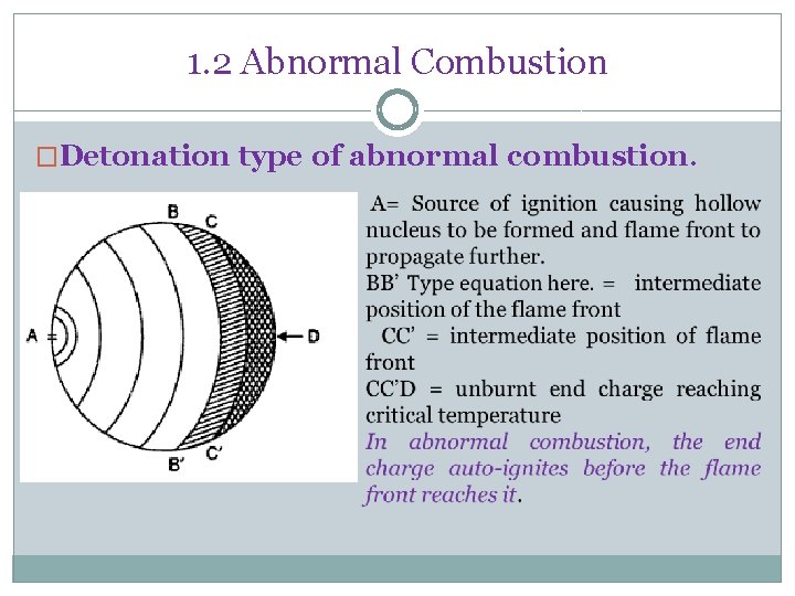
1. 2 Abnormal Combustion �Detonation type of abnormal combustion.
1. 2 Abnormal Combustion � Detonation type of abnormal combustion. � Figure shows combustion with detonation. The flame front has reached BB’ and the unburnt charge BB’D has reached the critical conditions for auto-ignition. In this case there is a possibility of detonation. If the flame front can proceed from BB’ to D and consume the unburnt charge in a normal manner, prior to completion of the Ignition delay period, there will be no detonation. � If, however, the flame front is able to proceed only as far as, say CC’, during the ignition delay period, then the remaining portion of the unburnt charge CC’D will autoignite and cause extreme pressure fluctuations from about 50 bar to 150 -200 bar.
Effects of detonation � Noise and vibration: vibration the presence of vibratory motion causes crankshaft vibrations and the engine runs rough. � Mechanical damage: damage the cylinder head and valves may be pitted, increased rate of wear may occur. � Carbon Deposits: Deposits detonation results in increased carbon deposits. � Increase in heat transfer: transfer occurs due to scouring away of protective layer of inactive stagnant gas on the cylinder walls due to pressure waves. � Decrease in power output and efficiency: due to increase in efficiency the rate of heat transfer the power output as well as efficiency of a detonating engine decreases. � Pre-ignition: Pre-ignition The increased rate of heat transfer to walls causes local overheating of spark plug, which ignites charge before the spark, thus causing Pre- ignition.
Control of detonation Methods of controlling detonation: By controlling following engine variables, detonation can be controlled. � Increasing engine rpm. � Retarding spark timing � Reducing pressure in inlet manifold by throttling. In supercharged engines reducing supercharging pressures reduces detonation. � Making the ratio too lean or too rich, preferably latter. � Water injection.
Control of detonation By design features, detonation can be reduced. � Use of low compression ratio. � Increasing turbulence � Relocating spark plugs or use of two or more spark plugs. � Suitable combustion chamber design to reduce flame length and to reduce temperature of end gas. � It can be eliminated by using High octane fuels, or by adding additives known as dopes to petrol.
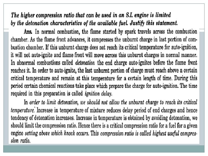
What is Ignition delay? How it affects the combustion process in S. I. Engine? � In abnormal combustion, called detonation, end charge auto-ignites before the flame front reaches it. To auto-ignite, the last unburnt charge must reach above critical temperature and remain at this temperature for certain length of time. This time required in the chemical preparation phase is called “Ignition Delay”. Delay � If ignition delay period is longer than the time required for the flame front to burn through the unburnt charge, there will be no detonation in S. I Engine. � Only when the critical temperature is reached and maintained, and the ignition delay is shorter than the time it takes for the flame front to burn through the unburnt charge, there will be detonation.
1. 2 Abnormal Combustion Pre-ignition � The increase in the rate of heat transfer to the walls may cause local overheating specially of the spark plug, which may reach a temperature high enough to ignite the charge before the passage of spark. This phenomenon is called Pre -ignition. � Pre-ignition may also be caused by overheated exhaust valves or glowing carbon deposits in the combustion chamber.
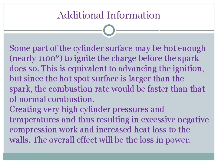
Additional Information Some part of the cylinder surface may be hot enough (nearly 1100°) to ignite the charge before the spark does so. This is equivalent to advancing the ignition, but since the hot spot surface is larger than the spark, the combustion rate would be faster than that of normal combustion. Creating very high cylinder pressures and temperatures and thus resulting in excessive negative compression work and increased heat loss to the walls. The overall effect will be the loss in power.
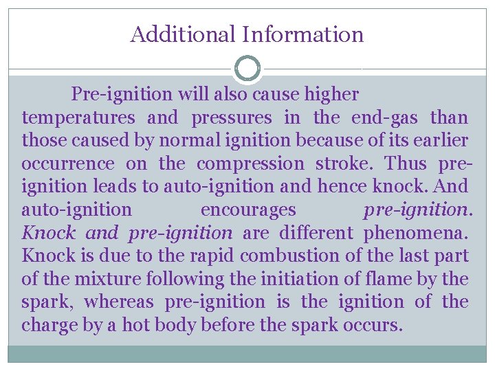
Additional Information Pre-ignition will also cause higher temperatures and pressures in the end-gas than those caused by normal ignition because of its earlier occurrence on the compression stroke. Thus preignition leads to auto-ignition and hence knock. And auto-ignition encourages pre-ignition. Knock and pre-ignition are different phenomena. Knock is due to the rapid combustion of the last part of the mixture following the initiation of flame by the spark, whereas pre-ignition is the ignition of the charge by a hot body before the spark occurs.
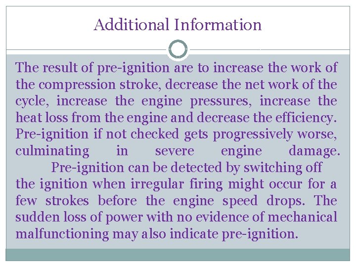
Additional Information The result of pre-ignition are to increase the work of the compression stroke, decrease the net work of the cycle, increase the engine pressures, increase the heat loss from the engine and decrease the efficiency. Pre-ignition if not checked gets progressively worse, culminating in severe engine damage. Pre-ignition can be detected by switching off the ignition when irregular firing might occur for a few strokes before the engine speed drops. The sudden loss of power with no evidence of mechanical malfunctioning may also indicate pre-ignition.
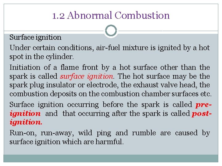
1. 2 Abnormal Combustion Surface ignition Under certain conditions, air-fuel mixture is ignited by a hot spot in the cylinder. Initiation of a flame front by a hot surface other than the spark is called surface ignition. The hot surface may be the spark plug insulator or electrode, the exhaust valve head, the combustion deposits on the combustion chamber surfaces etc. Surface ignition occurring before the spark is called preignition and that occurring after the spark is called postignition. Run-on, run-away, wild ping and rumble are caused by surface ignition which are harmful.
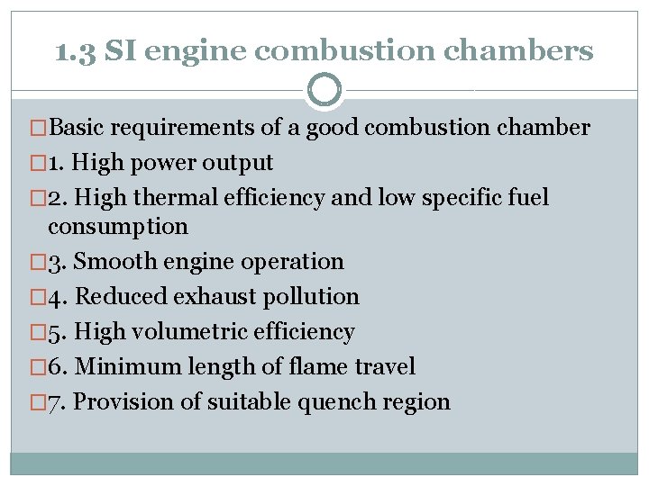
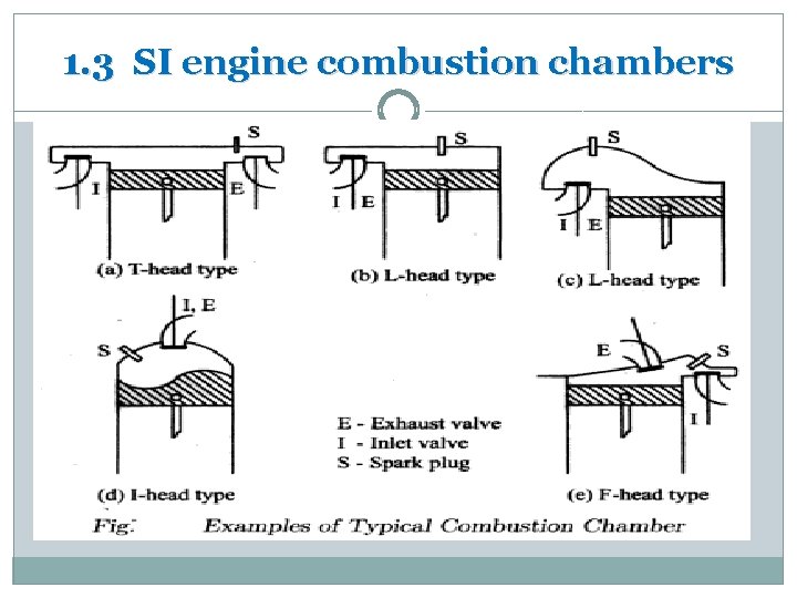
1. 3 SI engine combustion chambers �Basic requirements of a good combustion chamber � 1. High power output � 2. High thermal efficiency and low specific fuel consumption � 3. Smooth engine operation � 4. Reduced exhaust pollution � 5. High volumetric efficiency � 6. Minimum length of flame travel � 7. Provision of suitable quench region
1. 3 SI engine combustion chambers
1. 3 SI engine combustion chambers
1. 3 SI engine combustion chambers
1. 3 SI engine combustion chambers
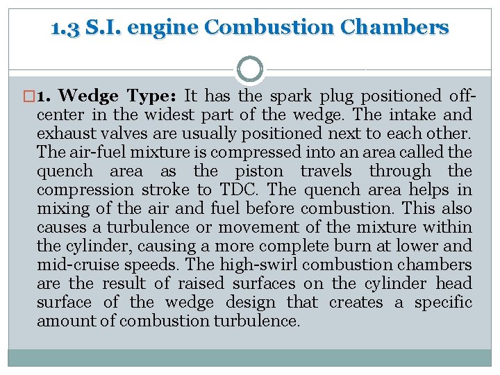
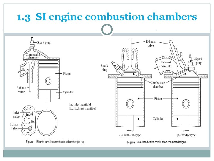
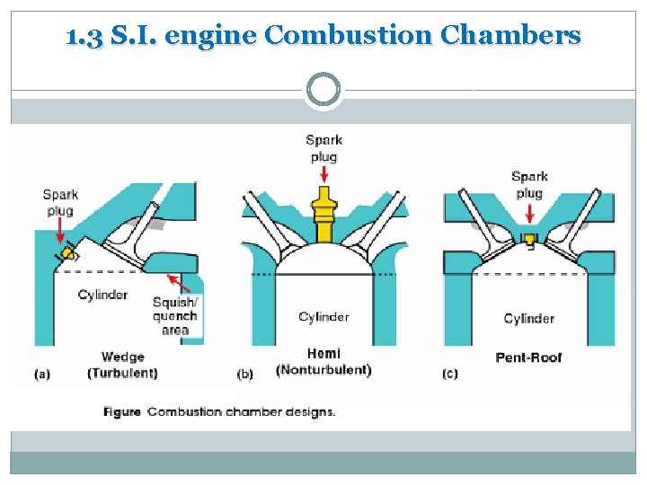
1. 3 S. I. engine Combustion Chambers � 1. Wedge Type: It has the spark plug positioned off- center in the widest part of the wedge. The intake and exhaust valves are usually positioned next to each other. The air-fuel mixture is compressed into an area called the quench area as the piston travels through the compression stroke to TDC. The quench area helps in mixing of the air and fuel before combustion. This also causes a turbulence or movement of the mixture within the cylinder, causing a more complete burn at lower and mid-cruise speeds. The high-swirl combustion chambers are the result of raised surfaces on the cylinder head surface of the wedge design that creates a specific amount of combustion turbulence.
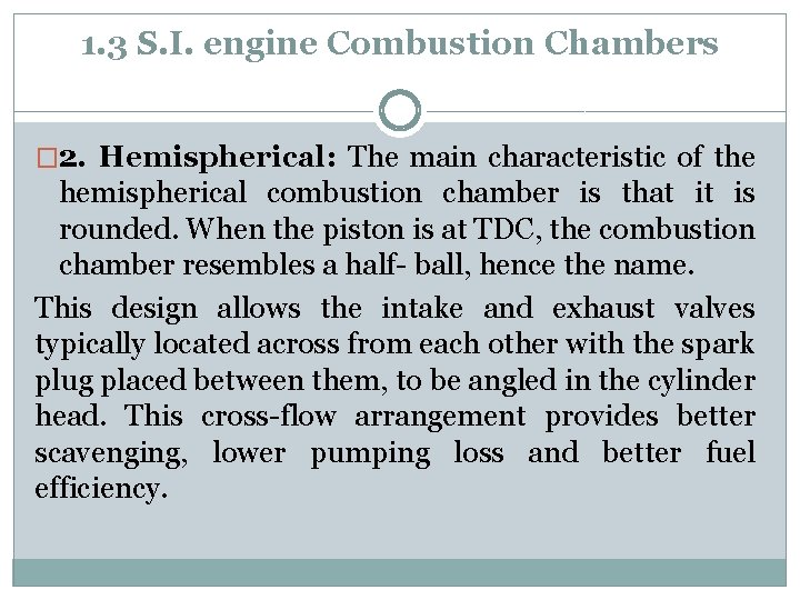
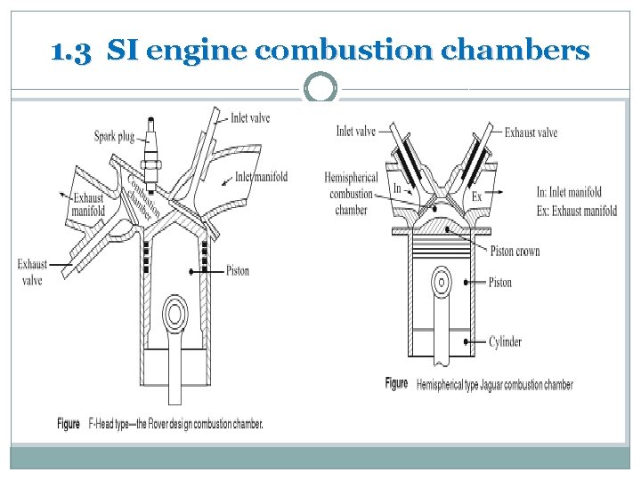
1. 3 S. I. engine Combustion Chambers � 2. Hemispherical: The main characteristic of the hemispherical combustion chamber is that it is rounded. When the piston is at TDC, the combustion chamber resembles a half- ball, hence the name. This design allows the intake and exhaust valves typically located across from each other with the spark plug placed between them, to be angled in the cylinder head. This cross-flow arrangement provides better scavenging, lower pumping loss and better fuel efficiency.
1. 3 S. I. engine Combustion Chambers
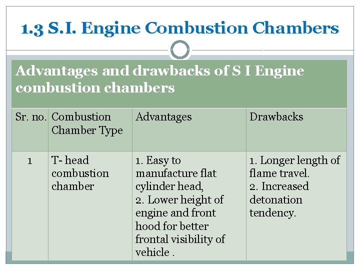
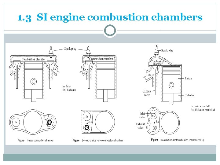
1. 3 S. I. Engine Combustion Chambers Advantages and drawbacks of S I Engine combustion chambers Sr. no. Combustion Advantages Chamber Type 1 T- head combustion chamber 1. Easy to manufacture flat cylinder head, 2. Lower height of engine and front hood for better frontal visibility of vehicle. Drawbacks 1. Longer length of flame travel. 2. Increased detonation tendency.
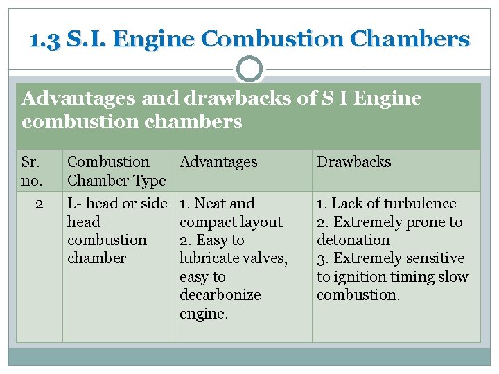
1. 3 S. I. Engine Combustion Chambers Advantages and drawbacks of S I Engine combustion chambers Sr. no. 2 Combustion Advantages Chamber Type Drawbacks L- head or side head combustion chamber 1. Lack of turbulence 2. Extremely prone to detonation 3. Extremely sensitive to ignition timing slow combustion. 1. Neat and compact layout 2. Easy to lubricate valves, easy to decarbonize engine.
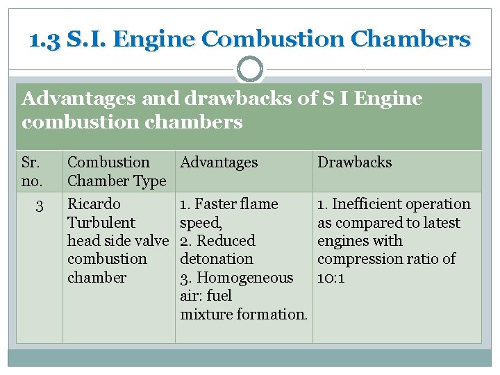
1. 3 S. I. Engine Combustion Chambers Advantages and drawbacks of S I Engine combustion chambers Sr. no. 3 Combustion Advantages Chamber Type Drawbacks Ricardo Turbulent head side valve combustion chamber 1. Inefficient operation as compared to latest engines with compression ratio of 10: 1 1. Faster flame speed, 2. Reduced detonation 3. Homogeneous air: fuel mixture formation.
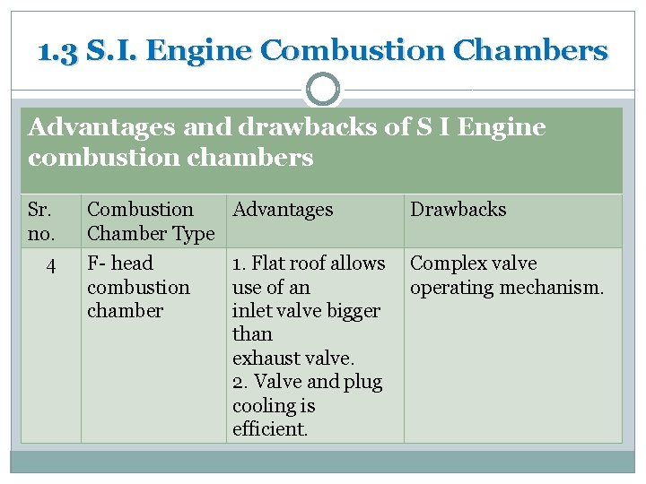
1. 3 S. I. Engine Combustion Chambers Advantages and drawbacks of S I Engine combustion chambers Sr. no. 4 Combustion Advantages Chamber Type Drawbacks F- head combustion chamber Complex valve operating mechanism. 1. Flat roof allows use of an inlet valve bigger than exhaust valve. 2. Valve and plug cooling is efficient.
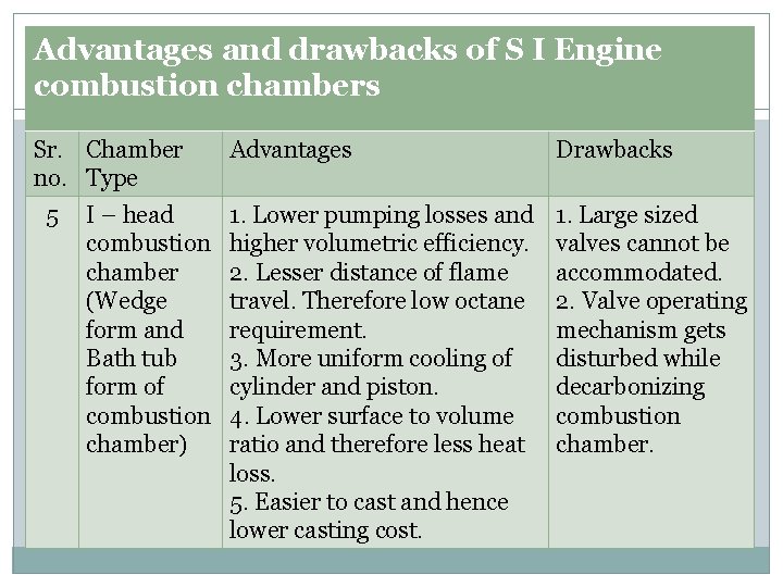
Advantages and drawbacks of S I Engine combustion chambers Sr. Chamber no. Type 5 I – head combustion chamber (Wedge form and Bath tub form of combustion chamber) Advantages Drawbacks 1. Lower pumping losses and higher volumetric efficiency. 2. Lesser distance of flame travel. Therefore low octane requirement. 3. More uniform cooling of cylinder and piston. 4. Lower surface to volume ratio and therefore less heat loss. 5. Easier to cast and hence lower casting cost. 1. Large sized valves cannot be accommodated. 2. Valve operating mechanism gets disturbed while decarbonizing combustion chamber.
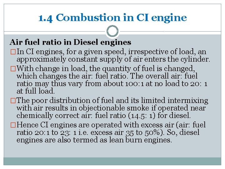
1. 4 Combustion in CI engine Air fuel ratio in Diesel engines �In CI engines, for a given speed, irrespective of load, an approximately constant supply of air enters the cylinder. �With change in load, the quantity of fuel is changed, which changes the air: fuel ratio. The overall air: fuel ratio may thus vary from about 100: 1 at no load to 20: 1 at full load. �The poor distribution of fuel and its limited intermixing with air results in objectionable smoke if operated near chemically correct air: fuel ratio (14. 5: 1) for diesel. �Hence CI engines are operated with excess air (air: fuel ratio 20: 1 to 23: 1 i. e. excess air 35 to 50%). So, diesel engines are also termed as lean burn engines.
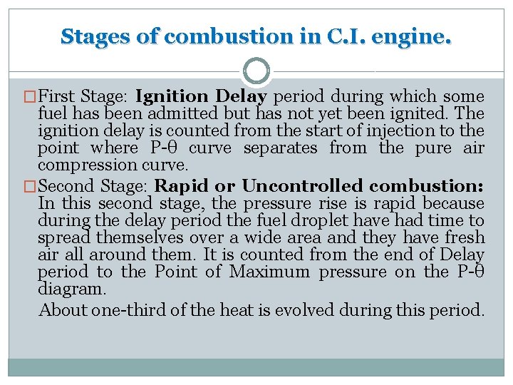
Stages of combustion in C. I. engine. �First Stage: Ignition Delay period during which some fuel has been admitted but has not yet been ignited. The ignition delay is counted from the start of injection to the point where P-θ curve separates from the pure air compression curve. �Second Stage: Rapid or Uncontrolled combustion: In this second stage, the pressure rise is rapid because during the delay period the fuel droplet have had time to spread themselves over a wide area and they have fresh air all around them. It is counted from the end of Delay period to the Point of Maximum pressure on the P-θ diagram. About one-third of the heat is evolved during this period.
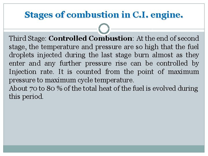
Stages of combustion in C. I. engine. Third Stage: Controlled Combustion: At the end of second stage, the temperature and pressure are so high that the fuel droplets injected during the last stage burn almost as they enter and any further pressure rise can be controlled by Injection rate. It is counted from the point of maximum pressure to maximum cycle temperature. About 70 to 80 % of the total heat of the fuel is evolved during this period.
Stages of combustion in C. I. engine. • Fourth Stage: Afterburning: Because of poor distribution of the fuel particles, combustion continues during part of the remainder of the expansion stroke. This after-burning can be called the fourth stage of combustion. The duration of after-burning phase may correspond to 70 -80 degrees of crank travel from TDC. Total heat evolved by the end of the combustion process is 95 to 97 % and 3 to 5% of heat goes as unburnt fuel in exhaust.
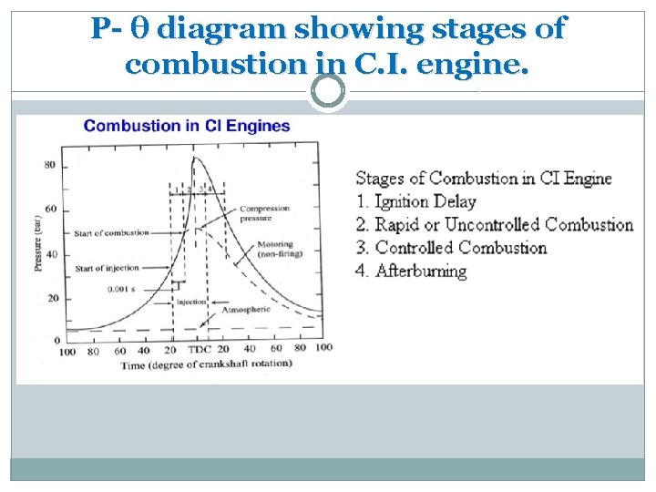
P- θ diagram showing stages of combustion in C. I. engine.
Ignition Delay period in C. I. Engine Ignition delay is the period during which some fuel has been admitted but has not yet been ignited. It is counted from the start of injection to the point where P-θ curve separates from pure air compression curve. The ignition delay can be roughly divided into two parts: Physical delay and chemical delay. � Physical Delay: The period of physical delay is the time between the beginning of injection and the attainment of chemical reaction conditions. In the physical delay period, the fuel is atomized, vaporized, mixed with air , and raised in temperature. � Chemical Delay: in this period, pre-flame reactions start slowly and then accelerate until local inflammation or ignition takes place. At high temperatures, chemical reaction is quicker and physical delay is longer than chemical delay.
Factors affecting Ignition Delay period � Fuel: Lower self ignition temperature means a lower delay period. Higher Cetane number means a lower delay period and smooth engine operation. � Intake Temperature: Increase in intake temperature would result in increase in compressed air temperature which would reduce the delay period. � Compression ratio: Increase in compression ratio reduces delay period as it raises both temperature and density. � Type of combustion chamber: A pre-combustion chamber gives shorter delay compared to an open type of combustion chamber. � Injection advance: Delay period increases with increase in injection advance angle. (with increase in injection angle, pressure and temperature are lower when injection begins)
Diesel Knock �If the Ignition delay period is long, a large amount of fuel will be injected and accumulated in the chamber. The auto-ignition of this large amount of fuel may cause high rate of pressure rise and high maximum pressure which may cause Knocking in diesel engines. �A long delay period not only increases the amount of fuel injected by the moment of ignition, but also improves the homogeneity of the fuel- air mixture and its chemical preparedness for explosion type of self-ignition similar to detonation in SI engines.
Methods of controlling Diesel Knock The diesel knock can be controlled by reducing delay period. The delay is reduced by the following. 1. High charge temperature 2. High fuel temperature. 3. Good turbulence. 4. A fuel with short induction period. 5. By using Ignition accelerators like Amyl Nitrate.
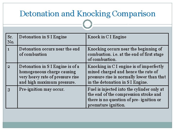
Detonation and Knocking Comparison Sr. Detonation in S I Engine No. Knock in C I Engine 1 Detonation occurs near the end of combustion Knocking occurs near the beginning of combustion. i. e. at the end of first stage of combustion. 2 Detonation in S I Engine is of a homogeneous charge causing very heavy rate of pressure rise and high maximum pressure. Knocking in C I engine is of imperfectly mixed charged and hence the rate of pressure rise is normally lower than that in the detonation in S I Engine. 3 Pre-ignition may occur. Fuel is injected into the cylinder only at the end of the compression stroke and there is no question of pre- ignition or premature ignition.
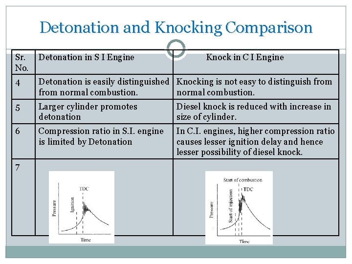
Detonation and Knocking Comparison Sr. Detonation in S I Engine No. Knock in C I Engine 4 Detonation is easily distinguished Knocking is not easy to distinguish from normal combustion. 5 Larger cylinder promotes detonation Diesel knock is reduced with increase in size of cylinder. 6 Compression ratio in S. I. engine is limited by Detonation In C. I. engines, higher compression ratio causes lesser ignition delay and hence lesser possibility of diesel knock. 7
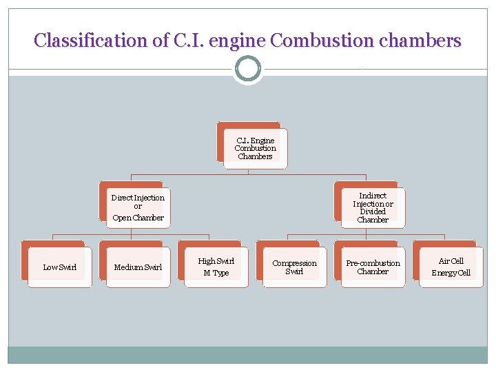
C. I. Engine Combustion Chambers C. I. Engines are classified on the basis of method of generating swirl. There are four types of combustion chambers. 1. Open Combustion chambers 2. Divided or turbulent swirl chambers 3. Pre-combustion chambers 4. Air cell combustion chambers.
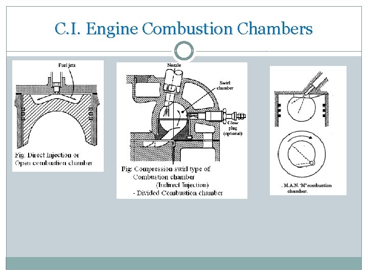
C. I. Engine Combustion Chambers 1. Open combustion chambers: The method of chambers swirl used in this type of combustion chamber is induction swirl. In induction swirl, flow of air is directed towards the cylinders during its entry. An open combustion chamber is one in which combustion space is essentially a simple cavity with little restriction and there are no large differences in pressure between different parts of chamber during the combustion process.
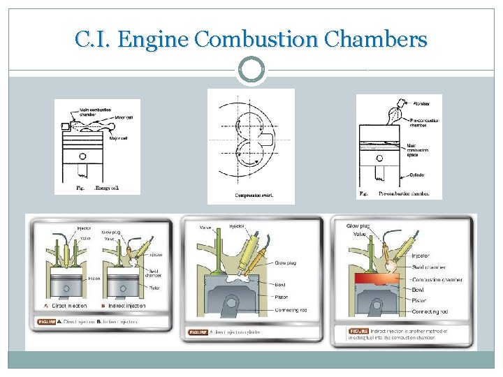
C. I. Engine Combustion Chambers 2. Divided or Turbulent swirl chambers: The chambers method of generating swirl in the divided chamber is by compression. Compression swirl is one in which air is forced through a tangential passage into a separate swirl chamber during compression stroke. A divided combustion chamber is defined as one in which the combustion space is divided into two or more distinct compartments between which there are restrictions or throats small enough so that considerable pressure difference occurs between them during combustion process.
C. I. Engine Combustion Chambers 3. Pre-combustion chamber: The type of swirl used chamber is combustion induced swirl. A pre-combustion chamber consist s of pre-combustion chamber or anti-chamber connected to the main chamber through a number of very small holes. Precombustion chamber contains 20 to 30 % of clearance volume. Pre-combustion chamber has multi-fuel capability without any modification in the injection system in the type of swirl used. i. e. combustion inducted swirl, swirl turbulence is created by use of initial pressure rise due to partial combustion.
C. I. Engine Combustion Chambers Air cell combustion chamber: The type of swirl used chamber in this combustion chamber is combustion induced swirl. Here there is no organized air swirl. The advantage for this type of combustion chamber are a. The maximum pressure on the main chamber is fairly low and hence it gives smooth running and easy starting. b. This type of combustion chamber is most suitable for comparatively small engines of medium duty where a relatively high fuel consumption can be tolerated. 4.
Classification of C. I. engine Combustion chambers C. I. Engine Combustion Chambers Indirect Injection or Divided Chamber Direct Injection or Open Chamber Low Swirl Medium Swirl High Swirl M Type Compression Swirl Pre-combustion Chamber Air Cell Energy Cell
C. I. Engine Combustion Chambers
C. I. Engine Combustion Chambers
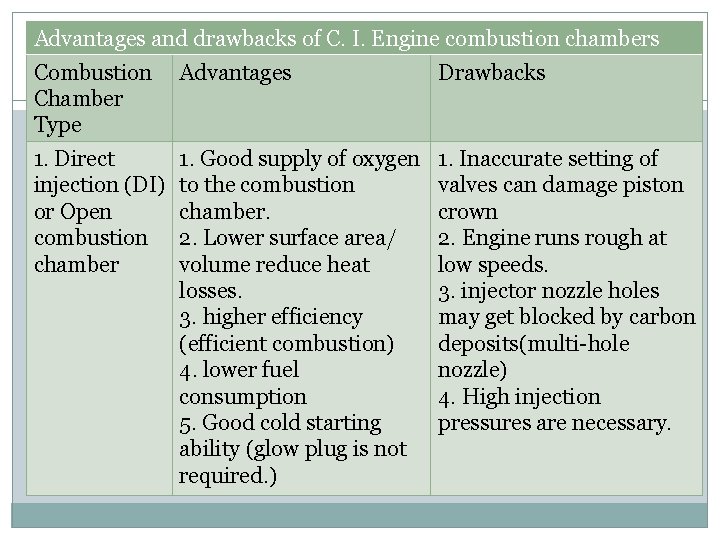
Advantages and drawbacks of C. I. Engine combustion chambers Combustion Advantages Chamber Type Drawbacks 1. Direct injection (DI) or Open combustion chamber 1. Inaccurate setting of valves can damage piston crown 2. Engine runs rough at low speeds. 3. injector nozzle holes may get blocked by carbon deposits(multi-hole nozzle) 4. High injection pressures are necessary. 1. Good supply of oxygen to the combustion chamber. 2. Lower surface area/ volume reduce heat losses. 3. higher efficiency (efficient combustion) 4. lower fuel consumption 5. Good cold starting ability (glow plug is not required. )
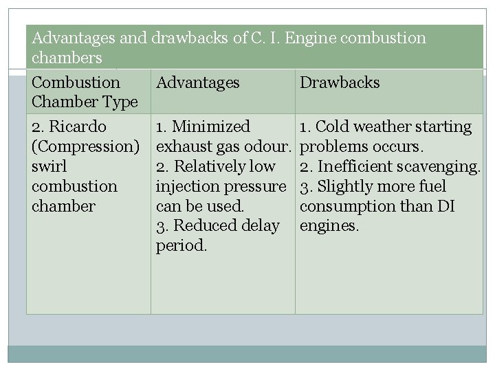
Advantages and drawbacks of C. I. Engine combustion chambers Combustion Advantages Chamber Type 2. Ricardo (Compression) swirl combustion chamber Drawbacks 1. Minimized 1. Cold weather starting exhaust gas odour. problems occurs. 2. Relatively low 2. Inefficient scavenging. injection pressure 3. Slightly more fuel can be used. consumption than DI 3. Reduced delay engines. period.
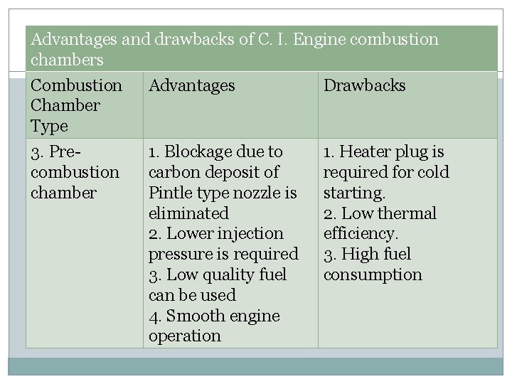
Advantages and drawbacks of C. I. Engine combustion chambers Combustion Chamber Type Advantages Drawbacks 3. Precombustion chamber 1. Blockage due to carbon deposit of Pintle type nozzle is eliminated 2. Lower injection pressure is required 3. Low quality fuel can be used 4. Smooth engine operation 1. Heater plug is required for cold starting. 2. Low thermal efficiency. 3. High fuel consumption
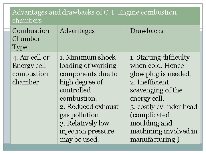
Advantages and drawbacks of C. I. Engine combustion chambers Combustion Chamber Type Advantages Drawbacks 4. Air cell or Energy cell combustion chamber 1. Minimum shock loading of working components due to high degree of controlled combustion. 2. Reduced exhaust gas pollution 3. Relatively low injection pressure may be used. 1. Starting difficulty when cold. Hence glow plug is needed. 2. Inefficient scavenging of the energy cell. 3. costly cylinder head (complicated moulding and machining involved in manufacturing. )
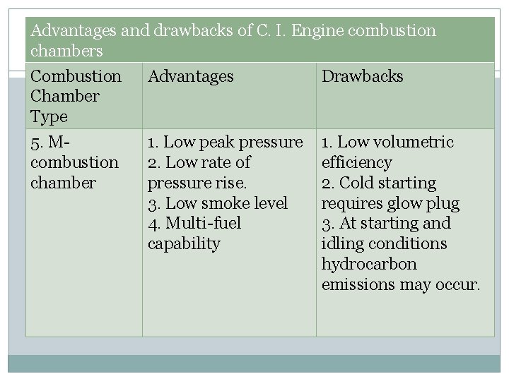
Advantages and drawbacks of C. I. Engine combustion chambers Combustion Chamber Type Advantages Drawbacks 5. M- combustion chamber 1. Low peak pressure 2. Low rate of pressure rise. 3. Low smoke level 4. Multi-fuel capability 1. Low volumetric efficiency 2. Cold starting requires glow plug 3. At starting and idling conditions hydrocarbon emissions may occur.
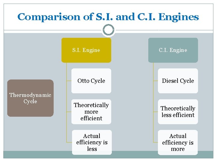
Comparison of S. I. and C. I. Engines S. I. Engine Thermodynamic Cycle C. I. Engine Otto Cycle Diesel Cycle Theoretically more efficient Theoretically less efficient Actual efficiency is less Actual efficiency is more
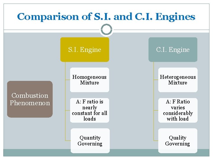
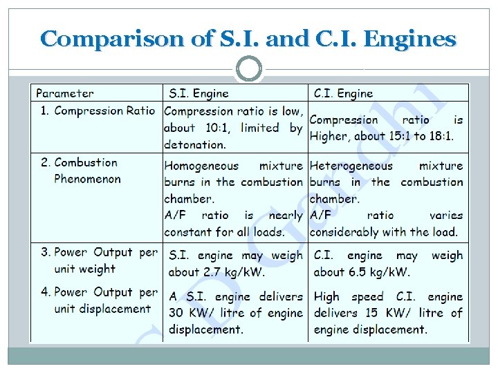
Comparison of S. I. and C. I. Engines S. I. Engine Combustion Phenomenon C. I. Engine Homogeneous Mixture Heterogeneous Mixture A: F ratio is nearly constant for all loads A: F Ratio varies considerably with load Quantity Governing Quality Governing
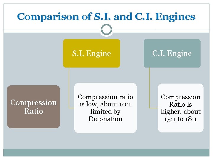
Comparison of S. I. and C. I. Engines S. I. Engine Compression Ratio Compression ratio is low, about 10: 1 limited by Detonation C. I. Engine Compression Ratio is higher, about 15: 1 to 18: 1
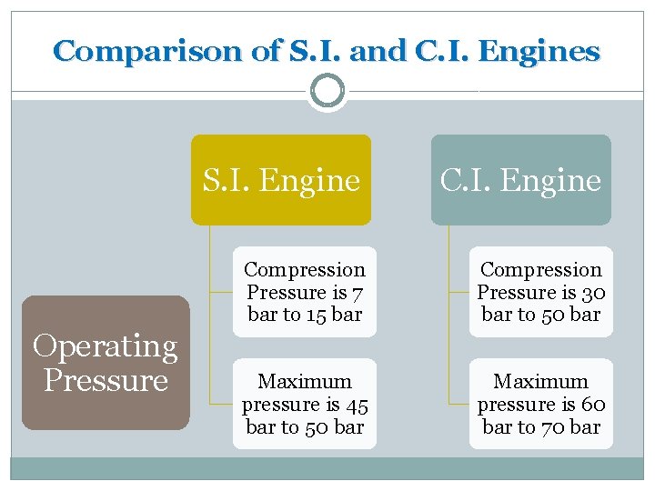
Comparison of S. I. and C. I. Engines S. I. Engine Operating Pressure C. I. Engine Compression Pressure is 7 bar to 15 bar Compression Pressure is 30 bar to 50 bar Maximum pressure is 45 bar to 50 bar Maximum pressure is 60 bar to 70 bar
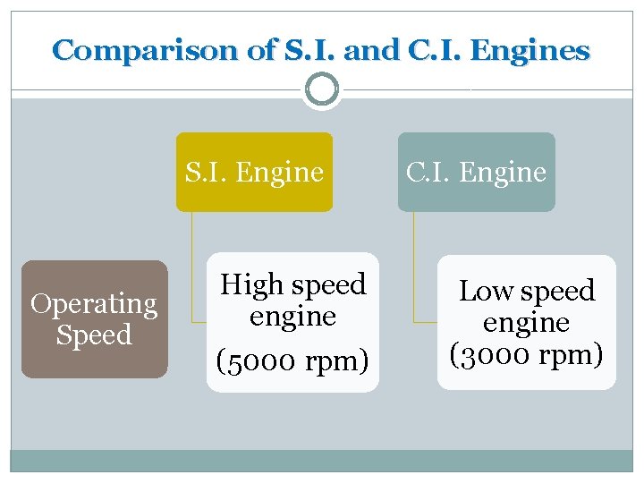
Comparison of S. I. and C. I. Engines S. I. Engine Operating Speed High speed engine (5000 rpm) C. I. Engine Low speed engine (3000 rpm)
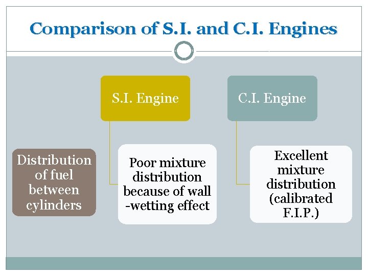
Comparison of S. I. and C. I. Engines S. I. Engine Distribution of fuel between cylinders Poor mixture distribution because of wall -wetting effect C. I. Engine Excellent mixture distribution (calibrated F. I. P. )
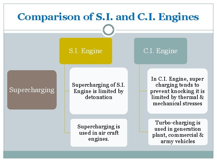
Comparison of S. I. and C. I. Engines S. I. Engine Supercharging C. I. Engine Supercharging of S. I. Engine is limited by detonation In C. I. Engine, super charging tends to prevent knocking it is limited by thermal & mechanical stresses Supercharging is used in air craft engines. Turbo-charging is used in generation plant, commercial & army vehicles
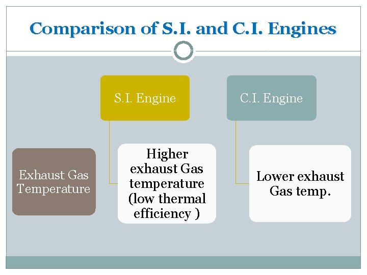
Comparison of S. I. and C. I. Engines S. I. Engine Exhaust Gas Temperature Higher exhaust Gas temperature (low thermal efficiency ) C. I. Engine Lower exhaust Gas temp.
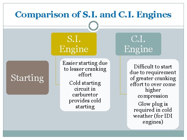
Comparison of S. I. and C. I. Engines S. I. Engine Starting Easier starting due to lesser cranking effort Cold starting circuit in carburetor provides cold starting C. I. Engine Difficult to start due to requirement of greater cranking effort to over come higher compression Glow plug is required in cold weather (for IDI engines)
Comparison of S. I. and C. I. Engines

- Slides: 72