
A Transport Layer Approach for Achieving Aggregate Bandwidths
A Transport Layer Approach for Achieving Aggregate Bandwidths on Multi-homed Mobile Hosts Hung-Yun Hsieh and Raghupathy Sivakumar GNAN Research Group School of Electrical and Computer Engineering Georgia Institute of Technology September 26, 2002
Outline n n n Introduction Motivation Design Protocol Evaluation Conclusions
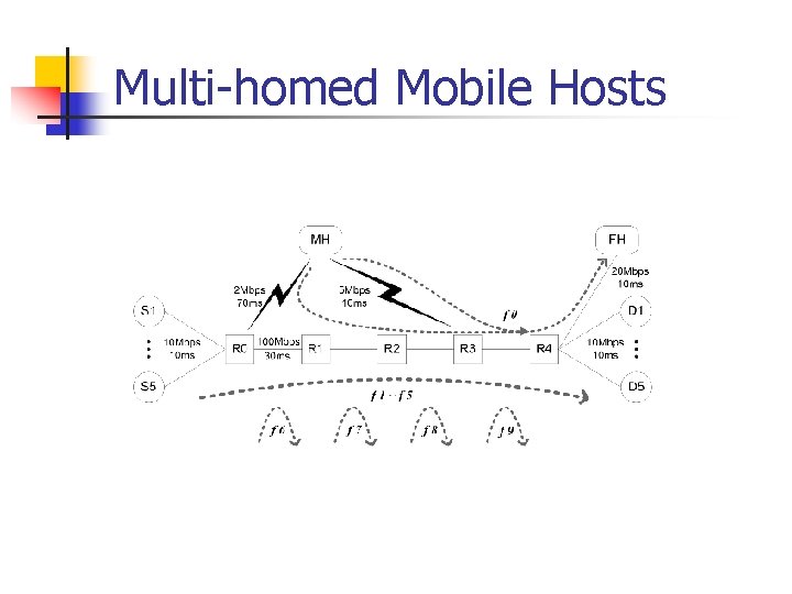
Introduction n n A multitude of wireless access technologies How can these technologies co-exist in providing the best service to a multi-homed mobile user? F Use only the interface with the highest data rate at any given time Ø Objective n n Allow simultaneous use of multiple wireless access technologies (striping) Design a transport layer protocol that provides reliable and sequenced delivery like in TCP, and achieves effective bandwidth aggregation
Why Not Lower Layers? n Link layer striping [Adiseshu ’ 96, Snoeren ’ 99] Stripe according to estimates of link bandwidths û Optimal link layer striping optimal bandwidth aggregation across multi-hop paths û Not applicable to multi-homed mobile hosts n n Network layer striping [Phatak ’ 02] IP performs tunneling and striping û TCP’s RTT estimates lose meaning û TCP adversely reacts to packet reordering n Ø Lower layer approaches fail due to the multihop nature of paths and TCP’s reliance on FIFO delivery!
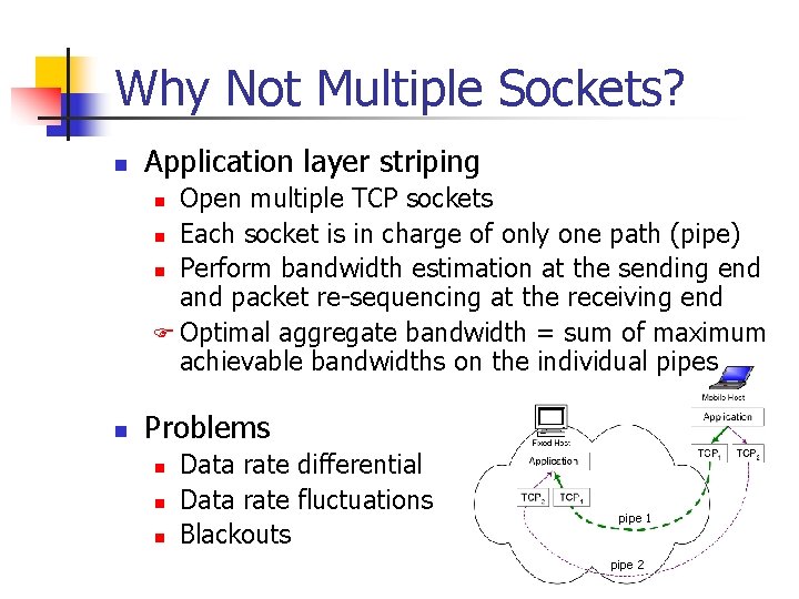
Why Not Multiple Sockets? n Application layer striping Open multiple TCP sockets n Each socket is in charge of only one path (pipe) n Perform bandwidth estimation at the sending end and packet re-sequencing at the receiving end F Optimal aggregate bandwidth = sum of maximum achievable bandwidths on the individual pipes n n Problems n n n Data rate differential Data rate fluctuations Blackouts pipe 1 pipe 2
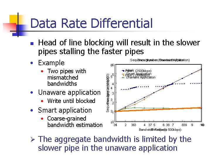
Data Rate Differential n Head of line blocking will result in the slower pipes stalling the faster pipes • Example • Unaware application • Write until blocked • Smart application • Coarse-grained bandwidth estimation Ø 66 Sequence Number(Mbps) (x 1000) Throughput • Two pipes with mismatched bandwidths Sequence Throughput Number vs. (Unaware Bandwidth Application) Ratio 5 5 Ideal 1 (2500 kbps) Pipe Smart Application Pipe 2 (500 kbps) Unaware Application 4 4 3 3 2 21 10 35 1 2 363 4 37 5 6 38 7 839 Bandwidth Time Ratio (sec) (to 500 kbps) The aggregate bandwidth is limited by the slower pipe in the unaware application 9 40 10
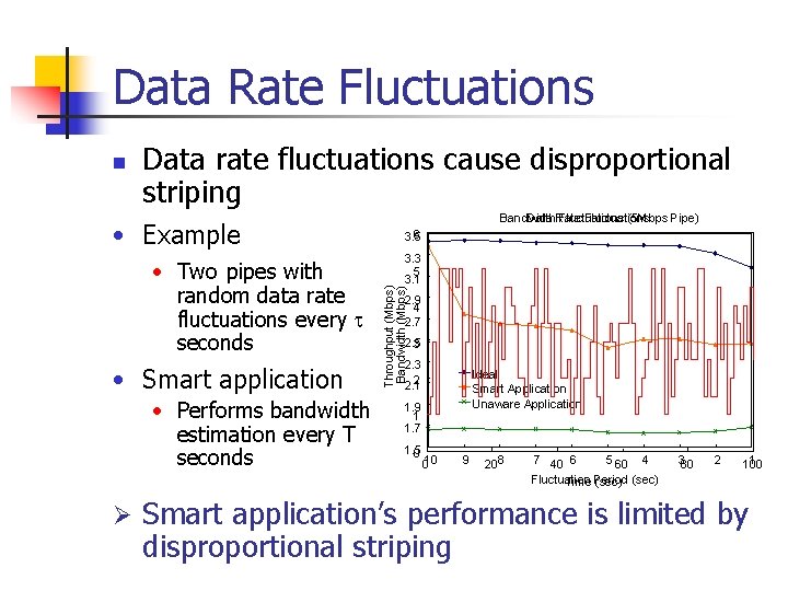
Data Rate Fluctuations Data rate fluctuations cause disproportional striping • Example • Two pipes with random data rate fluctuations every t seconds • Smart application • Performs bandwidth estimation every T seconds Ø Data Rate Fluctuations Bandwidth Fluctuations (5 Mbps Pipe) 6 3. 5 3. 3 5 3. 1 Throughput (Mbps) Bandwidth (Mbps) n 2. 9 4 2. 7 2. 5 3 2 2. 1 Ideal Smart Application Unaware Application 1. 9 1 1. 7 1. 5 0 010 9 208 7 40 6 5 60 4 Fluctuation Time Period (sec) 380 2 1 100 Smart application’s performance is limited by disproportional striping
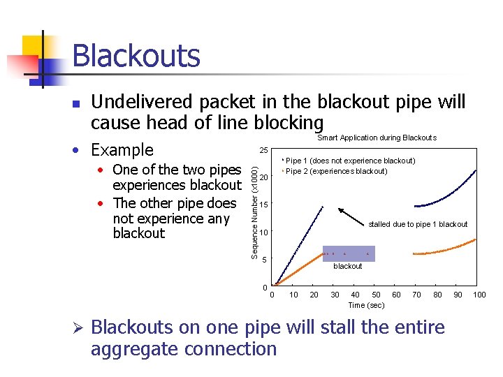
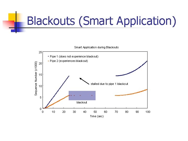
Blackouts n Undelivered packet in the blackout pipe will cause head of line blocking Smart Application during Blackouts • Example Sequence Number (x 1000) • One of the two pipes experiences blackout • The other pipe does not experience any blackout 25 20 15 stalled due to pipe 1 blackout 10 5 0 Ø Pipe 1 (does not experience blackout) Pipe 2 (experiences blackout) blackout 0 10 20 30 40 50 Time (sec) 60 70 80 Blackouts on one pipe will stall the entire aggregate connection 90 100
Agenda n n n Introduction Motivation p. TCP Design p. TCP Protocol Evaluation Conclusions
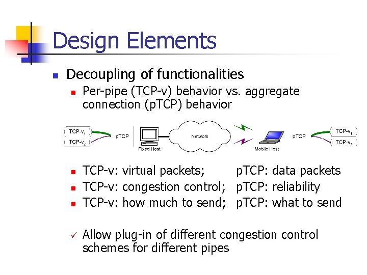
Design Elements n Decoupling of functionalities n n ü Per-pipe (TCP-v) behavior vs. aggregate connection (p. TCP) behavior TCP-v: virtual packets; p. TCP: data packets TCP-v: congestion control; p. TCP: reliability TCP-v: how much to send; p. TCP: what to send Allow plug-in of different congestion control schemes for different pipes
Design Elements n Congestion window based striping n n n Dynamic reassignment n n n A packet is given to a TCP-v only when its congestion window has space Reuse TCP’s congestion control for bandwidth estimation Reassign packets that fall out of TCP-v’s window Avoid packets being held up by one pipe Redundant striping n n Redundantly stripe the first packet after timeouts Allow the concerned pipe to probe while not potentially stalling the rest
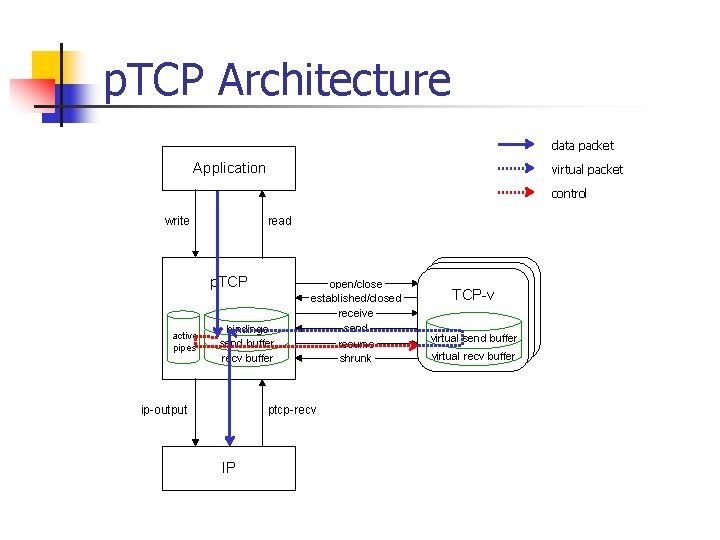
p. TCP Architecture data packet Application virtual packet control write read p. TCP active pipes bindings send buffer recv buffer ip-output open/close established/closed receive send resume shrunk ptcp-recv IP TCP-v virtual send buffer virtual recv buffer
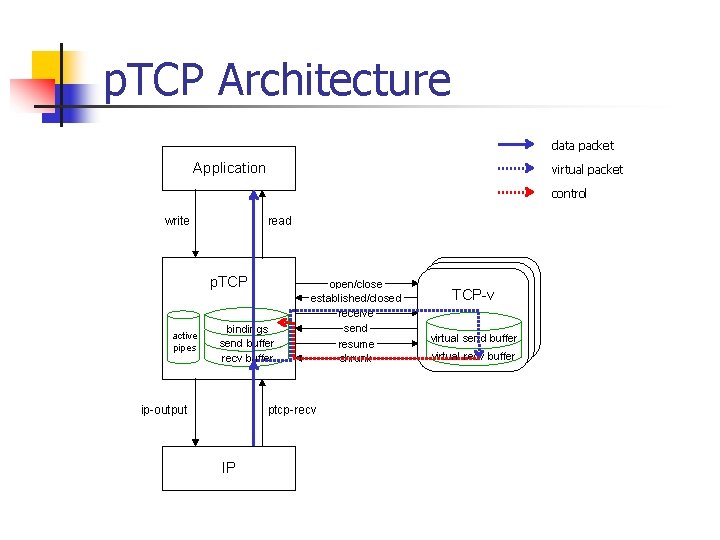
p. TCP Architecture data packet Application virtual packet control write read p. TCP active pipes bindings send buffer recv buffer ip-output open/close established/closed receive send resume shrunk ptcp-recv IP TCP-v virtual send buffer virtual recv buffer
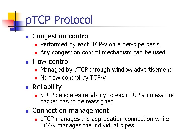
p. TCP Protocol n Congestion control n n n Flow control n n n Managed by p. TCP through window advertisement No flow control by TCP-v Reliability n n Performed by each TCP-v on a per-pipe basis Any congestion control mechanism can be used p. TCP delegates reliability to each TCP-v unless the packet has to be reassigned Connection management n p. TCP manages the aggregation connection while TCP-v manages the individual pipes
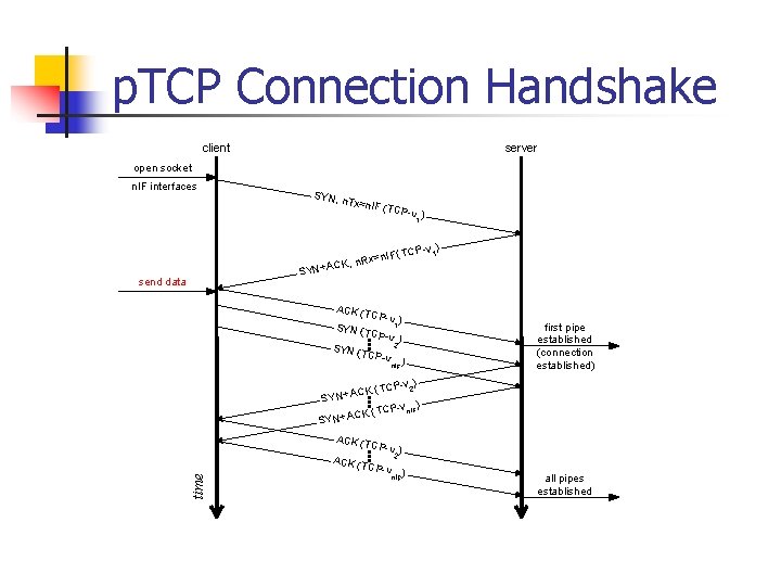
p. TCP Connection Handshake client server open socket n. IF interfaces SY N, n T x=n IF (TCP-v 1 ) ) (TCP -v 1 IF n = x CK , n. R S YN +A send data ACK (TC P- v ) 1 SY N (T CP -v ) 2 SY N (T CP -v n. IF ) first pipe established (connection established) time -v ) K (TCP 2 C A + SY N -v ) K ( TCP n. IF C A + SY N ACK (TC P- v ) 2 ACK (T C P-v n. IF) all pipes established
Agenda n n n Introduction Motivation Design Protocol Evaluation Conclusions
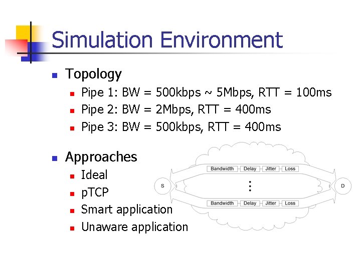
Simulation Environment n Topology n n Pipe 1: BW = 500 kbps ~ 5 Mbps, RTT = 100 ms Pipe 2: BW = 2 Mbps, RTT = 400 ms Pipe 3: BW = 500 kbps, RTT = 400 ms Approaches n n Ideal p. TCP Smart application Unaware application
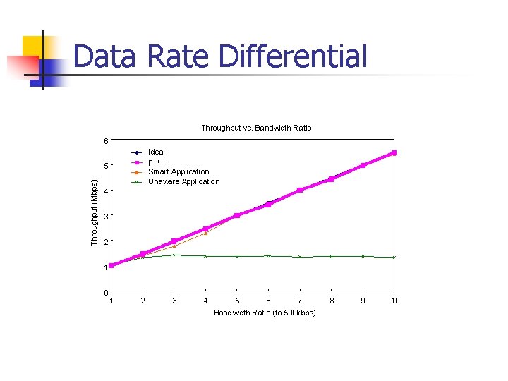
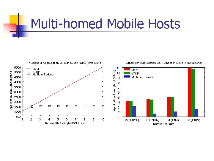
Data Rate Differential Throughput vs. Bandwidth Ratio 6 Ideal p. TCP Smart Application Unaware Application Throughput (Mbps) 5 4 3 2 1 0 1 2 3 4 5 6 7 Bandwidth Ratio (to 500 kbps) 8 9 10
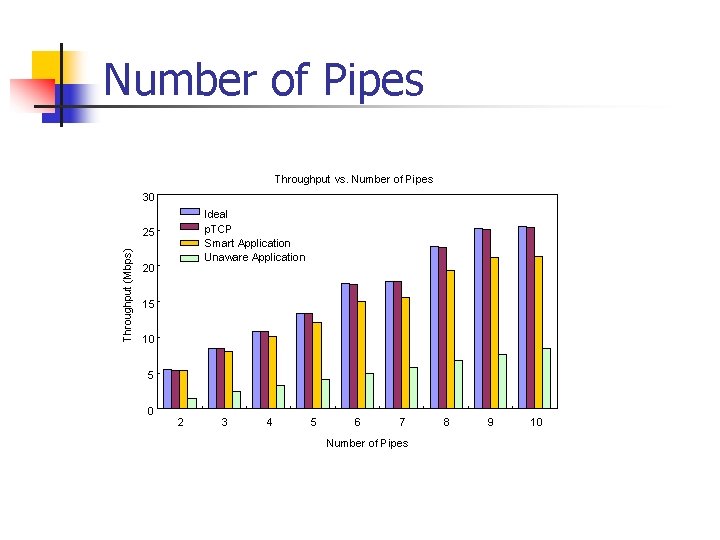
Number of Pipes Throughput vs. Number of Pipes 30 Ideal p. TCP Smart Application Unaware Application Throughput (Mbps) 25 20 15 10 5 0 2 3 4 5 6 7 Number of Pipes 8 9 10
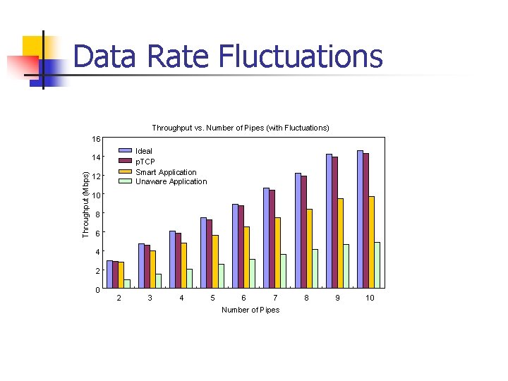
Data Rate Fluctuations Throughput vs. Number of Pipes (with Fluctuations) 16 Ideal p. TCP Smart Application Unaware Application Throughput (Mbps) 14 12 10 8 6 4 2 0 2 3 4 5 6 7 Number of Pipes 8 9 10
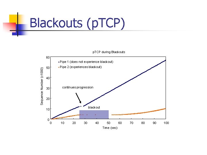
Blackouts (p. TCP) p. TCP during Blackouts 60 Sequence Number (x 1000) Pipe 1 (does not experience blackout) Pipe 2 (experiences blackout) 50 40 continues progression 30 20 blackout 10 0 0 10 20 30 40 50 Time (sec) 60 70 80 90 100
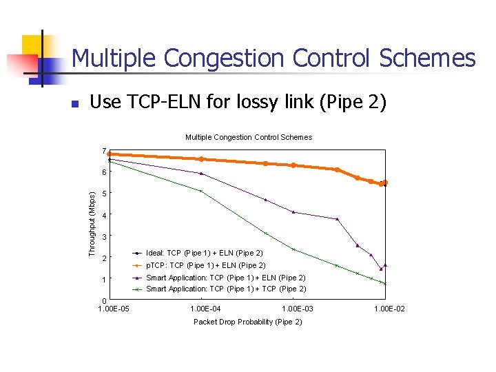
Multiple Congestion Control Schemes Use TCP-ELN for lossy link (Pipe 2) Multiple Congestion Control Schemes 7 6 Throughput (Mbps) n 5 4 3 2 1 Ideal: TCP (Pipe 1) + ELN (Pipe 2) p. TCP: TCP (Pipe 1) + ELN (Pipe 2) Smart Application: TCP (Pipe 1) + TCP (Pipe 2) 0 1. 00 E-05 1. 00 E-04 1. 00 E-03 Packet Drop Probability (Pipe 2) 1. 00 E-02
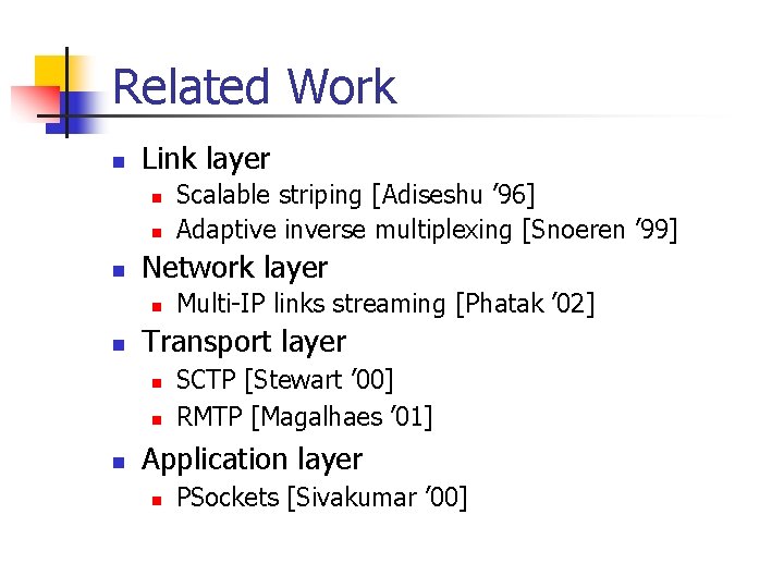
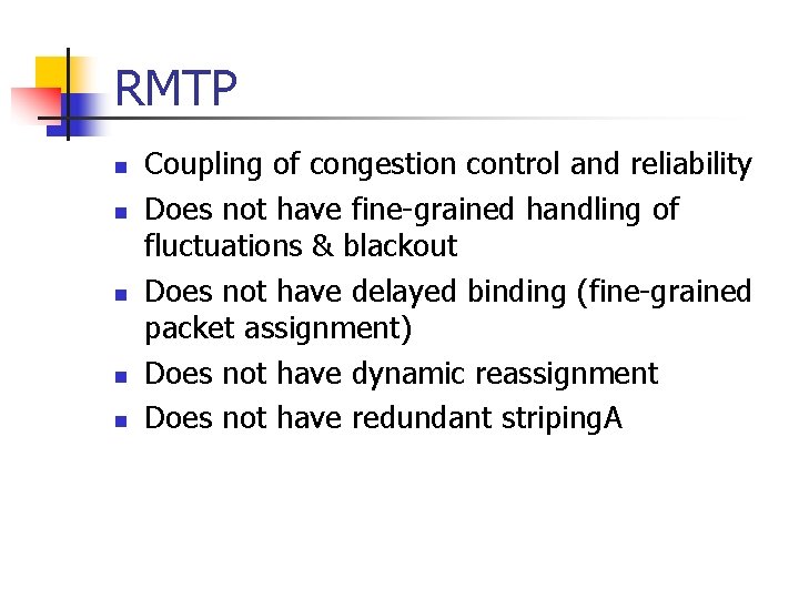
Related Work n Link layer n n n Network layer n n Multi-IP links streaming [Phatak ’ 02] Transport layer n n n Scalable striping [Adiseshu ’ 96] Adaptive inverse multiplexing [Snoeren ’ 99] SCTP [Stewart ’ 00] RMTP [Magalhaes ’ 01] Application layer n PSockets [Sivakumar ’ 00]
Conclusions n n n v Bandwidth aggregation can be used to provide better service to multi-homed mobile hosts A transport layer approach is more effective than other layers in the target environment p. TCP achieves effective bandwidth aggregation despite the data rate mismatch, fluctuations, and blackouts of different pipes For more information: http: //www. ece. gatech. edu/research/GNAN
Application Complexity n Sophisticated implementation n It is not desirable to overload application n n Need to re-implement most TCP functionalities Very complicated bandwidth estimation scheme at least the time-granularity of TCP Not application specific functionalities Data rate differential can be solved using a larger re-sequencing buffer n n Need larger buffer than p. TCP uses (transport layer buffering) Buffer over-provisioning
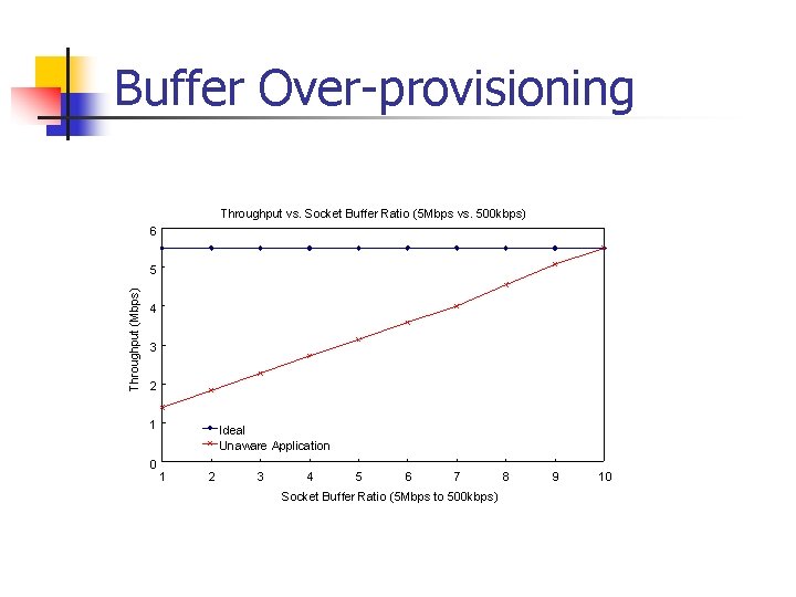
Buffer Over-provisioning Throughput vs. Socket Buffer Ratio (5 Mbps vs. 500 kbps) 6 Throughput (Mbps) 5 4 3 2 1 0 Ideal Unaware Application 1 2 3 4 5 6 7 Socket Buffer Ratio (5 Mbps to 500 kbps) 8 9 10
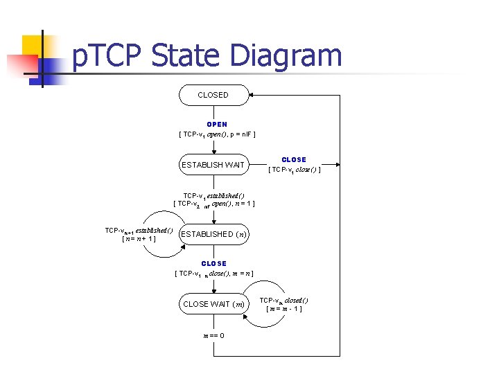
p. TCP State Diagram CLOSED OPEN [ TCP-v 1 open( ), p = n. IF ] ESTABLISH WAIT CLOSE [ TCP-v 1 close( ) ] TCP-v 1 established( ) [ TCP-v 2. . . n. IF open( ), n = 1 ] TCP-v n +1 established( ) [ n= n + 1 ] ESTABLISHED ( n) CLOSE [ TCP-v 1. . . n close( ), m = n ] CLOSE WAIT ( m) m == 0 TCP-v m closed( ) [ m=m -1]
Multi-homed Mobile Hosts
Multi-homed Mobile Hosts Throughput Aggregation vs. Bandwidth Ratio (Two Links) 11 Ideal p. TCP Multiple Sockets 5000 4500 Application Throughput (Mbps) Application Throughput (kbps) 5500 4000 3500 3000 2500 2000 1500 1000 500 1 2 3 4 5 6 7 8 Bandwidth Ratio (to 500 kbps) Bandwidth Aggregation vs. Number of Links (Fluctuations) 9 10 10 9 Ideal p. TCP Multiple Sockets 8 7 6 5 4 3 2 1 2 (5 M+2 M) 3 (+500 k) 4 (+1 M) Number of Links 5 (+10 M)
RMTP n n n Coupling of congestion control and reliability Does not have fine-grained handling of fluctuations & blackout Does not have delayed binding (fine-grained packet assignment) Does not have dynamic reassignment Does not have redundant striping. A
Blackouts (Smart Application) Smart Application during Blackouts 25 Sequence Number (x 1000) Pipe 1 (does not experience blackout) Pipe 2 (experiences blackout) 20 15 stalled due to pipe 1 blackout 10 5 blackout 0 0 10 20 30 40 50 Time (sec) 60 70 80 90 100
Issues n n n Bandwidth-delay product TCP friendliness Backward compatibility Complexity Handoffs
- Slides: 33