A Systolic FFT Architecture for Real Time FPGA


- Slides: 33
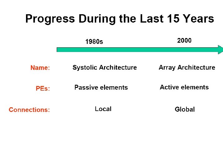
A Systolic FFT Architecture for Real Time FPGA Systems
Radar Processing Application ADC x 1. 2 GSPS 32 K Correlation ADC y 1. 2 GSPS I/Q FFT FIFO Conjugate 8 K FFT bottleneck • Real-time • Complex • 0. 6 GSPS input (16 -bits) • 1. 2 GSPS output (12 -bits) × I/Q FFT FIFO + × + FIFO
Evaluation Scorecard • The design changes will be scored based on the following metrics: Length of FFT IO pins Butterflies Multipliers Adder/subtractors Shift registers Size 16 8192 Pins ? ? ? Fly ? ? ? Mult ? ? ? Add ? ? ? Shift ? ? ?
Outline • Introduction • Parallel architecture – Data flow graph – Effects of serial input • Systolic architecture • Performance summary • Conclusions
Baseline Parallel Architecture Size 16 8192 1 1 Pins 448 229 K 2 2 Fly 32 53 K 3 3 Mult 4 4 Add 5 5 Shift 0 0 6 6 7 7 8 8 9 9 10 10 11 11 12 12 13 13 14 14 15 15 16 16 Parallel FFT • Butterfly structure • Removes redundant calculation
Complex Butterfly • Butterfly contains – 1 complex addition – 1 complex subtraction – 1 complex, constant multiply u v × Size 16 8192 Pins 448 229 K Fly 32 53 K 0 0 Mult Add Shift + x - y
Complex Addition • Complex addition adds the real and imaginary parts separately: 2 adds a c b d + real + imag Size 16 8192 Pins 448 229 K Fly 32 53 K Add 128 213 K Shift 0 0 Mult
Complex Multiply • The FOIL method of multiplying complex numbers: 4 multiplies and 2 adds a × c × b × d × - real + imag Size 16 8192 Pins 448 229 K Fly 32 53 K Mult 128 213 K Add 192 320 K Shift 0 0
Efficient Complex Multiply • Another approach requires fewer multiplies: 16 8192 Pins 448 229 K Fly 32 53 K Mult 96 159 K 75% Add 288 480 K 150% Shift 0 0 3 multiplies and 5 adds a - b + c d - × × × Size - real + imag
Parallel-Pipelined Architecture Size 16 8192 1 1 Pins 448 229 K 2 2 Fly 32 53 K 3 3 Mult 96 159 K 4 4 Add 288 480 K 5 5 Shift 0 0 6 6 7 7 8 8 9 9 10 10 11 11 12 12 13 13 14 14 15 15 16 16 A pipelined version • IO Bound • 100% Efficient
Serial Input Size 16 8192 . 01% 1 1 Pins 28 28 2 2 Fly 32 53 K 3 3 Mult 96 159 K 4 4 Add 288 480 K 5 5 Shift 0 0 6 6 7 7 8 8 9 9 10 10 11 11 12 12 13 13 14 14 15 15 16 16 A serial version • IO-rate matches A/D • 6. 25% Efficient
Outline • Introduction • Parallel architecture • Systolic architecture – Serial implementation – Application specific optimizations • Performance summary • Conclusions
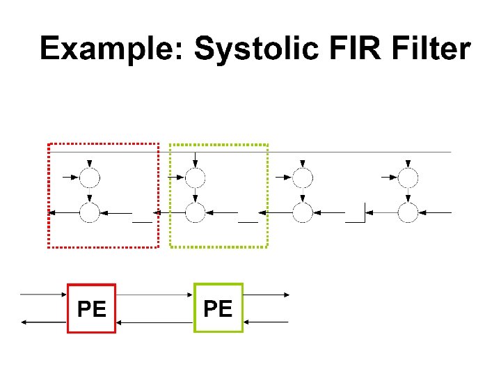
Serial Architecture • The parallel architecture can be collapsed – – One butterfly per stage Consumes 1 sample per cycle Same latency and throughput More efficient design Stage 1 Stage 2 Stage 3 50% Efficiency Size 16 8192 Pins 28 28 Fly 4 13 . 03% Mult 12 39 . 03% Add 36 117 . 03% Shift 22 12 K Stage 4
High Level View • Replace complex structure with an abstract cell which contains: – FIFOs – Butterfly – Switch network Size 16 8192 Pins 28 28 Fly 4 13 Mult 12 39 Add 36 117 Shift 22 12 K 1 2 3 4 Stage 1 Stage 2 Stage 3 Stage 4
8192 -Point Architecture • • Requires 13 stages Fixed point arithmetic Varies the dynamic range to increase accuracy Overflow replaced with saturated value 1 2 3 4 5 6 7 8 9 Size 16 8192 Pins 28 28 Fly 4 13 Mult 12 39 Add 36 117 Shift 22 12 K 10 11 12 13 4 int 5 int 6 int 7 int 8 int 9 int 10 int 4 frac 13 frac 12 frac 11 frac 10 frac 9 frac 8 frac • • Multipliers limit design to 18 -bits and 150 MHz Achieves 70 d. B of accuracy 0110. 0101
Increase Parallelism Add more pipelines • Design limited to 150 MHz by multipliers • I/Q module generate 600 MSPS • Meets real-time requirement through parallelism Size 16 8192 Pins 112 400% Fly 16 52 400% Mult 48 156 400% Add 144 468 400% Shift 16 12 K 100% 1 2 3 4 5 6 7 8 9 10 11 12 13
Simplification Target application allows a specific simplification • Pads a 4096 -point sequence with 4096 zeros • Removes 1 st stage multipliers and adders • Achieves 100% efficiency in steady state Size 16 8192 Pins 160 143% Fly 16 52 Mult 36 144 92% Add 108 432 92% Shift 4 8 K 67% 1 2 3 4 5 6 7 8 9 10 11 12 13
Outline • Introduction • Parallel architecture • Systolic architecture • Performance summary – Power, operations per second – FPGA resources, frequency – Latency, throughput • Conclusions
Results The current implementation has been placed on a Virtex II 8000 and verified at 150 MHz • • Power: 22 Watts @ 65 C GOPS: 86 total @ 3. 9 GOPS/Watt • FPGA resources (XC 2 V 8000) – – • • • Multipliers: 144 (85%) LUTs and SRLs: 39, 453 (42%) Block. RAM: 56 (33%) Filp flops: 35, 861 (38%) Frequency: 150 MHz Latency: 1127 cycles Throughput: 1. 2 GSPS
Outline • Introduction • Parallel architecture • Systolic architecture • Performance summary • Conclusions – Applicability to other platforms – Future work
Conclusions • Created a high performance, real-time FFT core – Low power (3. 9 GOPS/Watt) – High throughput (1. 2 GSPS), low latency (7. 6 µsec/sample) – Fixed-point (18 -bits), high accuracy (70 d. B) • General architecture – Extendable to a generic FPGA core – Retargetable to ASIC technology • Future work – Develop a parameterizable IP core generator
Sources • Fredrik Edman Preston Jackson, Cy Chan, Charles Rader, Jonathan Scalera, and Michael Vai HPEC 2004 29 September 2004