
A Study on MicroActuators for Atomic Force Microscopes
- Slides: 31
A Study on Micro-Actuators for Atomic Force Microscopes Chonghe Zhong Challenge the future 1
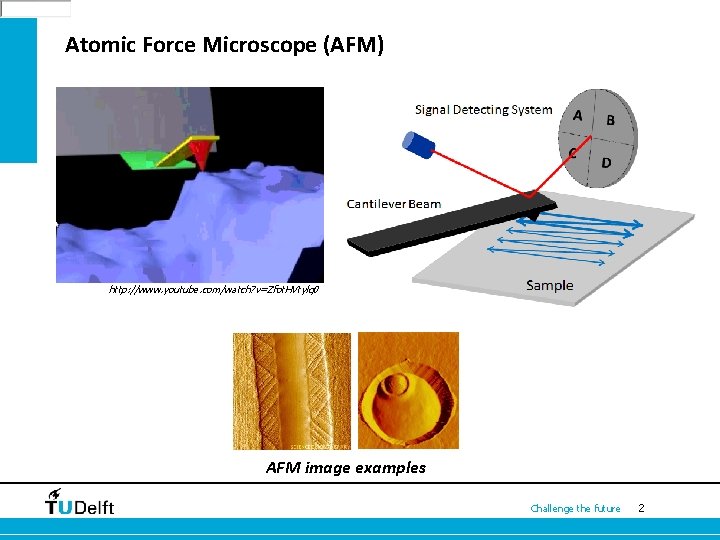
Atomic Force Microscope (AFM) http: //www. youtube. com/watch? v=Zfot. HVtylq 0 AFM image examples Challenge the future 2
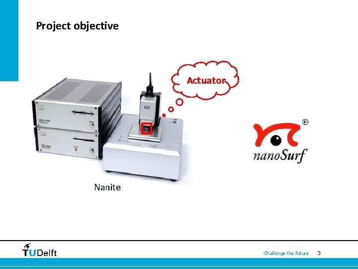
Project objective Actuator Nanite Challenge the future 3
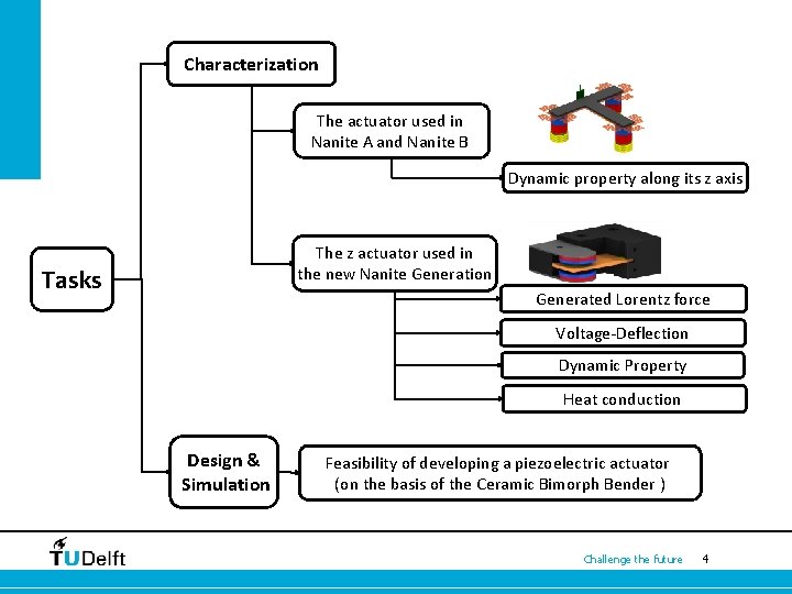
Characterization The actuator used in Nanite A and Nanite B Dynamic property along its z axis The z actuator used in the new Nanite Generation Tasks Generated Lorentz force Voltage-Deflection Dynamic Property Heat conduction Design & Simulation Feasibility of developing a piezoelectric actuator (on the basis of the Ceramic Bimorph Bender ) Challenge the future 4
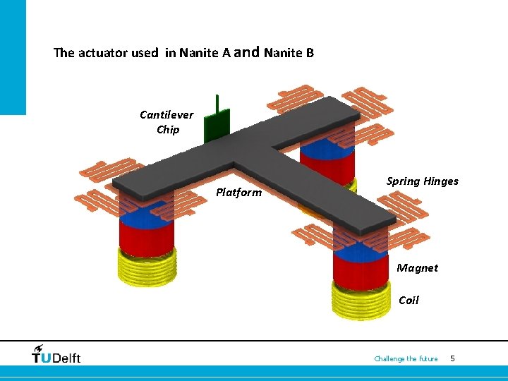
The actuator used in Nanite A and Nanite B Cantilever Chip z Platform Spring Hinges Magnet Coil Challenge the future 5
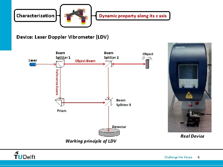
Characterization Dynamic property along its z axis Device: Laser Doppler Vibrometer (LDV) Working principle of LDV Real Device Challenge the future 6
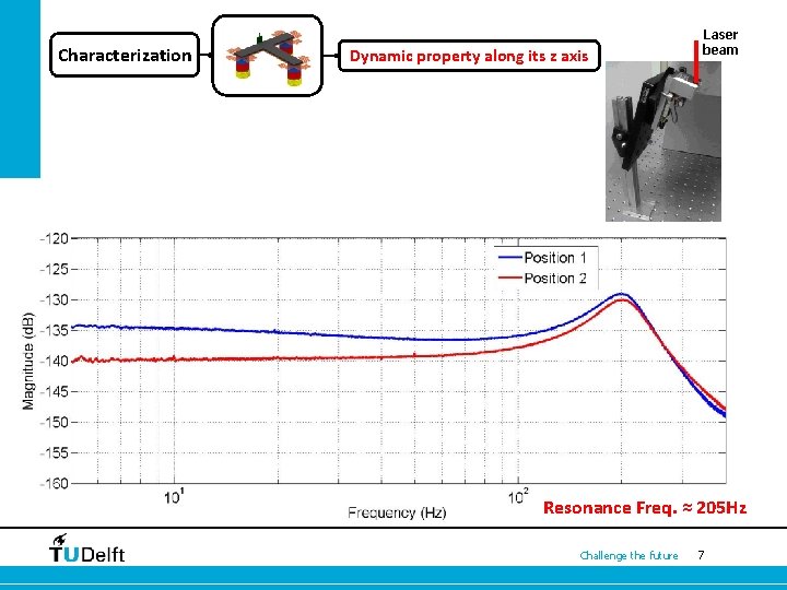
Characterization Dynamic property along its z axis Laser beam Resonance Freq. ≈ 205 Hz Challenge the future 7
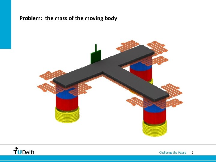
Problem: the mass of the moving body z Challenge the future 8
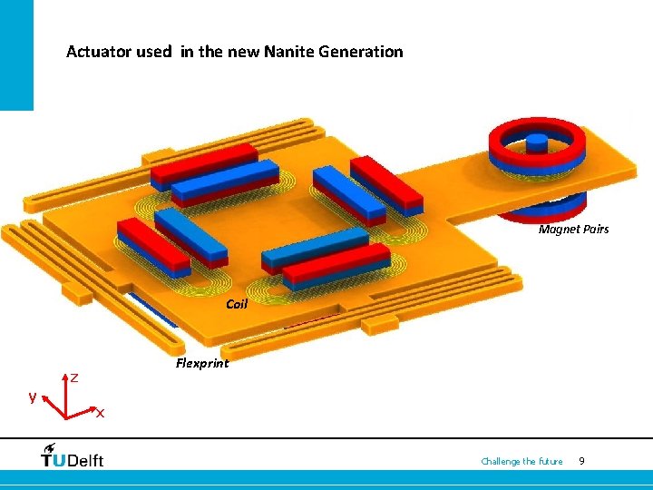
Actuator used in the new Nanite Generation Magnet Pairs Coil Flexprint z y x Challenge the future 9
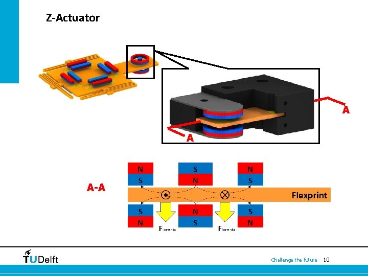
Z-Actuator A A A-A Challenge the future 10
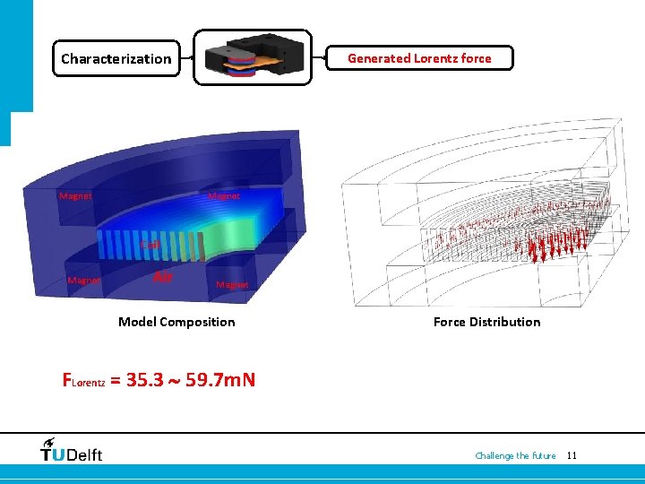
Characterization Model Composition Generated Lorentz force Force Distribution FLorentz = 35. 3 59. 7 m. N Challenge the future 11
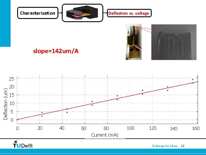
Characterization Deflection vs. voltage slope≈142 um/A Deflection (um) 25 20 15 10 5 0 0 20 40 60 80 Current (m. A) 100 120 160 140 Challenge the future 12
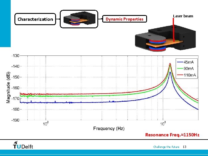
Characterization Dynamic Properties Laser beam Resonance Freq. ≈1150 Hz Challenge the future 13
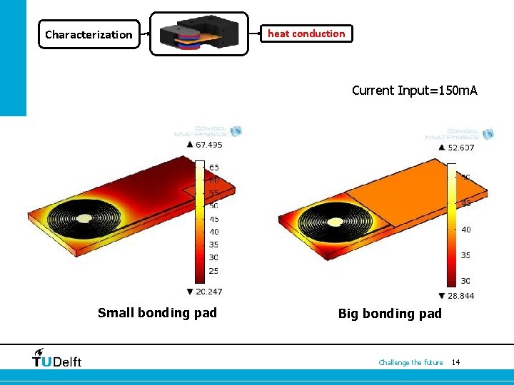
Characterization heat conduction Current Input=150 m. A Small bonding pad Big bonding pad Challenge the future 14
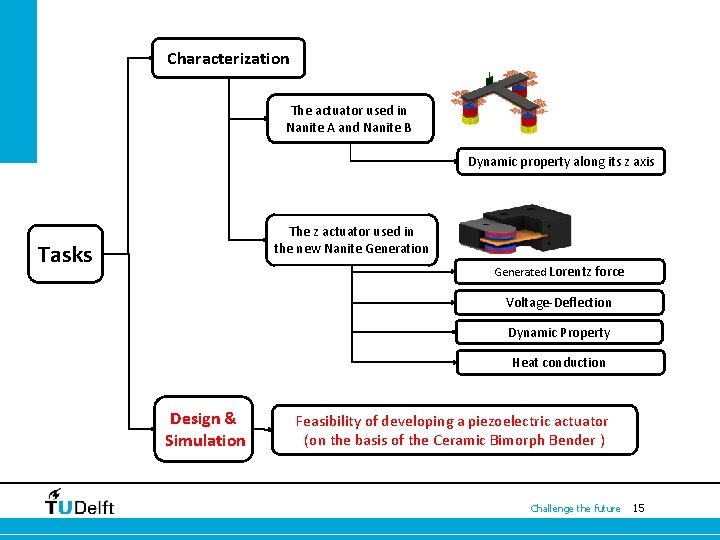
Characterization The actuator used in Nanite A and Nanite B Dynamic property along its z axis The z actuator used in the new Nanite Generation Tasks Generated Lorentz force Voltage-Deflection Dynamic Property Heat conduction Design & Simulation Feasibility of developing a piezoelectric actuator (on the basis of the Ceramic Bimorph Bender ) Challenge the future 15
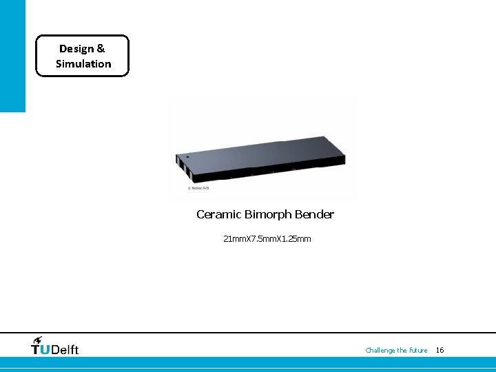
Design & Simulation Ceramic Bimorph Bender 21 mm. X 7. 5 mm. X 1. 25 mm Challenge the future 16
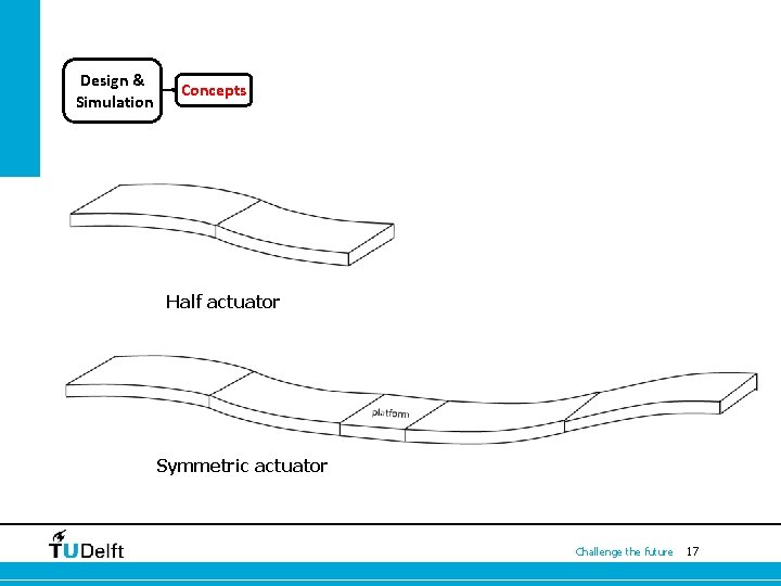
Design & Simulation Concepts Half actuator Symmetric actuator Challenge the future 17
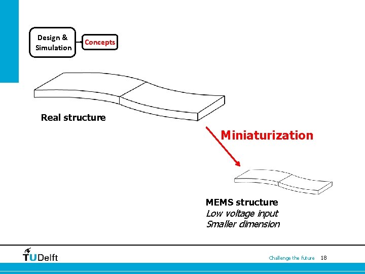
Design & Simulation Concepts Real structure Miniaturization MEMS structure Low voltage input Smaller dimension Challenge the future 18
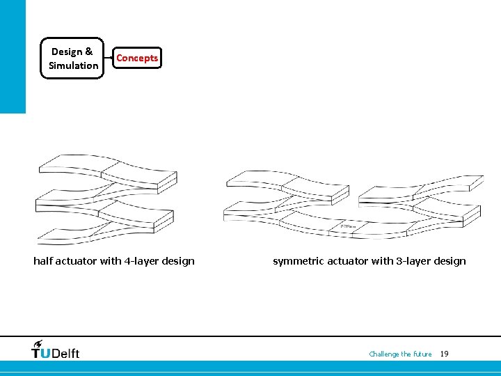
Design & Simulation Concepts half actuator with 4 -layer design symmetric actuator with 3 -layer design Challenge the future 19
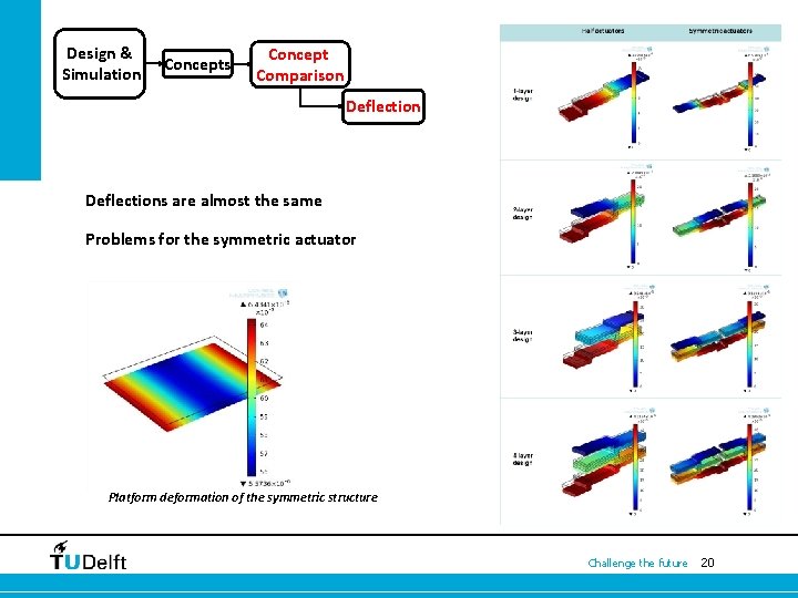
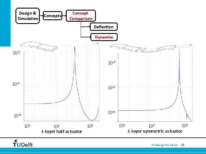
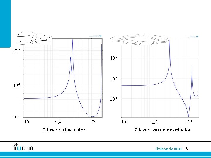
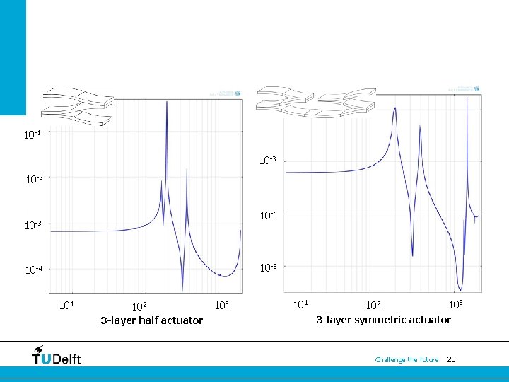
Design & Simulation Concepts Concept Comparison Deflections are almost the same Problems for the symmetric actuator Platform deformation of the symmetric structure Challenge the future 20
Design & Simulation Concepts Concept Comparison Deflection Dynamics 10 -2 10 -3 10 -4 101 102 1 -layer half actuator 103 101 102 103 1 -layer symmetric actuator Challenge the future 21
10 -2. 1 10 -2 10 -3 10 -4 101 102 2 -layer half actuator 103 101 102 103 2 -layer symmetric actuator Challenge the future 22
10 -1 10 -3 10 -2 10 -4 10 -3 10 -5 10 -4 101 102 3 -layer half actuator 103 101 102 103 3 -layer symmetric actuator Challenge the future 23
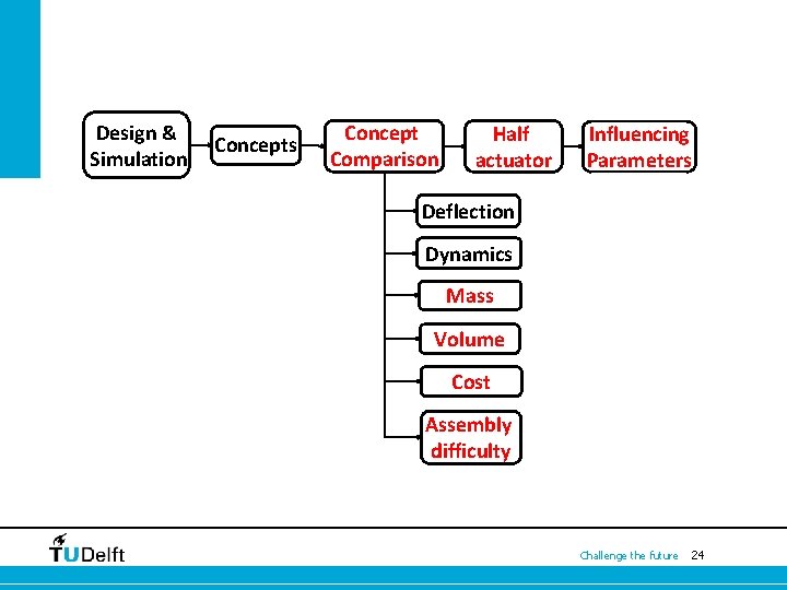
Design & Simulation Concepts Concept Comparison Half actuator Influencing Parameters Deflection Dynamics Mass Volume Cost Assembly difficulty Challenge the future 24
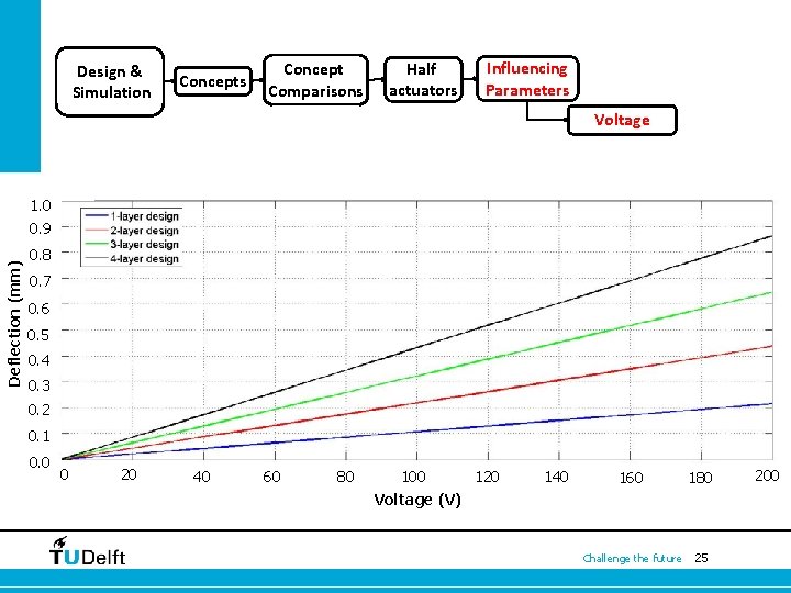
Design & Simulation Concepts Concept Comparisons Half actuators Influencing Parameters Voltage 1. 0 Deflection (mm) 0. 9 0. 8 0. 7 0. 6 0. 5 0. 4 0. 3 0. 2 0. 1 0. 0 0 20 40 60 80 100 120 Voltage (V) 140 160 180 Challenge the future 25 200
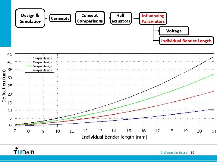
Design & Simulation Concept Comparisons Concepts Half actuators Influencing Parameters Voltage Individual Bender Length 45 Deflection (um) 40 35 30 25 20 15 10 5 0 7 8 9 10 11 12 13 14 15 16 17 18 19 20 Individual bender length (mm) Challenge the future 26 21
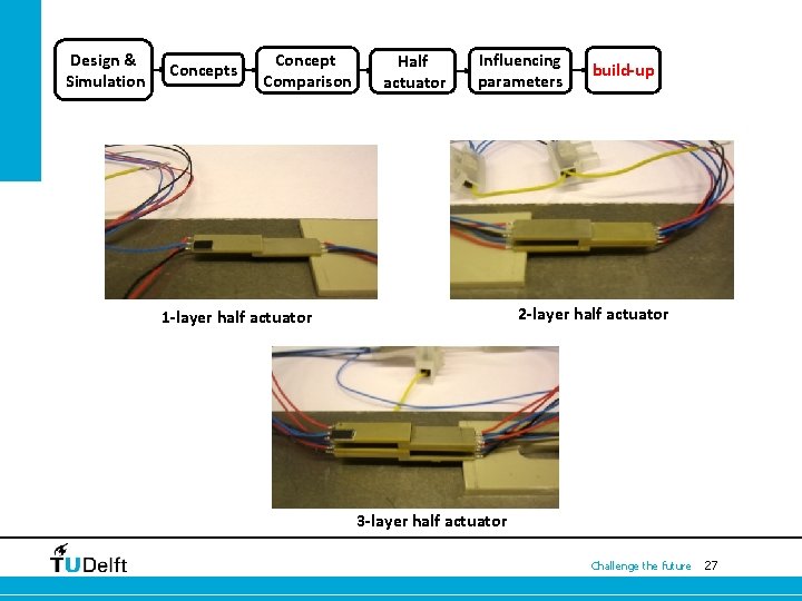
Design & Simulation Concepts Concept Comparison Half actuator Influencing parameters build-up 2 -layer half actuator 1 -layer half actuator 3 -layer half actuator Challenge the future 27
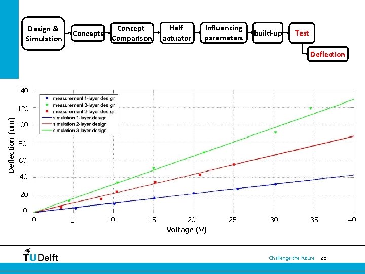
Design & Simulation Concepts Concept Comparison Half actuator Influencing parameters build-up Test Deflection 140 Deflection (um) 120 100 80 60 40 20 0 0 5 10 15 20 Voltage (V) 25 30 35 Challenge the future 40 28
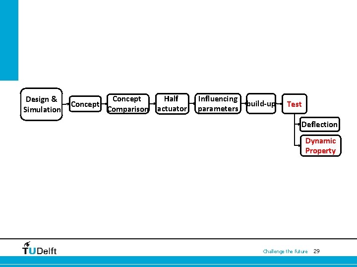
Design & Simulation Concept Half Concept Comparison actuator Influencing build-up parameters Test Deflection Dynamic Property Challenge the future 29
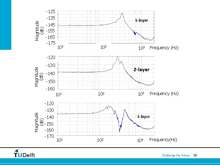
Magnitude (d. B) -125 -135 -145 -155 -165 -175 1 -layer 101 102 103 Frequency (Hz) Magnitude (d. B) -120 -130 2 -layer -140 -150 -160 Magnitude (d. B) 101 102 103 Frequency (Hz) -120 -130 -140 -150 -160 -170 3 -layer 101 102 103 Frequency(Hz) Challenge the future 30
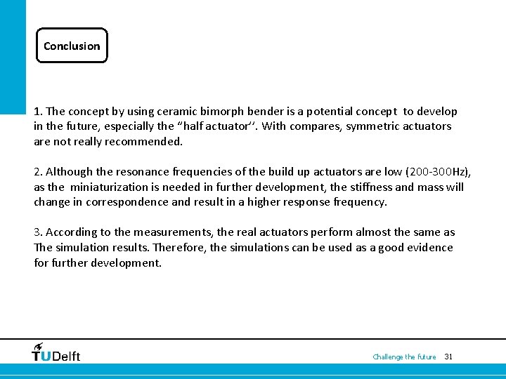
Conclusion 1. The concept by using ceramic bimorph bender is a potential concept to develop in the future, especially the ‘’half actuator’’. With compares, symmetric actuators are not really recommended. 2. Although the resonance frequencies of the build up actuators are low (200 -300 Hz), as the miniaturization is needed in further development, the stiffness and mass will change in correspondence and result in a higher response frequency. 3. According to the measurements, the real actuators perform almost the same as The simulation results. Therefore, the simulations can be used as a good evidence for further development. Challenge the future 31