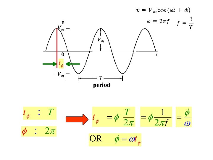
A sinusoidal current source independent or dependent produces
 produces a current That varies sinusoidally with")
 or rms as")

 should be a sinusoidal of frequency")


")


 Domain")


 Domain")
 Consider")


")


 Construct the frequency-domain")


 Since")


- Slides: 53
A sinusoidal current source (independent or dependent) produces a current That varies sinusoidally with time
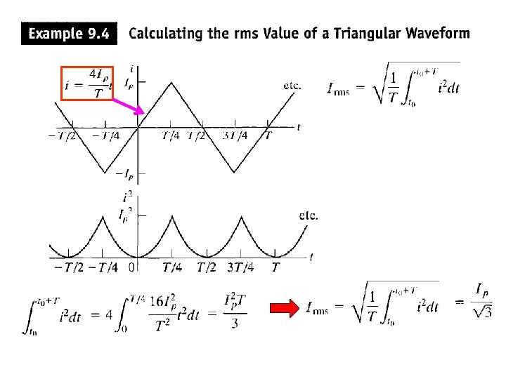
We define the Root Mean Square value of v(t) or rms as
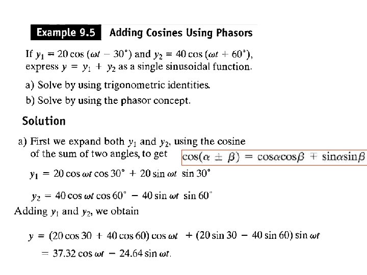
The Root Mean Square value of Expand using trigonometric identity
9. 2 The Sinusoidal Response Solution for i(t) should be a sinusoidal of frequency 3 We notice that only the amplitude and phase change In this chapter, we develop a technique for calculating the response directly without solving the differential equation
Time Domain Deferential Equation Complex Domain Algebraic Equation
9. 3 The phasor is a complex number that carries the amplitude and phase angle information of a sinusoidal function The phasor concept is rooted in Euler’s identity relates the complex exponential function to the trigonometric function We can think of the cosine function as the real part of the complex exponential and the sine function as the imaginary part Because we are going to use the cosine function on analyzing the sinusoidal steady-state we can apply
We can move the coefficient Vm inside The quantity is a complex number define to be the phasor that carries the amplitude and phase angle of a given sinusoidal function Phasor Transform Were the notation Is read “ the phasor transform of
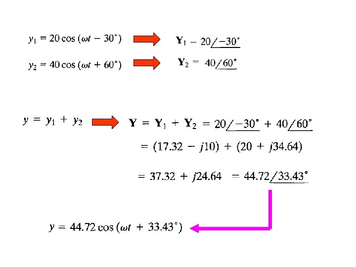
Summation Property of Phasor (can be shown)
Since Next we derive y using phsor method
The V-I Relationship for a Resistor Let the current through the resistor be a sinusoidal given as Is also sinusoidal with amplitude And phase The sinusoidal voltage and current in a resistor are in phase
Now let us see the pharos domain representation or pharos transform of the current and voltage Phasor Transform Which is Ohm’s law on the phasor ( or complex ) domain
The voltage and the current are in phase Imaginary Real
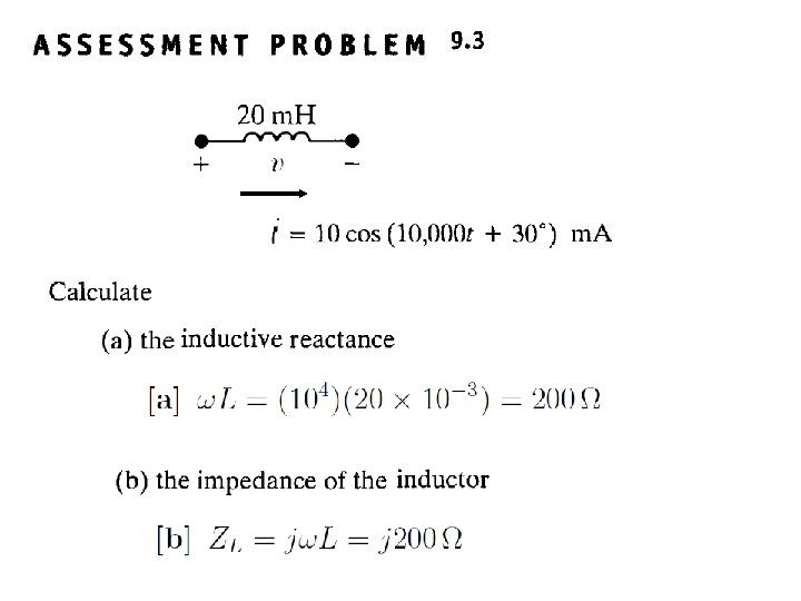
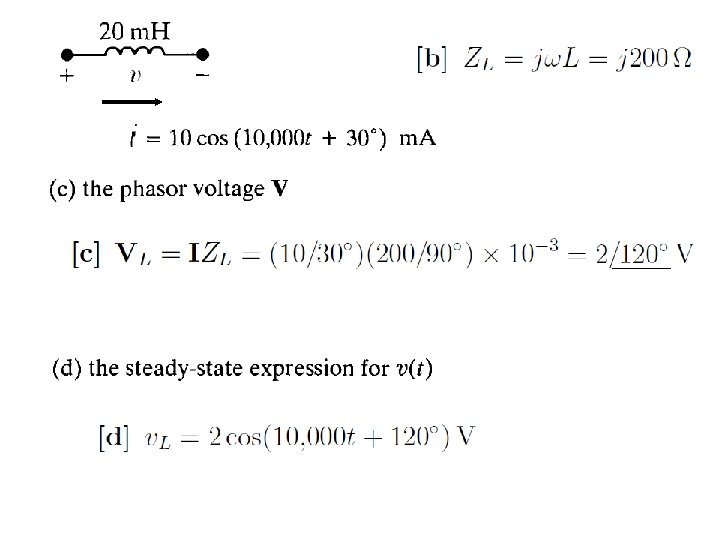
The V-I Relationship for an Inductor Let the current through the resistor be a sinusoidal given as The sinusoidal voltage and current in an inductor are out of phase by 90 o The voltage lead the current by 90 o or the current lagging the voltage by 90 o You can express the voltage leading the current by T/4 or 1/4 f seconds were T is the period and f is the frequency
Now we rewrite the sin function as a cosine function ( remember the phasor is defined in terms of a cosine function) The pharos representation or transform of the current and voltage But since Therefore and
and The voltage lead the current by 90 o or the current lagging the voltage by 90 o Imaginary Real
The V-I Relationship for a Capacitor Let the voltage across the capacitor be a sinusoidal given as The sinusoidal voltage and current in an inductor are out of phase by 90 o The voltage lag the current by 90 o or the current leading the voltage by 90 o
The V-I Relationship for a Capacitor The pharos representation or transform of the voltage and current and
and The voltage lag the current by 90 o or the current lead the voltage by 90 o Imaginary Real
Time-Domain Phasor ( Complex or Frequency) Domain
Impedance and Reactance The relation between the voltage and current on the phasor domain (complex or frequency) for the three elements R, L, and C we have When we compare the relation between the voltage and current , we note that they are all of form: Which the state that the phasor voltage is some complex constant ( Z ) times the phasor current This resemble ( ) ﺷﺒﻪ Ohm’s law were the complex constant ( Z ) is called “Impedance” ( )ﺃﻌﺎﻗﻪ Recall on Ohm’s law previously defined , the proportionality content R was real and called “Resistant” ( )ﻣﻘﺎﻭﻣﻪ Solving for ( Z ) we have The Impedance of a resistor is The Impedance of an indictor is The Impedance of a capacitor is In all cases the impedance is measured in Ohm’s W
Impedance The Impedance of a resistor is The Impedance of an indictor is In all cases the impedance is measured in Ohm’s W The Impedance of a capacitor is The imaginary part of the impedance is called “reactance” The reactance of a resistor is We note the “reactance” is associated with energy storage elements like the inductor and capacitor The reactance of an inductor is The reactance of a capacitor is Note that the impedance in general (exception is the resistor) is a function of frequency At w = 0 (DC), we have the following short open
Time Domain Phasor (Complex) Domain
9. 5 Kirchhoff’s Laws in the Frequency Domain ( Phasor or Complex Domain) Consider the following circuit Phasor Transformation KVL Using Euler Identity we have Which can be written as Factoring Phasor So in general Can not be zero KVL on the phasor domain
Kirchhoff’s Current Law A similar derivation applies to a set of sinusoidal current summing at a node Phasor Transformation KCL on the phasor domain
9. 6 Series, Parallel, Simplifications and Ohm’s law in the phosor domain
Example 9. 6 for the circuit shown below the source voltage is sinusoidal (a) Construct the frequency-domain (phasor, complex) equivalent circuit ? (b) Calculte the steady state current i(t) ? The source voltage pahsor transformation or equivalent The Impedance of the indictor is The Impedance of the capacitor is
To Calculate the phasor current I
and Ohm’s law in the phosor domain
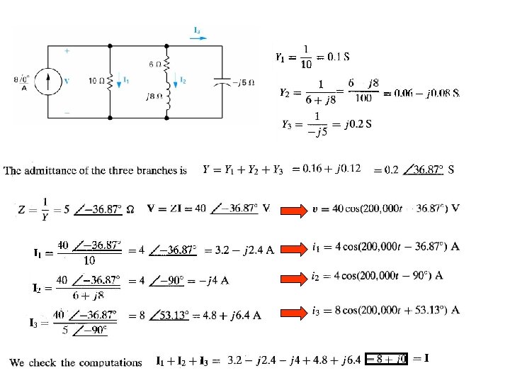
Example 9. 7 Combining Impedances in series and in Parallel (a) Construct the frequency-domain (phasor, complex) equivalent circuit ? (b) Find the steady state expressions for v, i 1, i 2, and i 3 ? ? (a)
Delta-to Wye Transformations D to Y Y to D
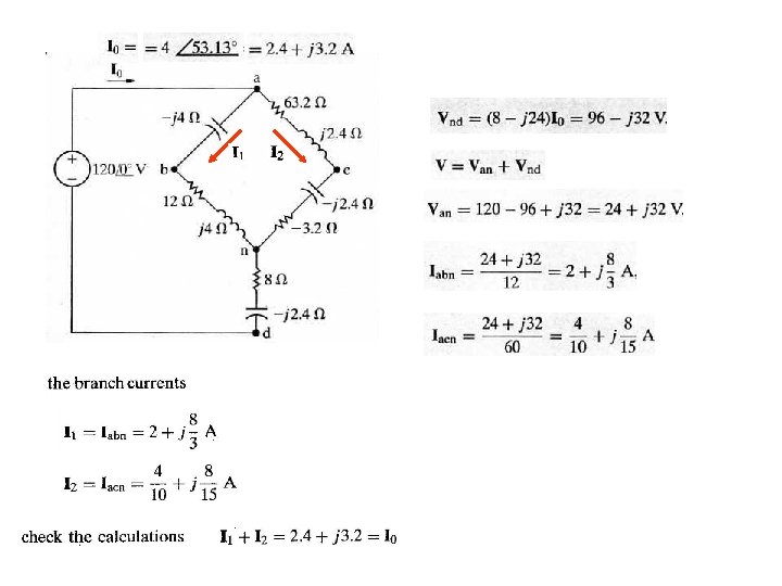
Example 9. 8
9. 7 Source Transformations and Thevenin-Norton Equivalent Circuits Source Transformations Thevenin-Norton Equivalent Circuits
Example 9. 9
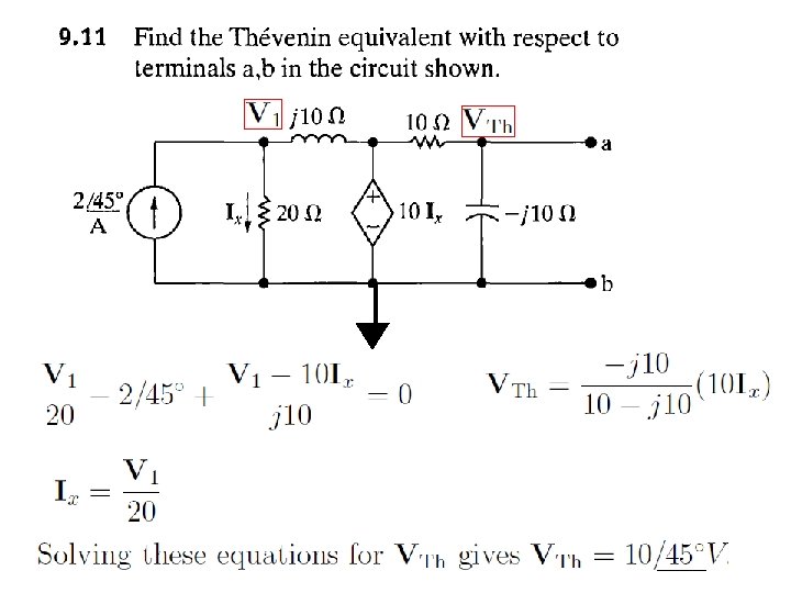
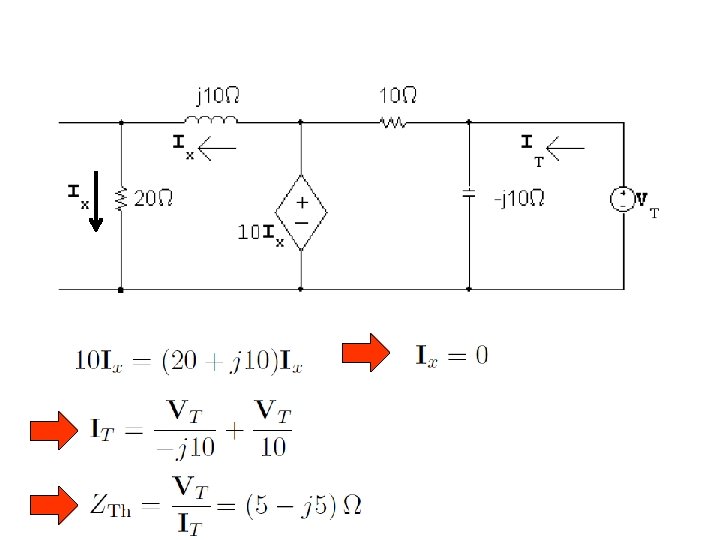
Example 9. 10 Source Transformation KVL Since then Next we find the Thevenin Impedance
Thevenin Impedance
9. 8 The Node-Voltage Method Example 9. 11 KCL at node 2 (1) Since (2) Two Equations and Two Unknown , solving
To Check the work
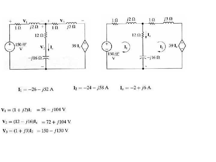
9. 9 The Mesh-Current Method Example 9. 12 KVL at mesh 1 KVL at mesh 2 Since (2) Two Equations and Two Unknown , solving (1)
9. 12 The Phasor Diagram