A proposed collider in China Chuang Zhang and


 ~100 participants from 9 countries A joint stage")


")
")
 9")
 Inverse Compton Scattering (ICS) high energy (2) H")


 Electron Wave Length( m) 1. 054 Energy(Me. V) 200")

 CAIN simulation Simulations with the code CAIN have been performed")
 19")
 Total cross section for light – light scattering s ( b) 1")
 Number of events per second 7 E-09 2 E-04 6 E-09 2")
 3. 2 Electron beam energy and laser power To increase electron energy")
 3. 3 CP-IP distance and Crossing angle Optimized CP-IP distance is around")
 Luminosity vs. crossing angle 1. 80 E+28 1. 60 E+28 Luminosity (cm-2")
 3. 4 Electron beam size at IP Reduction of electron bean size")


 35 80")
 4. 5 The FFS permanent magnets 2. 0 T vs.")
 Detector dimension Ø Length =76 cm Ø")

 Detection simulation Back to back photons 0. 0019")
 Detection simulation Low momentum e+ e- not back")
 Detection simulation Back to back e- e- 0.")


- Slides: 44
A proposed collider in China Chuang Zhang and Weiren Chou For the Bgg. C Study Group Photon Beam Workshop 2017 November 27 -28, Padova
Acknowledgement IHEP Huang Yongsheng, Zhang Chunlei, Lu Junguang, An Guangpeng, Chi Yunlong, Pei Shilun, Pei Guoxi, Zhang Jingru, Li Jingyi, Liu Weibin, Yuan Chen Tsinghua University Lu Wei, Du Yingchao Beihang University Shen Chengping, Sun Baohua Japan T. Takahashi, K. Yokoya, K. Homma Italy Luca Serafini, Vittoria Petrillo, Massimo Ferrario France Amplitude Technology USA Chris Barty, Bob Byer, A. Galvanauskas, Russell Wilcox , Mayda Velasco Russia V. Telnov 2
A proposed collider in China Introduction Scheme and site of Bgg. C Parameter optimization Design study on Bgg. C Summary
ICFA Mini-Workshop on Collider (April, TU) ~100 participants from 9 countries A joint stage of several scientific communities: HEP ( ) + NP ( -ray) + 4 accelerator + laser
Various Proposals for Photon Collider HFi. TT CLIC-based SAPPHi. RE X band-based 5
CEPC as a γγ Higgs Factory Goal: 10, 000 Higgs/year RF (650 MHz, 8 sets, 0. 5 GV /set) RF RF e‒ (80 Ge. V) Fiber Laser γγ collision (0. 351 μm, 5 J, 3 k. Hz) (125 Ge. V) e‒ (80 Ge. V) RF RF ster e‒ Boo V e 80 G E = 80 Ge. V ρ= 6000 m U = 0. 6 Ge. V/turn e‒ RF RF RF I = 48 m. A x 2 P(rf) = 58 MW 6
b (V. Telnov)
(M. Velasco)
I. Drebot et. al, PRAB 20, 043402 (2017) 9
Collider Principle Two steps: (1) Inverse Compton Scattering (ICS) high energy (2) H ( bb, cc, , , e+e- ) W. Chou Photon 2017, CERN 10
2. Scheme and site of Bgg. C Machine Candidates in China Institution Machine Energy IHEP BEPC linac 0. 18 – 2. 7 Ge. V HEPS linac 300 Me. V HEPS ring 6 Ge. V TTX 50 Me. V XGLS photoinjector 130 Me. V XGLS linac 400 Me. V Tsinghua U. USTC Hefei Light Source linac 800 Me. V Shanghai SSRF linac 150 Me. V SSRF ring 3. 5 Ge. V SXFEL linac 0. 8 – 1. 3 Ge. V HXFEL linac 8 Ge. V (red: under construction or approved for construction)
BEPC Ring, Linac and Hall #10 N S 12
Hall #10 – Present Layout W. Chou gg collider meeting, 8/23/2017 13
How to build a Collider in Hall #10 3. 8 m 2 e- pulses from BEPC Linac 200 Me. V, 2 x 2 n. C, 50 Hz e- Arc A B = 0. 6 T-m Arc B w Laser e- 14 m e- (1 μm, 2 J, 1 ps, 50 Hz) FFS e- γ γ e- FFS γγ collision (1 Me. V c. m. ) 35 m Two unique experiments: • scattering: predicted (Halpern) but never observed in the laboratory • e+e : predicted (Breit-Wheeler) but never observed in the laboratory W. Chou gg collider meeting, 10/25/2017 14
3. Parameters optimization Luminosity and event rate Electron beam energy & laser power CP-IP distance and crossing angle Electron beam size at IP Distance between FFS quad to IP
Preliminary Parameters Laser (T. Takahashi) Electron Wave Length( m) 1. 054 Energy(Me. V) 200 Size at focus RMS ( m) 5 Bunch charge(n. C) 2 Rayleigh Range( m) 298 Size at IP ( m) 2 Pulse energy (J) 2 Emittance (nm) 6. 39 Pulse Length( m) 300 (1 ps) b* ( m) 626 Repetition (Hz) 50 Bunch length (mm) 0. 6 Crossing angle(mrad) 167 Repetition (Hz) 50 IP-CP distance( m) 313 Crossing angle (mrad) 0 Nonlinear parameter a 0 0. 45 Geometric luminosity 1. 6 1028 cm-2 s-1 Event rate: • : L = 1 x 1027, = 3 b several events per hour (40, 000 events/ year) (Comparable to the Higgs rate in CEPC, in which the luminosity is higher by 7 orders of magnitude, but cross section is smaller by 7 orders of magnitude) • e+e : L = 1 x 1027, = 100 mb 100 events per second
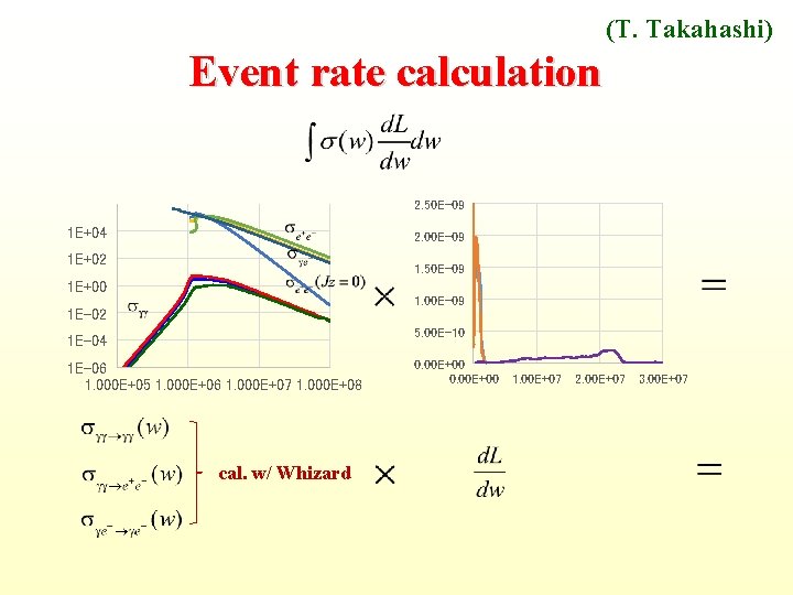
3. 1 Luminosity and event rate CAIN simulation Physics programs such as Whizard, Grace, Detector simulation
(T. Takahashi, Y. Huang) CAIN simulation Simulations with the code CAIN have been performed for ICS of electron – laser beams. Electron beams are with energy of 200 -300 Me. V, bunch charge of 2 p. C and length of 0. 6 mm. 200 The laser wave length is 1. 054 m, pulse energy 0. 5 -1 -2 J and size at focus 5 m. Crossing angle=0 -167 mrad, repetition frequency=50 Hz, IP-CP distance=100– 313 -1000 m. 167 313 Photon spectrum Luminosity spectrum
~E 6 e+e Edoardo Milotti (LNF-IRIDE) 19
(T. Takahashi) Total cross section for light – light scattering s ( b) 1 E+00 1 E-01 1 E-02 1 E-03 1 E-04 1 E-05 1 E-06 1 E+05 1 E+06 1 E+07 Ecm (e. V) 1 E+08
(T. Takahashi) Number of events per second 7 E-09 2 E-04 6 E-09 2 E-04 4 E-05 Jz=0 4 E-09 3 E-05 Jz=0 2 E-04 5 E-09 1 E-04 3 E-05 1 E-04 2 E-05 3 E-09 1 E-04 2 E-09 8 E-05 2 E-05 6 E-05 1 E-09 4 E-05 0 E+00 -1 E-09 0 E+00 5 E-06 2 E-05 5 E+05 1 E+06 2 E+06 0 E+00 5 E+05 1 E+06 2 E+06 The events are highly boosted, and do not enter detector volumes.
(Y. Huang) 3. 2 Electron beam energy and laser power To increase electron energy towards 300 Me. V helps luminosity and event rate Needs to consider how to identify with e+e- pairs and reduce background. Laser pulse energy: 2 J 1 J L 27% (almost same for 1 J 0. 5 J)
(Y. Huang) 3. 3 CP-IP distance and Crossing angle Optimized CP-IP distance is around 400 m. The smaller the laser-beam crossing angle, the higher luminosity Choice of L* + design of FFS quadrupole + using deflection mirrors
(T. Takahashi) Luminosity vs. crossing angle 1. 80 E+28 1. 60 E+28 Luminosity (cm-2 s-1) 1. 40 E+28 Total 1. 20 E+28 167 mrad 1. 00 E+28 8. 00 E+27 6. 00 E+27 E > 0. 9 Me. V 4. 00 E+27 2. 00 E+27 0. 00 E+00 0. 05 0. 10 0. 15 0. 20 Crossing angle (rad) (for ex. 0. 1 rad means 1 cm offset at the magnet surface placed 10 cm from the IP)
(T. Takahashi) 3. 4 Electron beam size at IP Reduction of electron bean size at IP helps luminosity. Need to be optimized together with FFS design. 1. 80 E+28 Luminosity (cm-2 s-1) 1. 60 E+28 sx, y=2 m 1. 40 E+28 1. 20 E+28 Total 1. 00 E+28 8. 00 E+27 E > 0. 9 Me. V 6. 00 E+27 4. 00 E+27 2. 00 E+27 0. 00 E+00 0 1 2 3 4 Electron beam size sx, y (mm) 5 6
3. 5 Distance between FFS quad to IP The distance between FFS quad to IP is chosen as 10 cm for study. Needs to be optimized together with crossing angle and FFS design.
4. Design study on Bgg. C Photocathode RF gun 200 Me. V electron linac Electron beam transfer line Laser system FFS permanent quadrupoles Detector
4. 1 Photocathode RF gun Y. C. Du
4. 2 200 Me. V electron linac No space at this location! S. Pei Possible injection point for the photoinjector beam!
S. Pei The possible linac layout for the collider K 16 K 15 K B 1 A RF GUN Photoinjector beam AM 3 A 54 A 53 A 52 A 51 A 50 A 49 A 48 A 47 B 2 A 46 Linac beam The last section of BEPCII linac 1 photocathode RF gun 1 accelerating structure 1 klystron 2 bending magnets The existing linac 1 laser system 1 solenoid new compact triplet ……
4. 3 Electron beam transfer line Arc A mx 1=0. 384 p Dmx=p LQ=0. 1 m mx 1=1. 384 p LB=1. 0 m Dx= 0. 0 m
Arc B mx 1=0. 324 p Dmx=2 p LQ=0. 1 m mx 1=2. 324 p LB=1. 0 m Dx = 0. 0 m
Match from linac and to FFS To match Twiss parameters to the arcs and design a kicker / septum system to extract the leading bunch to the Arc B. To match Twiss parameters from the end of Arc A and Arc B to the IR; To design the final focusing system. Kicker Match to Arc B Septum Match to FFS Match to Arc A Match to FFS
4. 4 Laser system Refer to HAPLS (ELI-E 23) 35 80
(Y. Huang, Y. Chen) 4. 5 The FFS permanent magnets 2. 0 T vs. 1. 95 T @ 3 mm 36 80
4. 5 Detector (Y. Huang, J. Lu) Detector dimension Ø Length =76 cm Ø Inner diameter = 40 cm Ø Thickness = 6 cm PS detector Ø Attached in front and inner side of the crystal Ø Thickness = 1 cm. Cs. I cristal Ø 46 Lines, Ø 23 crystals per line Ø 966 crystals
Detector simulation Detection simulations design, resolution, efficiency, background Physics simulation γγ γγ, γγ e+e-, γe- Shielding design and simulation beam Scattering, collimation design The study gets under way
(T. Takahashi & B. H. Sun) Detection simulation Back to back photons 0. 0019 events/s
(T. Takahashi & B. H. Sun) Detection simulation Low momentum e+ e- not back to back 64 events/s
(T. Takahashi & B. H. Sun) Detection simulation Back to back e- e- 0. 5 events/s
Stand-alone - Collider 2 e- pulses 200 Me. V, 50 Hz 3. 8 m RF GUN A 0 A 1 14 m e. A 2 A 3 A 4 w =3 m 14 m e. B = 2 – 3 k. G K 1 K 2 K 3 e- Laser 35 m (1 μm, 2 J, 50 Hz) FFS e- γ γ e- FFS γγ collision (1 Me. V) e-
Summary A collider based on the BEPC injector proposed; is The luminosity goal is 1 1027 cm-2 s-1 for the center mass energy above 0. 9 Me. V. About 1 event/hour and 60 events/s are expected for and e+e- respectively. The parameter optimization has been performed. The design study for the project is in progress. The detector simulation is underway. The interesting physics and challenging project call for collaboration.
Thank You for Attention