A PROJECT ON PASSWORD BASED CONTROL SYSTEM CONTENTS


A PROJECT ON PASSWORD BASED CONTROL SYSTEM

CONTENTS • Main Objective • Kit Components Explanation • Block Diagram • Working Procedure • Advantages • Applications • Conclusion and Future scope • References

HARDWARE REQUIREMENTS: 8051 series Microcontroller, Relay Driver IC, Relays, Matrix Keypad, Crystal, Resistors, Capacitors, Diodes, LED, Transformer, Voltage Regulator, Lamps.

SOFTWARE REQUIREMENTS: Keil compiler Language: Embedded C or Assembly

Power supply We used for this as a adapter.

Description of power supply • The circuit uses standard power supply comprising of a step-down transformer from 230 v to 12 v and 4 diodes forming a Bridge Rectifier that delivers pulsating dc which is then filtered by an electrolytic capacitor of about 470 microf to 100 micro. F. • The filtered dc being un regulated IC LM 7805 is used to get 5 v constant at its pin no 3 irrespective of input dc varying from 9 v to 14 v. • The regulated 5 volts dc is further filtered by a small electrolytic capacitor of 10 micro f for any noise so generated by the circuit. • One LED is connected of this 5 v point in series with a resistor of 330 ohms to the ground i. e. negative voltage to indicate 5 v power supply availability.

MICROCONTROLLER: • AT 89 S 51 • It is a smaller computer • Has on-chip RAM, ROM, I/O ports. . . CP U I/O Port RAM RO M Serial Timer COM Port A single chip Microcontroller

Features of AT 89 S 51/52: Ø Compatible with MCS®-51 Products Ø 8 K Bytes of In-System Programmable (ISP) Flash Memory Ø Endurance: 10, 000 Write/Erase Cycles Ø 4. 0 V to 5. 5 V Operating Range Ø Fully Static Operation: 0 Hz to 33 MHz Ø 256 x 8 -bit Internal RAM Ø 32 Programmable I/O Lines Ø Three 16 -bit Timer/Counters Ø Full Duplex UART Serial Channel Ø Interrupt Recovery from Power-down Mode Ø Watchdog Timer Ø Dual Data Pointer

PIN DIAGRAM OF AT 89 S 51: • 40 Pin IC • 4 Ports • 32 Programmable I/O Lines

Special Microcontroller Features: • 100, 000 erase/write cycle Enhanced Flash program memory typical. • 1, 000 erase/write cycle Data EEPROM memory typical. • Data EEPROM Retention > 40 years. • Self-reprogrammable under software control. • In-Circuit Serial Programming™ (ICSP™) via two pins. • Single-supply 5 V In-Circuit Serial Programming. • Watchdog Timer (WDT) with its own on-chip RC oscillator for reliable operation. • Programmable code protection. • Power saving Sleep mode. • Selectable oscillator options. • In-Circuit Debug (ICD) via two pins.

Peripheral Features: • Timer 0: 8 -bit timer/counter with 8 -bit prescaler. • Timer 1: 16 -bit timer/counter with prescaler, can be incremented during Sleep via external crystal/clock. • Timer 2: 8 -bit timer/counter with 8 -bit period register, prescaler and postscaler. • Two Capture, Compare, PWM modules • - Capture is 16 -bit, max. resolution is 12. 5 ns • - Compare is 16 -bit, max. resolution is 200 ns • - PWM max resolution is 10 -bit • Synchronous Serial Port (SSP) with SPI™ (Master mode) and I 2 C™ (Master/Slave). • Universal Synchronous Asynchronous Receiver Transmitter (USART/SCI) with 9 -bit address detection. • Parallel Slave Port (PSP) – 8 bits wide with external RD, WR and CS controls (40/44 pin only). • Brown-out detection circuitry for Brown-out Reset (BOR).

MAIN OBJECTIVE • The project is designed to trip the circuit with the help of a password. • This control system provides a solution , which can ensure the safety of line man. • The system is fully controlled by the 8052 microcontroller (where password is saved initially)and by an IC.

Hardware Requirements • Transformer • Bridge Rectifier • Voltage Regulator • Micro Controller • EEPROM • TRIAC • Keypad • LCD screen

TRANSFORMER STEP UP TRANSFORMER STEP DOWN TRANSFORMER

BRIDGE RECTIFIER

VOLTAGE REGULATOR • A voltage regulator is an electrical regulator designed to automatically maintain a constant voltage level.

MICROCONTROLLER

PIN DIAGRAM OF 8052

TRIAC • The TRIAC is a three terminal semiconductor device for controlling current. • It is effectively a development of the SCR or thyristor, but unlike thyristor which is only able to conduct in one direction, the TRIAC is a bidirectional device.

KEYPAD • Keypads are the most widely used input devices of the 8052 and a basic understanding of them is essential. The keypads are mainly three types: 1) 4*3 keypad 2) 4*4 keypad 3) 4*8 keypad. • The keypad used in this project is 4*3 keypad.
 • Most common LCDs connected to the microcontrollers are 16")
LIQUID CRYSTAL DISPLAY (LCD) • Most common LCDs connected to the microcontrollers are 16 x 2 and 20 x 2 displays. • This means 16 characters per line by 2 lines and 20 characters per line by 2 lines, respectively. • The standard is referred to as HD 44780 U, which refers to the controller chip which receives data from an external source (and communicates directly with the LCD.

LCD BACKGROUND ØIf an 8 -bit data bus is used the LCD will require 11 data lines (3 control lines plus the 8 lines for the data bus) ØThe three control lines are referred to as EN, RS, and RW ØEN=Enable (used to tell the LCD that you are sending it data) ØRS=Register Select (When RS is low (0), data is treated as a command) (When RS is High(1), data being sent is text data ) ØR/W=Read/Write (When RW is low (0), the data written to the LCD) (When RW is low (0), the data reading to the LCD)

LCD DISPLAY • • LCDs are the most widely used output devices of the 8052. LCD stands for Liquid Crystal Display. LCD is finding wide spread use replacing LEDs. They are used for writing different messages on a miniature LCD.

BLOCK DIAGRAM

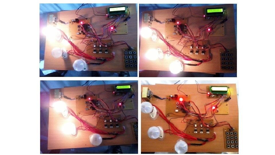
KIT DESCRIPTION & REPRESENTATION

q. ADVANTAGES ü ü It avoids the electrical accidents. Improves lineman safety. Easy of operation. Easy to maintain and repair. q APPLICATIONS ü Can be used any where in the substation to trip the circuit. ü Most useful to operate in the public areas.

CONCLUSION • Security is prime concern in our day-to-day life. Every one wants to be as much as secure as to be possible. • This system provides a new approach to secure the life of a lineman. • The circuit can be tripped without any fail and load can also be controlled when required.

FUTURE SCOPE • The project can be interfaced with the GSM modem for the remote control of circuit breaker via SMS. So the circuit breaker can, not only operate from the substation, but also from distance through wireless communication. • SCADA can also be implemented to know where the fault is occurred in the system directly and so a linemen can directly locate the fault location and can rectify it.


Y N A U Q ? S E I ER
- Slides: 32