
A possible linearizer at F 35 982 GHz
A possible linearizer at F = 35. 982 GHz for the Compact light XLS project presented by B. Spataro on behalf of Compact Light XLS project collaboration 4 th. EAAC workshop La Biodola Elba September 15 -21 2019
Summary Hard Edge cavity design Analytical and numerical comparison of the group velocity (hard edge shape) Rounded cavity design Longitudinal and transverse loss parameters estimations Accelerating electric field estimation Pulse heating and modified vector Poynting estimations Thermal stress studies Preliminary studies on the Electron gun for a Ka-Band klystron 4 th. EAAC workshop La Biodola Elba September 15 -21 2019
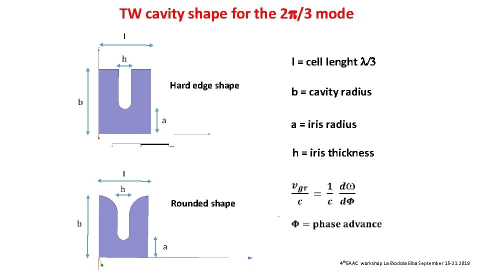
TW cavity shape for the 2 /3 mode I l = cell lenght l/3 Hard edge shape b = cavity radius a = iris radius h = iris thickness I Rounded shape 4 th. EAAC workshop La Biodola Elba September 15 -21 2019
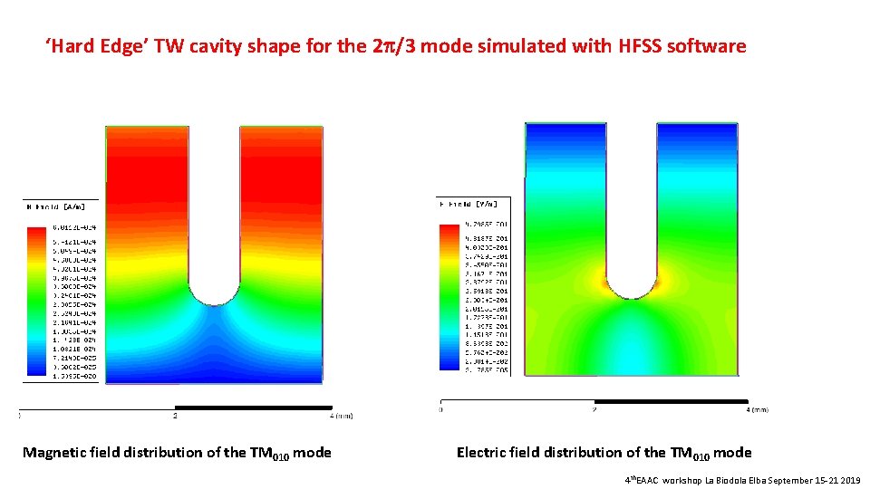
‘Hard Edge’ TW cavity shape for the 2 /3 mode simulated with HFSS software Magnetic field distribution of the TM 010 mode Electric field distribution of the TM 010 mode 4 th. EAAC workshop La Biodola Elba September 15 -21 2019
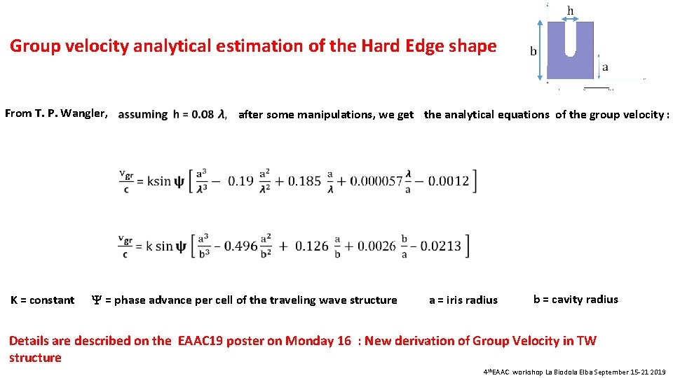
Group velocity analytical estimation of the Hard Edge shape From T. P. Wangler, after some manipulations, we get the analytical equations of the group velocity : K = constant = phase advance per cell of the traveling wave structure a = iris radius b = cavity radius Details are described on the EAAC 19 poster on Monday 16 : New derivation of Group Velocity in TW structure 4 th. EAAC workshop La Biodola Elba September 15 -21 2019
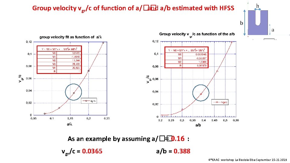
Group velocity vgr/c of function of a/�� and a/b estimated with HFSS As an example by assuming a/�� = 0. 16 : vgr/c = 0. 0365 a/b = 0. 388 4 th. EAAC workshop La Biodola Elba September 15 -21 2019
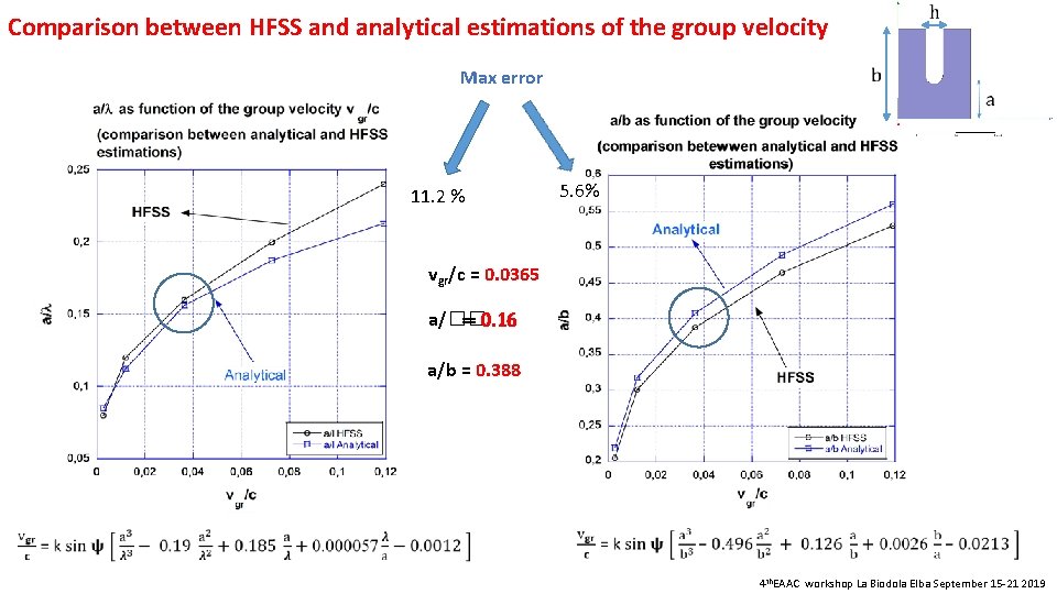
Comparison between HFSS and analytical estimations of the group velocity Max error 11. 2 % 5. 6% vgr/c = 0. 0365 a/�� = 0. 16 a/b = 0. 388 4 th. EAAC workshop La Biodola Elba September 15 -21 2019
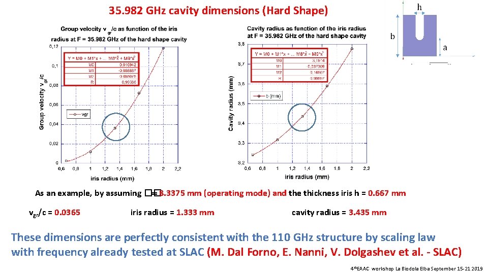
35. 982 GHz cavity dimensions (Hard Shape) As an example, by assuming �� = 8. 3375 mm (operating mode) and the thickness iris h = 0. 667 mm vgr /c = 0. 0365 iris radius = 1. 333 mm cavity radius = 3. 435 mm These dimensions are perfectly consistent with the 110 GHz structure by scaling law with frequency already tested at SLAC (M. Dal Forno, E. Nanni, V. Dolgashev et al. - SLAC) 4 th. EAAC workshop La Biodola Elba September 15 -21 2019
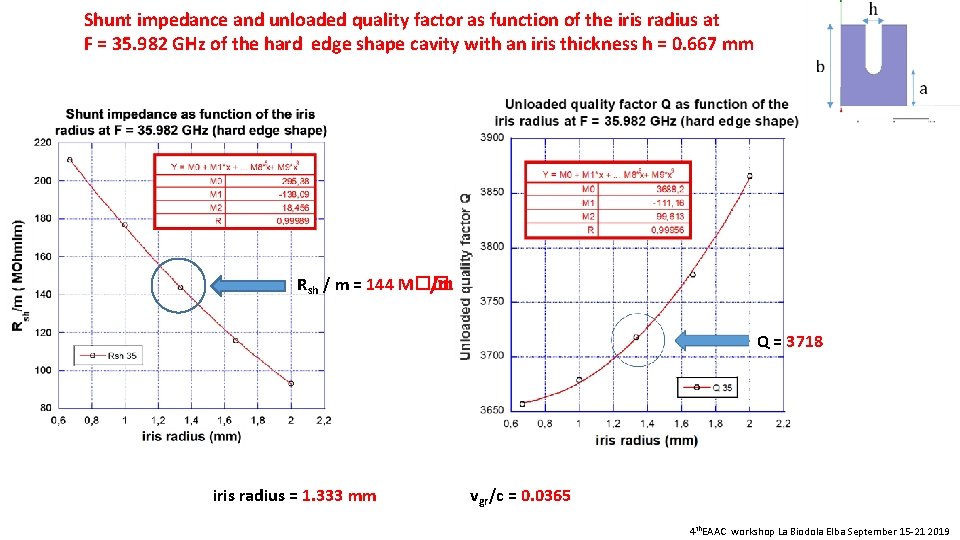
Shunt impedance and unloaded quality factor as function of the iris radius at F = 35. 982 GHz of the hard edge shape cavity with an iris thickness h = 0. 667 mm Rsh / m = 144 M�� /m Q = 3718 iris radius = 1. 333 mm vgr/c = 0. 0365 4 th. EAAC workshop La Biodola Elba September 15 -21 2019
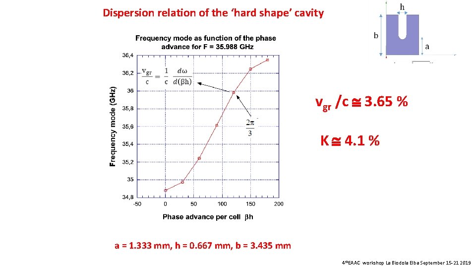
Dispersion relation of the ‘hard shape’ cavity vgr /c 3. 65 % K 4. 1 % a = 1. 333 mm, h = 0. 667 mm, b = 3. 435 mm 4 th. EAAC workshop La Biodola Elba September 15 -21 2019
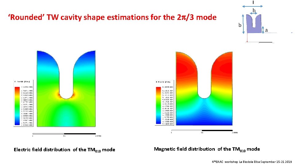
I ‘Rounded’ TW cavity shape estimations for the 2 /3 mode Electric field distribution of the TM 010 mode Magnetic field distribution of the TM 010 mode 4 th. EAAC workshop La Biodola Elba September 15 -21 2019
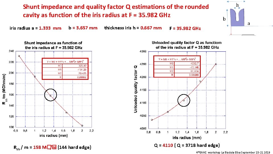
Shunt impedance and quality factor Q estimations of the rounded cavity as function of the iris radius at F = 35. 982 GHz iris radius a = 1. 333 mm b = 3. 657 mm Rsh / m = 158 M�� /m (144 hard edge) thickness iris h = 0. 667 mm F = 35. 982 GHz Q = 4110 ( Q = 3718 hard edge) 4 th. EAAC workshop La Biodola Elba September 15 -21 2019
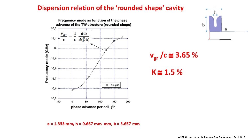
Dispersion relation of the ‘rounded shape’ cavity vgr /c 3. 65 % K 1. 5 % a = 1. 333 mm, h = 0. 667 mm mm, b = 3. 657 mm 4 th. EAAC workshop La Biodola Elba September 15 -21 2019
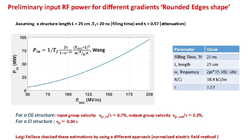
Preliminary input RF power for different gradients ‘Rounded Edges shape’ Assuming a structure length L = 25 cm , Tf = 20 ns (filling time) and = 0. 57 (attenuation) Parameter Value Filling Time, Tf 20 ns L, length 25 cm w, frequency 2 pi*35. 982 GHz R/Q 38. 4 kΩ/m 0. 57 For a CG structure: input group velocity vgr_in/c ~ 6. 7%, output group velocity vgr_out/c ~ 2. 2%, For a CI structure : vgr ~ 0. 04 c Luigi Faillace checked these estimations by using a different approach (normalized electric field method )
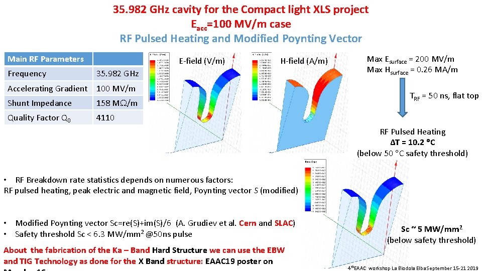
35. 982 GHz cavity for the Compact light XLS project Eacc=100 MV/m case RF Pulsed Heating and Modified Poynting Vector Main RF Parameters Frequency E-field (V/m) H-field (A/m) 35. 982 GHz Accelerating Gradient 100 MV/m Shunt Impedance 158 M /m Quality Factor Q 0 4110 Max Esurface = 200 MV/m Max Hsurface = 0. 26 MA/m TRF = 50 ns, flat top RF Pulsed Heating ΔT = 10. 2 C (below 50 C safety threshold) • RF Breakdown rate statistics depends on numerous factors: RF pulsed heating, peak electric and magnetic field, Poynting vector S (modified) • Modified Poynting vector Sc=re(S)+im(S)/6 (A. Grudiev et al. Cern and SLAC) • Safety threshold Sc < 6. 3 MW/mm 2 @50 ns pulse About the fabrication of the Ka – Band Hard Structure we can use the EBW and TIG Technology as done for the X Band structure: EAAC 19 poster on Sc ~ 5 MW/mm 2 (below safety threshold) 4 th. EAAC workshop La Biodola Elba September 15 -21 2019
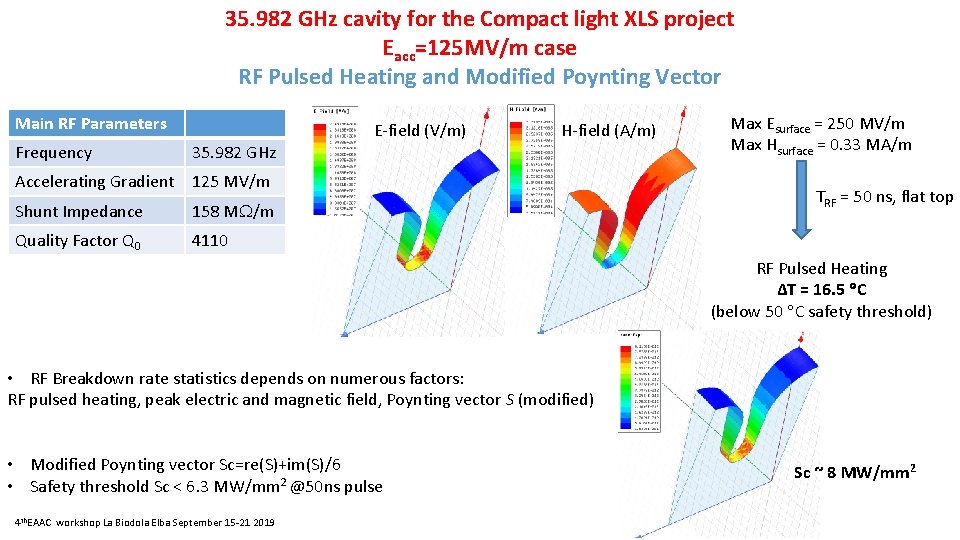
35. 982 GHz cavity for the Compact light XLS project Eacc=125 MV/m case RF Pulsed Heating and Modified Poynting Vector Main RF Parameters Frequency E-field (V/m) H-field (A/m) 35. 982 GHz Accelerating Gradient 125 MV/m Shunt Impedance 158 M /m Quality Factor Q 0 4110 Max Esurface = 250 MV/m Max Hsurface = 0. 33 MA/m TRF = 50 ns, flat top RF Pulsed Heating ΔT = 16. 5 C (below 50 C safety threshold) • RF Breakdown rate statistics depends on numerous factors: RF pulsed heating, peak electric and magnetic field, Poynting vector S (modified) • Modified Poynting vector Sc=re(S)+im(S)/6 • Safety threshold Sc < 6. 3 MW/mm 2 @50 ns pulse 4 th. EAAC workshop La Biodola Elba September 15 -21 2019 Sc ~ 8 MW/mm 2
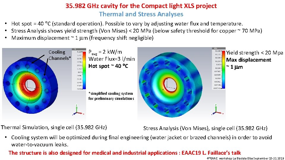
35. 982 GHz cavity for the Compact light XLS project Thermal and Stress Analyses • Hot spot = 40 C (standard operation). Possible to vary by adjusting water flux and temperature. • Stress Analysis shows yield strength (Von Mises) < 20 MPa (below safety threshold for copper ~ 70 MPa) • Maximum displacement ~ 1 m (frequency shift negligible) Cooling Channels* Pavg = 2 k. W/m Water Flux=3 l/min Hot spot ~ 40 C Yield strength < 20 Mpa Max displacement ~ 1 m *simplified cooling system for preliminary simulations Thermal Simulation, single cell (35. 982 GHz) Stress Analysis (Von Mises), single cell (35. 982 GHz) • Cooling system will be optimized during final engineering (water jacket or brazed channels) in order to avoid water-to-vacuum leaks. The structure is also designed for medical and industrial applications : EAAC 19 L. Faillace’s talk 4 th. EAAC workshop La Biodola Elba September 15 -21 2019
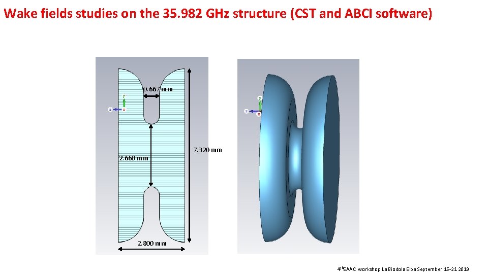
Wake fields studies on the 35. 982 GHz structure (CST and ABCI software) 0. 667 mm 2. 660 mm 7. 320 mm 2. 800 mm 4 th. EAAC workshop La Biodola Elba September 15 -21 2019
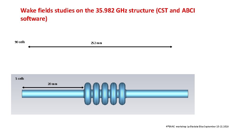
Wake fields studies on the 35. 982 GHz structure (CST and ABCI software) 90 cells 252 mm 5 cells 20 mm 4 th. EAAC workshop La Biodola Elba September 15 -21 2019

Wake fields studies on the 35. 982 GHz structure [�� (rms) : 1 mm] By assuming N = 90 cells (L= 252 mm), Kl = 320 V/p. C, Q = 100 p. C E ~ 32 Ke. V 4 th. EAAC workshop La Biodola Elba September 15 -21 2019
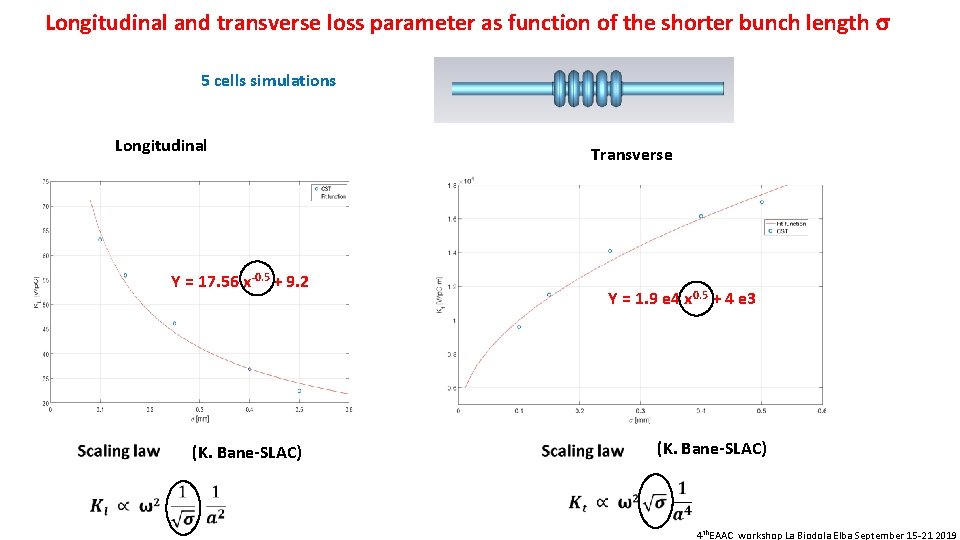
Longitudinal and transverse loss parameter as function of the shorter bunch length 5 cells simulations Longitudinal Transverse Y = 17. 56 x-0. 5 + 9. 2 Y = 1. 9 e 4 x 0. 5 + 4 e 3 (K. Bane-SLAC) 4 th. EAAC workshop La Biodola Elba September 15 -21 2019
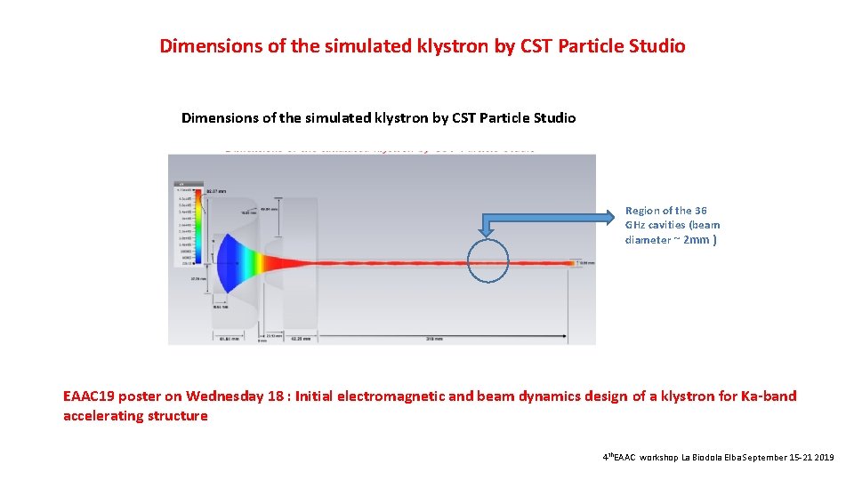
Dimensions of the simulated klystron by CST Particle Studio Region of the 36 GHz cavities (beam diameter ~ 2 mm ) EAAC 19 poster on Wednesday 18 : Initial electromagnetic and beam dynamics design of a klystron for Ka-band accelerating structure 4 th. EAAC workshop La Biodola Elba September 15 -21 2019
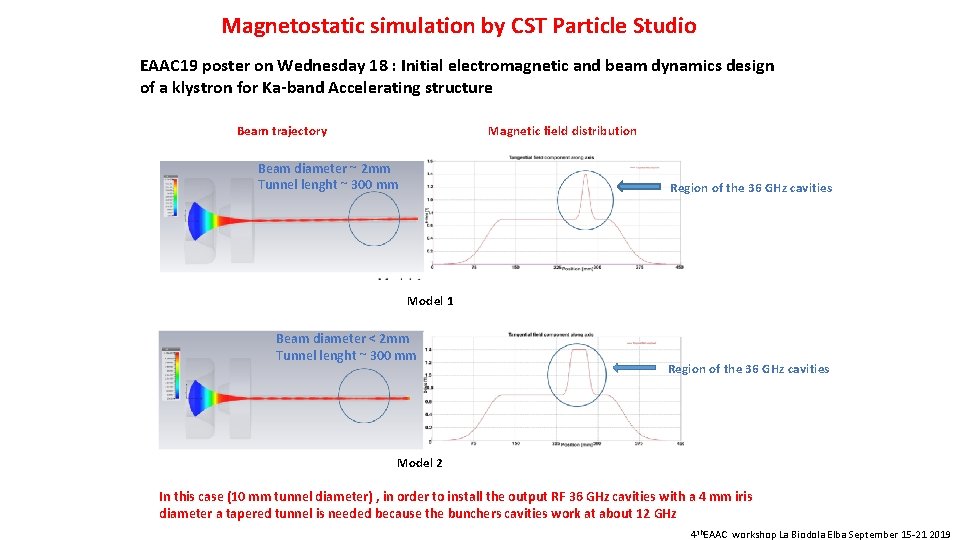
Magnetostatic simulation by CST Particle Studio EAAC 19 poster on Wednesday 18 : Initial electromagnetic and beam dynamics design of a klystron for Ka-band Accelerating structure Magnetic field distribution Beam trajectory Beam diameter ~ 2 mm Tunnel lenght ~ 300 mm Region of the 36 GHz cavities Model 1 Beam diameter < 2 mm Tunnel lenght ~ 300 mm Region of the 36 GHz cavities Model 2 In this case (10 mm tunnel diameter) , in order to install the output RF 36 GHz cavities with a 4 mm iris diameter a tapered tunnel is needed because the bunchers cavities work at about 12 GHz 4 th. EAAC workshop La Biodola Elba September 15 -21 2019
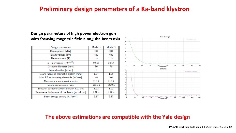
Preliminary design parameters of a Ka-band klystron Design parameters of high power electron gun with focusing magnetic field along the beam axis The above estimations are compatible with the Yale design 4 th. EAAC workshop La Biodola Elba September 15 -21 2019

Thanks a lot for your attention !
- Slides: 25