A LargeScale Parallel Computing of Boiling TwoPhase Flow

A Large-Scale Parallel Computing of Boiling Two-Phase Flow Behavior in Advanced Light-Water Reactors K. Takase, H. Yoshida, T. Misawa Thermal & Fluid Engineering Group Japan Atomic Energy Agency VECPAR 2008 Toulouse, France, 24 -27, June 2008

Objectives To establish a new thermal design procedure of nuclear reactors with large-scale numerical simulations; To attain the design by analysis; To simulate precisely two-phase flow characteristics in fuel bundles; and, To clarify physical mechanisms on boiling transition, two-phase turbulent structure, etc.
 drier separator core 18 m JAEA is now developing")
Reduced-Moderation Light Water Reactor (RMWR) drier separator core 18 m JAEA is now developing RMWR as a candidate of advanced light water-cooled reactors. RMWR has a possibility of a high conversion ratio more than 1. 0. Then, gap spacing between each fuel rod is required to be about 1 mm. 3 mm 1 mm control rod 8 m BWR RMWR Fuel Rod Arrangement
. Analyze")
Developed Analysis Code The code is discretized by the CIP method (Yabe, 1993). Analyze 3 -dimensional compressible/noncompressible flows. Consider CSF model (Brackbill, 1992) as calculation of surface tension; The interface tracking method (Youngs, 1982) was modified for predicting a water-vapor interface. As a matrix solver, the AMG method was applied. The code was parallelized by MPI and Open MP.

Basic Equations Basic equations of the time-dependent mass, Navier. Stokes, energy, etc. for compressible flow are as follows. Mass Momentum Volume fraction Density Energy
 Vector parallel computer; 640 nodes, 8 CPU/node, 5120")
Used Supercomputers ● Earth Simulator (JAMSTEC) Vector parallel computer; 640 nodes, 8 CPU/node, 5120 CPU, 10 TB, 40 TFlops. ● Altix 3700 Bx 2 Earth Simulator (JAEA) Scalar parallel computer; 16 nodes, 128 CPU/node, 2048 CPU, 13 TB, 13 TFlops. Altix 3700 Bx 2

37 -Rod Bundle Configuration The present analytical geometry, a 37 -rod bundle, simulates the RMWR core condition and the experimental condition; Hexagonal flow passage; Inlet section: 100% water; Outlet section: 90 % Vapor; 13 mm in rod diameter; 1. 3 mm in gap spacing; and, Four grid spacers in axially.
 Fluid Fuel rod Grid spacer")
Computational Grid Average grid size (0. 1 mm) Fluid Fuel rod Grid spacer

Analytical Conditions Inlet condition Temperature 288 o. C, pressure 7. 2 MPa, flow rate 400 kg/m 2 s, and the estimated Reynolds number is 40, 000. Boundary conditions No-slip condition on every wall; Velocity profile is uniform at the inlet section; Inlet velocity is set to 0. 5 m/s.

Simulated Liquid Film Flow

Predicted Axial Velocities Outlet Spacer No. 4 Spacer No. 3 Behind spacer Just spacer Spacer No. 2 Spacer No. 1 Velocity (m/s) 0 Inlet 9 18 In front of spacer

Liquid Film Flow on Fuel Rods Spacer position Interface behavior between liquid and gas

Predicted liquid film flow
 Fuel rod Predicted")
Comparison of Predicted and Experimental Results Void fraction 0 (100% water) Fuel rod Predicted result 0. 5 1 (100% vapor) Fuel rod Experimental result by neutron radiography

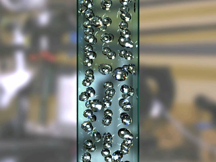
Simulated Bubbly Flow

Photo-Realistic Visualization by the Ray Tracing Method By AVS By Ray Tracing

Simulated Boiling Configuration

Predicted Water-Vapor Configuration Flow direction Outlet Inlet Fuel bundle Predicted result Experimental result

Conclusions Two-phase flow characteristics on liquid film and bubbly flow were predicted by a newly developed analysis code; When a large-scale simulation is carried out under the simulated reactor core geometry, high performance parallelization approach is the most important key technology; The high prospect was acquired on the possibility of establishment of thermal design procedure of nuclear reactors with numerical simulations; and, Furthermore code validation will be continued.

END
- Slides: 21