
A HighlyEfficient RowStructure Stencil Planning Approach for EBeam

A Highly-Efficient Row-Structure Stencil Planning Approach for E-Beam Lithography with Overlapped Characters Jian KUANG, Evangeline F. Y. Young Department of Computer Science and Engineering The Chinese University of Hong Kong 香 港 中 文 大 學 1
Outline Introduction Overall Flow Sub-problems Experimental Results Conclusions 2
Outline Introduction Overall Flow Sub-problems Experimental Results Conclusions 3
Next Generation Lithography To replace optical lithography and multiple patterning lithography Ø mask cost is too high Extreme Ultra-Violet (EUV) Electron-Beam Lithography (E-Beam) Ø both are not ready for mass production yet EUV is delayed by technological difficulties Ø such as mask blank defects E-Beam suffers from low throughput Ø bottleneck 4
E-Beam Lithography (EBL) Maskless lithography technology shoot a beam of electrons onto a wafer and directly creates desired shapes there Ø high resolution Ø relatively lower cost, compared with the cost of masks Ø Writing time ~ number of shots Ø reducing shot number can improve throughput 5

Character Projection Variable Shaped Beam (VSB) Ø Ø every shot can only create one rectangle too slow for high-volume manufacturing Character Projection (CP) Ø Ø Ø various characters will be pre-designed characters can be placed on the stencil a character on the stencil needs only one shot 4 shots are saved 6
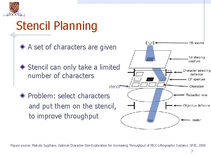
Stencil Planning A set of characters are given Stencil can only take a limited number of characters stencil Problem: select characters and put them on the stencil, to improve throughput Figure source: Makoto Sugihara, Optimal Character-Size Exploration for Increasing Throughput of MCC Lithographic Systems. SPIE, 2009 7
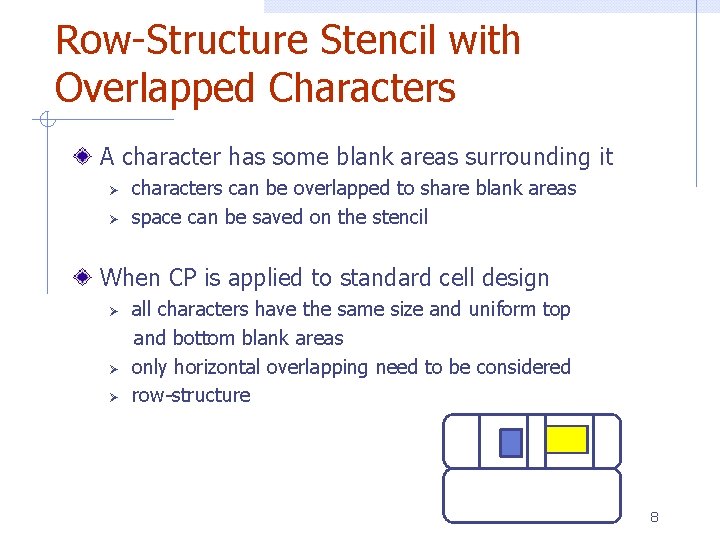
Row-Structure Stencil with Overlapped Characters A character has some blank areas surrounding it Ø Ø characters can be overlapped to share blank areas space can be saved on the stencil When CP is applied to standard cell design all characters have the same size and uniform top and bottom blank areas Ø only horizontal overlapping need to be considered Ø row-structure Ø 8
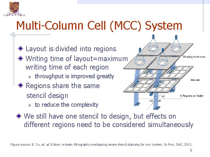
Multi-Column Cell (MCC) System Layout is divided into regions Writing time of layout=maximum writing time of each region Ø throughput is improved greatly Regions share the same stencil design Ø to reduce the complexity We still have one stencil to design, but effects on different regions need to be considered simultaneously Figure source: B. Yu, et. al. E-blow: e-beam lithography overlapping aware stencil planning for mcc system. In Proc. DAC, 2013. 9
Previous Work by Yuan et. al. [1] Ø Ø Ø the first systematic study greedy and heuristic methods slow, no global view Work by Yu et. al. [2] Ø Ø Ø Linear Programming + successive relaxation optimality loss because of rounding failed to differentiate conventional EBL and MCC system Work by Chu et. al. [3] Ø Stencil planning for flexible character design [1] K. Yuan, et. al. E-beam lithography stencil planning and optimization with overlapped characters. TCAD, 31(2): 167– 179, Feb 2012. [2] B. Yu, et. al. E-blow: e-beam lithography overlapping aware stencil planning for mcc system. In Proc. DAC, 2013. [3] C. Chu, et. al. Flexible Packed Stencil Design with Multiple Shaping Apertures for E-Beam Lithography. In Proc. ASPDAC, 2014. 10
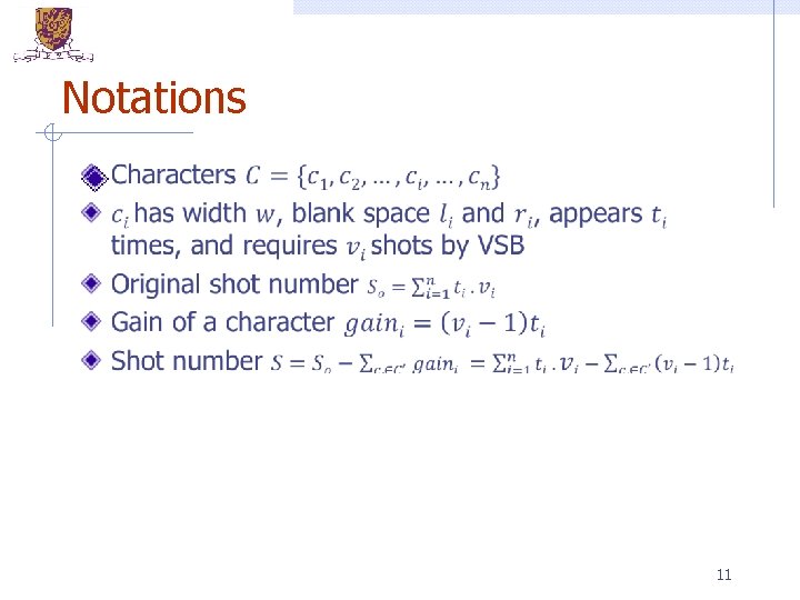
Notations 11
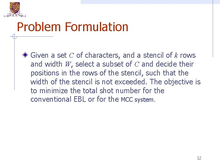
Problem Formulation Given a set C of characters, and a stencil of k rows and width W, select a subset of C and decide their positions in the rows of the stencil, such that the width of the stencil is not exceeded. The objective is to minimize the total shot number for the conventional EBL or for the MCC system. 12
Outline Introduction Overall Flow Sub-problems Experimental Results Conclusions 13
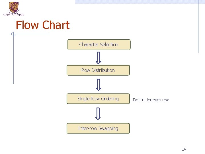
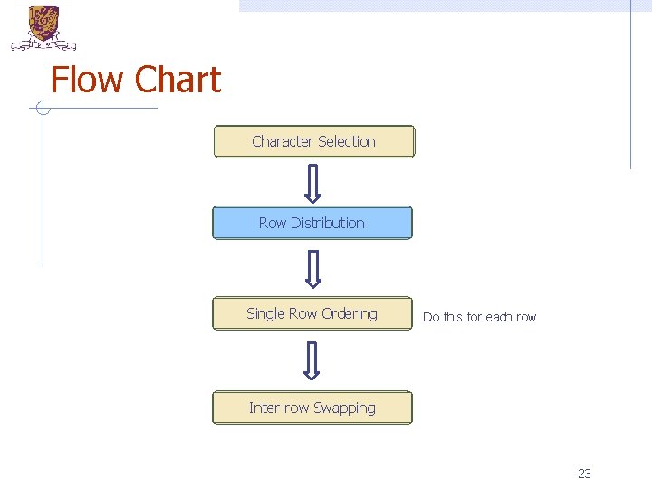
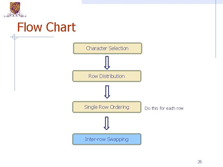
Flow Chart Character Selection Row Distribution Single Row Ordering Do this for each row Inter-row Swapping 14
Outline Introduction Overall Flow Sub-problems Experimental Results Conclusions 15

Flow Chart Character Selection Row Distribution Single Row Ordering Do this for each row Inter-row Swapping 16
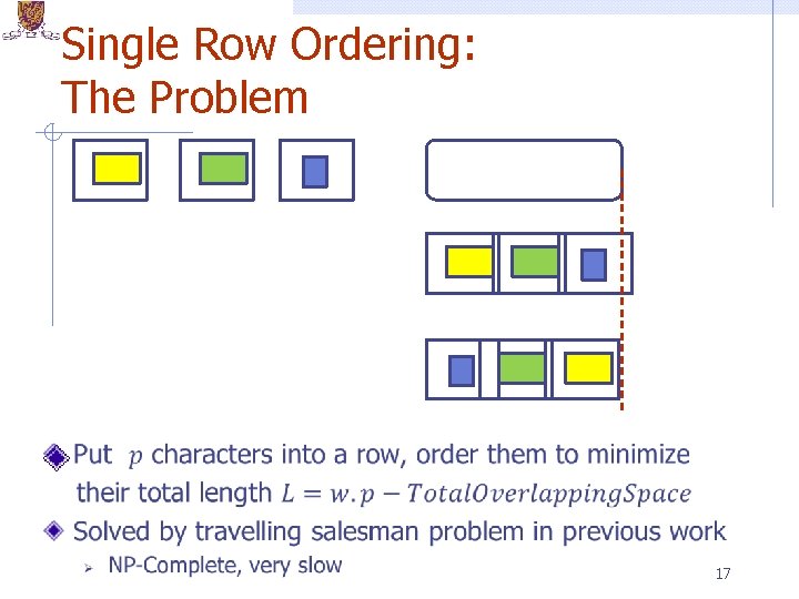
Single Row Ordering: The Problem 17
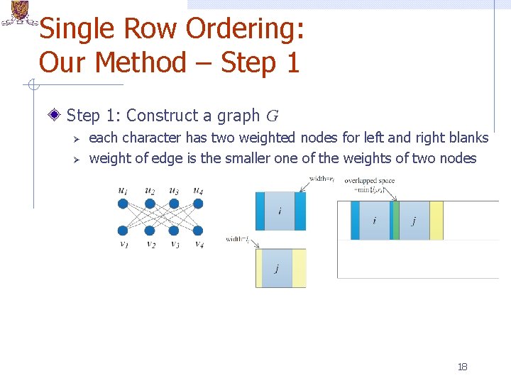
Single Row Ordering: Our Method – Step 1: Construct a graph G Ø Ø each character has two weighted nodes for left and right blanks weight of edge is the smaller one of the weights of two nodes 18
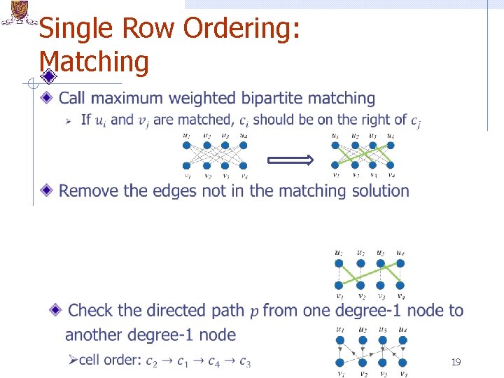
Single Row Ordering: Matching 19
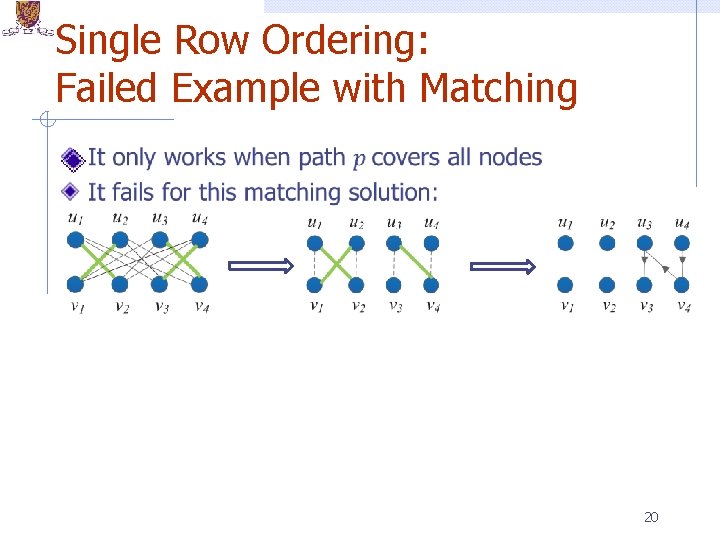
Single Row Ordering: Failed Example with Matching 20
Single Row Ordering: Our Method Step 2: Let weightmin be the minimum weight among all the nodes in G. Update the weight of every node v as weight(v)− weightmin Step 3: Remove those nodes with weight 0 and their corresponding edges. Step 4: Update all the edge weights according the new node weights to obtain graph G'. THEOREM: When all the edges in G' are with equal weight (The Constraint), the maximum weighted matching on G' can always give a character ordering with the 21 optimal overlapping space
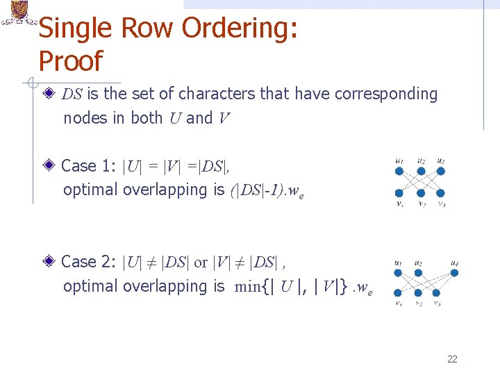
Single Row Ordering: Proof DS is the set of characters that have corresponding nodes in both U and V Case 1: |U| = |V| =|DS|, optimal overlapping is (|DS|-1). we Case 2: |U| ≠ |DS| or |V| ≠ |DS| , optimal overlapping is min{| U |, | V|}. we 22
Flow Chart Character Selection Row Distribution Single Row Ordering Do this for each row Inter-row Swapping 23
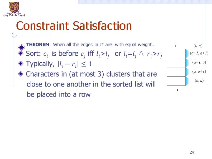
Constraint Satisfaction 24
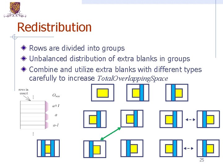
Redistribution Rows are divided into groups Unbalanced distribution of extra blanks in groups Combine and utilize extra blanks with different types carefully to increase Total. Overlapping. Space 25
Flow Chart Character Selection Row Distribution Single Row Ordering Do this for each row Inter-row Swapping 26
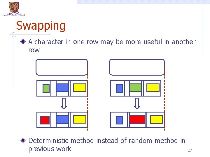
Swapping A character in one row may be more useful in another row Deterministic method instead of random method in previous work 27
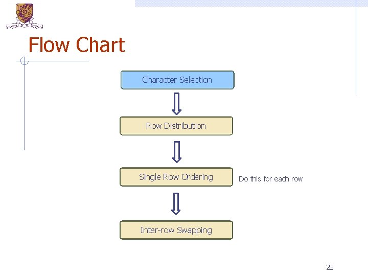
Flow Chart Character Selection Row Distribution Single Row Ordering Do this for each row Inter-row Swapping 28
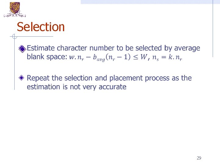
Selection 29
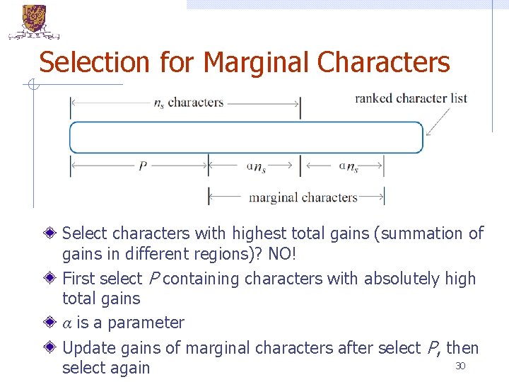
Selection for Marginal Characters Select characters with highest total gains (summation of gains in different regions)? NO! First select P containing characters with absolutely high total gains α is a parameter Update gains of marginal characters after select P, then 30 select again
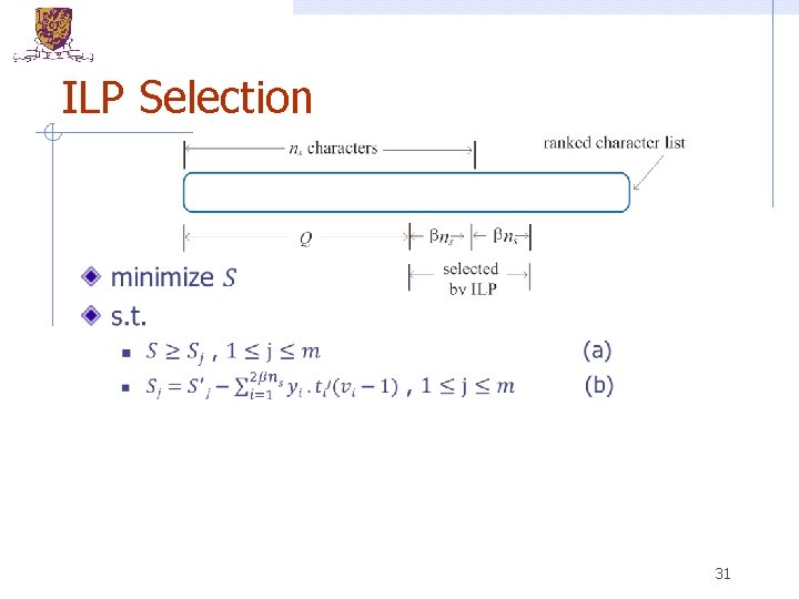
ILP Selection 31
Outline Introduction Overall Flow Sub-problems Experimental Results Conclusions 32
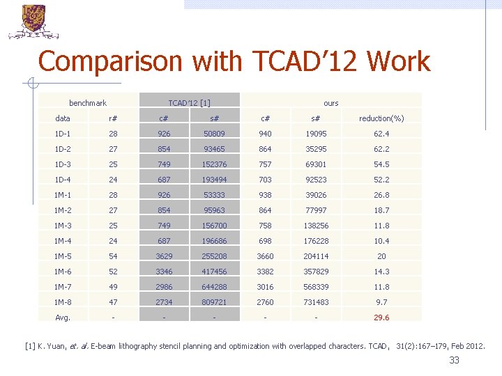
Comparison with TCAD’ 12 Work benchmark TCAD′ 12 [1] ours data r# c# s# reduction(%) 1 D-1 28 926 50809 940 19095 62. 4 1 D-2 27 854 93465 864 35295 62. 2 1 D-3 25 749 152376 757 69301 54. 5 1 D-4 24 687 193494 703 92523 52. 2 1 M-1 28 926 53333 938 39026 26. 8 1 M-2 27 854 95963 864 77997 18. 7 1 M-3 25 749 156700 758 138256 11. 8 1 M-4 24 687 196686 698 176228 10. 4 1 M-5 54 3629 255208 3660 204114 20 1 M-6 52 3346 417456 3382 357829 14. 3 1 M-7 49 2986 644288 3016 568339 11. 8 1 M-8 47 2734 809721 2760 731483 9. 7 Avg. - - - 29. 6 [1] K. Yuan, et. al. E-beam lithography stencil planning and optimization with overlapped characters. TCAD, 31(2): 167– 179, Feb 2012. 33
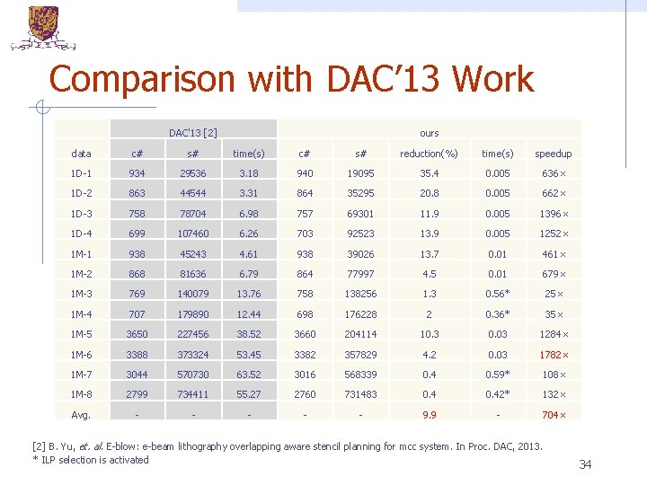
Comparison with DAC’ 13 Work DAC'13 [2] ours data c# s# time(s) c# s# reduction(%) time(s) speedup 1 D-1 934 29536 3. 18 940 19095 35. 4 0. 005 636× 1 D-2 863 44544 3. 31 864 35295 20. 8 0. 005 662× 1 D-3 758 78704 6. 98 757 69301 11. 9 0. 005 1396× 1 D-4 699 107460 6. 26 703 92523 13. 9 0. 005 1252× 1 M-1 938 45243 4. 61 938 39026 13. 7 0. 01 461× 1 M-2 868 81636 6. 79 864 77997 4. 5 0. 01 679× 1 M-3 769 140079 13. 76 758 138256 1. 3 0. 56* 25× 1 M-4 707 179890 12. 44 698 176228 2 0. 36* 35× 1 M-5 3650 227456 38. 52 3660 204114 10. 3 0. 03 1284× 1 M-6 3388 373324 53. 45 3382 357829 4. 2 0. 03 1782× 1 M-7 3044 570730 63. 52 3016 568339 0. 4 0. 59* 108× 1 M-8 2799 734411 55. 27 2760 731483 0. 42* 132× Avg. - - - 9. 9 - 704× [2] B. Yu, et. al. E-blow: e-beam lithography overlapping aware stencil planning for mcc system. In Proc. DAC, 2013. * ILP selection is activated 34
Outline Introduction Overall Flow Sub-problems Experimental Results Conclusions 35
Conclusions The problem is divided into four subproblems that are solved efficiently Both conventional EBL and the MCC system are considered Experiment results demonstrate our efficiency and effectiveness Significant improvement of throughput Remarkable speed-up 36

Thanks! jkuang@cse. cuhk. edu. hk 37
- Slides: 37