A High Performance Scalable FFT for OFDM Dr

A High Performance Scalable FFT for OFDM Dr. J. Greg Nash Centar (www. centar. net) jgregnash@centar. net 2007 IEEE Wireless Communications and Networking Conference Hong Kong, March 11 -15.
 –")
Future 3 G/4 G OFDM Requirements for FFTs • Run-time scalable FFTs (SOFDMA) – 802. 16 e (128, 512, 1024, 2048 points) – 3 GPP LTE (128, 256, 512, 1024, 1536, 2048 points) • Non-power-of-two-transform sizes – 802. 22 WRAN (1024, 2048, 4096, 6144 points) – 3 GPP LTE (128, 256, 512, 1024, 1536, 2048 points) • High performance – Fs = 100 MHz with 4 MIMO streams < 2. 5 sec for 1 K FFT) • Run-time partial FFT computations (OFDMA) • High dynamic range (~90 db) • Simple, regular, locally connected, maintainable circuit

Comparisons with Traditional Pipelined FFTs
 • OFDMA downlink parameters including all")
FFT Estimates for 3 GPP LTE (Wi. Max) • OFDMA downlink parameters including all FFT sizes (more stringent than Wi. Max) • “Streaming” FFT architecture with non- sequential transform outputs • Worst case power (continuous 2048 point FFT calculations)

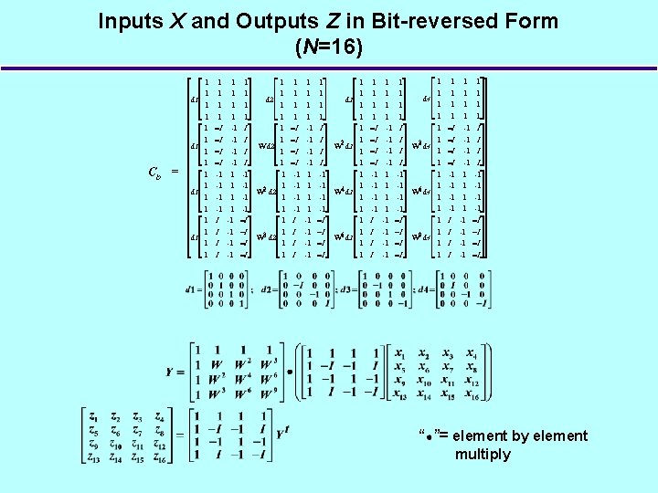
New Base-4 DFT Matrix Equation • Traditional DFT matrix form: • New matrix form for DFT† “ ”= element by element multiply • CM 1 and CM 2 contain only elements from the set – CM 1 X and CM 2 Yt only involve complex additions/subtractions • Twiddle factor matrix WM is of size N/4 x N/4 rather than N x N of C – x 16 fewer multiplies than traditional DFT equation (Z=CX) †J. . G. Nash, “Computationally efficient systolic architecture for computing the discrete Fourier transform, ” IEEE Transactions on Signal Processing, Volume 53, Issue 12, Dec. 2005, pp. 4640 – 4651

Base-4 FFT Architecture Base-4 DFT equations: Base-4 DFT architecture:
 1024 Point FFT (M=32) Array Processing Elements")
Base-4 Array Architecture 256 Point FFT (M=16) 1024 Point FFT (M=32) Array Processing Elements

Processing flow for DFT of length N = Nr Nc 1 Nc column DFTs (Xci) of length Nr – Array length is Nr /4 – N/4 clock cycles 2 Twiddle multiplication – Only multipliers used – 4 Nc clock cyles – Without this step a 2 -D FFT is done 3 Nr row DFTs (Xri) of length Nc – (Nc)2/4 clock cylces
 • Based on “streaming” FFT (continuous data in")
Circuit Comparisons with Pipelined FFT (1) • Based on “streaming” FFT (continuous data in and out) • Benchmark against Altera FFT (Block Floating Point) – Base-4 16 -bit circuit – Altera circuit with comparable signal to (roundoff) noise ratio – Circuits mapped to same Altera Stratix II FPGA • Same VHDL compiler used (Quartus II)
 regions – 85")
High Dynamic Range • Architecture supports multiple block floating point (BFP) regions – 85 -90 db S/QN with 16 -bit word lengths – Wordlength reduced by more than 4 -bits compared to other BFP implementations with equivalent signal-to-quantization-noise (S/QN) • Comparisons of “single tone” data sets (“streaming” FFT):
 • Based on Altera pipelined FFT (Stratix II")
Circuit Comparions with Pipelined FFT (2) • Based on Altera pipelined FFT (Stratix II FPGA 90 nm technology) • Figure of Merit (FOM) = Area (ALMs) x Throughput (Cycles/DFT) x Mem (Kbits)/Clock(Hz) • “Streaming” circuits: Altera (20 -bit) and base-4 (16 -bit)

Run-Time Partial FFT Calculation • OFDMA – Receivers may only use a small fraction of the transmitted data – Transmitters may each simultaneously send a smaller number of separate signals • Base-4 matrix equation – Structure provides for partitioning the FFT computation into simpler sub-calculations – Computation savings • Only compute desired row transform inputs • Only compute desired elements in row transforms – Memory savings • Potentially fewer outputs, inputs and intermediate results • Performance improvement depends strongly on sub-carrier allocations
 • Cycle input twice • Option 1 – All column DFTs –")
Scaling (2) • Cycle input twice • Option 1 – All column DFTs – All twiddles – All row DFTs • Option 2 – Normal ordering 1 (half Z values) 2 (other half) N = 1024 Nr=Nc=32
 : • Multiplications = M")
Discreet Fourier Transform • Mathematical form: • C (M=16) : • Multiplications = M 2

Possible Transform Sizes • Base-4 – Matrix derivation requires M = 16, 32, 48, . . . – N = Nr Nc = (16 p) (16 q) = 256 n • Base-2: – Matrix derviation assumes M = 4, 8, 12, . . . – N = Nr Nc = (4 p) (4 q) = 16 n • Base-2 (No row/column factorization) – N = M = 4 n (n, p, q = 1, 2, 3, . . )
 • • Trade-off between throughput and resouces used FOM = Area")
Scaling Option (1) • • Trade-off between throughput and resouces used FOM = Area (ALMs) x Throughput (Cycles/DFT)/ Clock (MHz)/1000 Nominal clock = 350 MHz Estimates
 • Use same circuit to do different transform sizes (e. g. ,")
Scaling (2) • Use same circuit to do different transform sizes (e. g. , run-time) • Base-4 matrix equation: • Process each CB multiplication separately using blocks of 4 rows • Example: 1024 -point transform (Nr=Nc=32)
- Slides: 18