A Guide to 23 CFR 625 Requirements for


")
")


 by minimum of 4%")
 PE 8. 0 x 10 -5")


 Slide 52")
 Slide 53")
 Slide 54")
 Downstream Manholes Slide 55")

- Slides: 56
A Guide to 23 CFR 625 Requirements for Culverts & Pipe AASHTO LRFD Section 12 Standards
A User’s Guide: 3
4 A User’s Guide • Background: In 2013, following the passage of MAP-21 which contained language granting the states autonomy on the selection of culvert pipe material type, the FHWA issued language addressing the culvert design issue in their Final Rule which was published in the Federal Register on January 28, 2013. In that rule they wrote: “Although section 1525 gives the States the autonomy to determine culvert and storm sewer material types, section 1525 does not relieve the States of compliance with other applicable Federal requirements, such as Buy America, culvert design standards in 23 CFR part 625…”
5 A User’s Guide • 23 CFR 625: Currently, section 23 CFR 625 of the Federal Regulations refers to: “AASHTO LRFD Bridge Design Specifications, 7 th Edition, AASHTO, 2014, with 2015 Interim Revisions” for use in designing buried structures, including culverts. • FHWA July 2016 Email: On July 20, 2016, the FHWA sent an email to all of their district offices reiterating the design requirement.
FHWA Email – July 20, 2016 6
A User’s Guide: AASHTO LRFD Bridge Design Specifications 7 • Section 12 of these specifications covers the designs of concrete pipe, metal pipe and plastic pipe. • Concrete Pipe Designs in Section 12 can be performed using either Indirect or Direct design. § Indirect designs for the pipe can be found in the latest edition of ASTM Specification C-76 “Standard Specification for Reinforced Concrete Culvert, Storm Drain, and Sewer Pipe” and can be used in conjunction with ASTM Specification C-1479 “Standard Practice for Installation of Precast Concrete Sewer, Storm Drain, and Culvert Pipe Using Standard Installations”.
A User’s Guide: AASHTO LRFD Bridge Design Specifications 8 • Plastic and Metal Pipe designs, because they are highly dependent on the soil/pipe envelope for structural strength and support, must be direct designs as soil types and properties are different at virtually all installation locations. • Additionally, plastic pipe designs rely heavily on the pipe wall profile which is different for every pipe manufacturer. • Consequently, the use of typical fill height tables as a substitute for pipe/soil structural design is not valid.
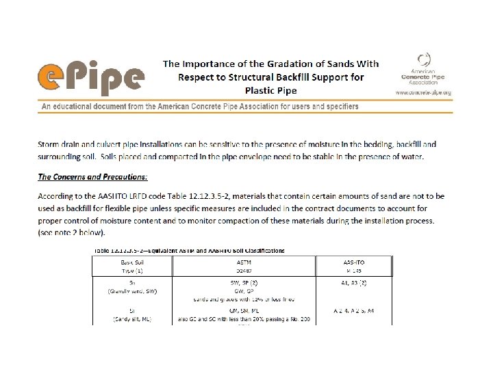
A User’s Guide: Design Notes e. Pipe Design Notes: A series of e. Pipe Design notes have been developed to assist the engineer in some inconclusive areas of the plastic pipe design standard. The standard is silent on the use of trench boxes for construction. As such, without proper research into trench design arching factors, a question arises as to the accuracy of designs using trenches. Additionally, the use of sand backfills, and water table levels and resulting hydrostatic forces on plastic pipe need to be addressed by the designer beyond the guidelines in the specification. e. Pipe Design Notes: • Flexible and Rigid Pipe Installation Review and Discussion • Trust, but Verify • The Importance of the Gradation of Sands With Respect to Structural Backfill Support for Plastic Pipe • Water Table Concerns for Storm Drain and Culverts • Plastic Fill Height Table Pitfalls • Plastic Pipe Profile Predicament Resource # e-022 Resource # e-023 Resource # e-024 Resource # e-025 Resource # e-027 Resource # e-028 9
12 AASHTO Section 12
AASHTO LRFD 13
AASHTO LRFD 14
AASHTO LRFD 15
16 Step 1 - Deflection
17
Plastic Pipe Wall Profiles 18
e. Pipe – The Plastic Pipe Profile Predicament 19 Critical Design Input: • Pipe wall geometry plays an important role in the structural performance of a plastic pipeline. If the engineer allows plastic pipe in the specifications, consideration must be given to the fact that each pipe wall profile is different and requires a unique effective area (Aeff ) for each size of pipe from each individual pipe manufacturer and manufacturing facility. • This data is required (AASHTO LRFD code 12. 3. 10. 1 Resistance to Axial Thrust) and must be accurate in the structural calculations – generic fill height tables will not address all available profile offerings.
Loads on Plastic Pipe 20
21 Loads on Plastic pipe and
Vertical Arching Factor VAF for embankments is usually 0. 4 to 0. 6 22
e. Pipe – Flexible and Rigid Pipe Installation Review and Discussion Critical Design Input: 23 • Depending on the backfill materials used in a trench installation, as well as the width of the trench, lateral support for the pipe, and the relative column strength of the side-fill, soils may not develop to the same extent as assumed when a flexible pipe is installed in an embankment. The vertical load on the side-fill soils is reduced, which then reduces the stiffness of the soil columns as well as the lateral resistance that can be developed in the side-fill soils. • In this condition, the Vertical Arching Factor (VAF) may likely be higher than assumed by equation 12. 3. 5 -3 to the point that it may be more than 1. 0. this means that the flexible pipe may actually see an increase to the soil prism load directly above the pipe compared to the assumed embankment condition, which is not accounted for in current designs.
24 e. Pipe – Flexible and Rigid Pipe Installation Review and Discussion • Until appropriate research is completed to verify the use of embankment VAF as the conservative assumption for all Flexible pipe installations, it is recommended that trench installations not be allowed or at a minimum not receive the benefit from a VAF less than 1. 0 in LRFD calculations. Minimum trench widths should be established to ensure that the installed pipe system meets the assumptions of an embankment.
25 ADS Technical Note – Trench Boxes
26 Constrained Soil Modulus (Ms )
27 Constrained Soil Modulus (Ms )
28 Soil Type Table
29 e. Pipe – The Importance of Gradation of Sands With Respect to Structural Backfill Support for Flexible Pipe • As the AASHTO Section 12 Plastic Pipe Design procedure warns, uniformly graded material with an average particle size smaller than a No. 40 sieve “should not be used as backfill for thermoplastic culverts. ” • If, however, the design engineer allows the use of such material, that decision requires extra precautions during design and installation. • The design engineer must take into consideration the actual moisture content and compaction levels of the chosen backfill material and additionally monitor and measure these factors during construction.
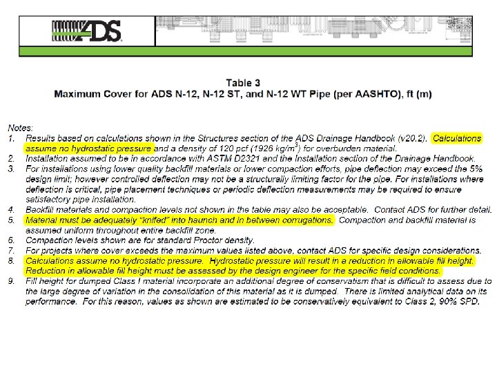
30 Hydrostatic Pressure
Hydrostatic Pressure 31
I-75 Sarasota, FL 2016 32
Common St. - Lake Charles, LA 33
34 Installed and backfilled plastic pipe following rainfall of July 25, 2011:
Lafayette, LA - 2/26/16 35
36 Manufacturer’s Cautions
ADS Technical Note - Flotation 37
38 e. Pipe – Water Table Concerns for Storm Drains and Culverts • The soil-pipe interaction analysis needs to account for the buoyant effect on the pipe and impact on the critical passive soil pressure that a water table has on the soils used in the installation of plastic pipe. • Fluctuations in the water table have a limited effect on rigid concrete pipe since the active lateral earth pressure pushing on the sides of the pipe actually increases when the internal friction in the soil is reduced, and buoyant forces are negligible compared to concrete pipe weight. • Because of this, engineers have become accustomed to using fill height tables without regard to the elevation of the water table.
39 e. Pipe – Water Table Concerns for Storm Drains and Culverts • The buoyant force on a flexible pipe can add between 5% and 20% to the vertical load assumed in the design, thereby increasing the Vertical Arching Factor that is calculated per the current AASHTO LRFD code. • (Note: The loss of side soil support due to migration caused by water table fluctuations can be critical to the structural capacity of flexible pipe and must be considered by the design engineer. ) • Designers default to using manufacturer tables without taking into consideration all of the design caveats.
40 e. Pipe – Plastic Fill Height Table Pitfalls Water Table Impact: • According to AASHTO LRFD Code 12. 3. 7 – Soil Prism, there are three different equations to utilize in design based on the elevation of the top of pipe relative to the elevation of the water table. • Not knowing this exact project variable for each section of a line, the design engineer cannot use the provided manufacturer fill height tables if water tables are present since this variable is not addressed in the tables.
Soil Prism Load 41
42 ADS Technical Note – Fill Height Tables
44 Florida DOT – Fill Height Tables
45 Florida DOT – Fill Height Tables
46 e. Pipe – Plastic Fill Height Table Pitfalls Trench Installations: • A second design omission within the AASHTO LRFD Section 12 code deals with a lack of trench installation investigation. The impact of this lack of investigation is compounded when a trench box is utilized for a particular installation. • A critical component of the structural capacity of the soilplastic pipe system is dependent on the design of the backfill envelope where the side supporting fill must be strong enough to support the horizontal deflection. • When a trench box is utilized and placed within the pipe zone, this all important side fill is dramatically disturbed when the box is moved to the next section. • This action creates voids in this critical haunch and side embedment zone thereby reducing any vertical arching benefit, reducing the soil column strength on each side of the pipe, and subjecting the pipe to strains beyond those allowed by design.
Hydraulic Considerations
48 Hydraulics Reduces Q (flow) by minimum of 4%
49 Coefficients of Thermal Expansion Coefficient (in/in/0 F) PE 8. 0 x 10 -5 PP 4. 2 x 10 -5 PVC 3. 0 x 10 -5 Alum. 1. 3 x 10 -5 Steel 6. 5 x 10 -6 Concrete 5. 5 x 10 -6 Change (in/100 ft/100 F) 0. 96” 0. 52” 0. 36” 0. 16” 0. 08” 0. 07”
50 Thermal Effects • Length change in HDPE § § 1400 F in sun at side of trench pipe installed & backfilled ground temperature 600 F 800 F change = 1. 5” change in length per 20’ section (0. 00008 x 20 x 12 x 80)
Frequency of Crashes Involving Flammable Liquids 51
52 Houston, TX Tanker Fire (I-10 and Hwy. 59) Slide 52
53 Houston, TX Tanker Fire (I-10 and Hwy. 59) Slide 53
54 Houston, TX Tanker Fire (I-10 and Hwy. 59) Slide 54
55 Houston, TX Tanker Fire (I-10 and Hwy. 59) Downstream Manholes Slide 55
56 Liability & Risk • Concrete Pipe: Little or None • Plastic Pipe: § § § No structural design Trench Boxes Flotation Thermal Effects Reduced Hydraulics Fires